Sign In
Upload
Manuals
Brands
SICK Manuals
Scanner
LS-MS3-CO-IO-5M
SICK LS-MS3-CO-IO-5M Manuals
Manuals and User Guides for SICK LS-MS3-CO-IO-5M. We have
1
SICK LS-MS3-CO-IO-5M manual available for free PDF download: Operating Instructions Manual
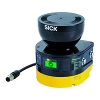
SICK LS-MS3-CO-IO-5M Operating Instructions Manual (168 pages)
Safety laser scanner
Brand:
SICK
| Category:
Scanner
| Size: 18 MB
Table of Contents
Table of Contents
3
1 Ordering Information
7
Microscan3 Core I/O Ordering Information
7
2 About this Document
8
Function of this Document
8
Scope
8
Target Groups of These Operating Instructions
8
Further Information
8
Target Groups and Selected Chapters of These Operating Instructions
8
Symbols and Document Conventions
9
3 Safety Information
10
General Safety Notes
10
Laser Class 1M
10
Intended Use
11
Inappropriate Use
11
Requirements for Personnel Qualifications
11
4 Product Description
13
Setup and Function
13
Principle of Time-Of-Flight Measurement
13
Light Pulses Scan an Area
14
Product Characteristics
15
Device Overview
15
Variants
16
Status Indicators
16
Status Leds
16
Connections
17
System Plug
17
Field Types
18
Field Types and Their Function
18
Protective Field, Shown in Red in this Document
19
Reference Contour Field, Shown in Blue-Green in this Document
19
Field Set
20
Warning Field, Shown in Yellow or Orange in this Document
20
Monitoring Case
21
Field Set, Consisting of One Protective Field (Red) and 2 Warning Fields (Orange and Yellow)
21
Monitoring Case 1 with Field Set 1
21
Example Applications
22
Monitoring Case 2 with Field Set 2
22
Hazardous Area Protection: Detection of the Presence of a Person in the Haz- Ardous Area
22
Hazardous Point Protection: Hand Detection
23
Access Protection: Detection of a Person When Accessing a Hazardous Area
23
Mobile Hazardous Area Protection: Detection of a Person When a Vehicle Approaches
24
5 Project Planning
25
Manufacturer of the Machine
25
Operator of the Machine
25
Assembly
26
Prevent Crawling Beneath
26
Protection from Influences
27
Prevent Stepping over
27
Preventing Unprotected Areas
28
Unsecured Areas
28
Mounting with Deflector Plates (Example)
29
Mounting in an Undercut (Example)
29
Response Time of the Safety Laser Scanner
30
Reference Contour Monitoring
30
Mounting in Vehicle Paneling (Example)
30
Monitoring Case Switching Time
32
Tolerance Band of the Reference Contour Field
32
Opening, Edge of the Protected Opening = Reference Contour)
32
Overrun of the Protective Field in Front of an Opening
32
Hazardous Area Protection
34
Stationary Application with Horizontal Scan Plane for Hazardous Area Protection.34
34
Protection against Reaching over When Mounted Low (Dimensions in MM)
37
Protection against Reaching over When Mounted High (Dimensions in MM)
37
Scan Plane at Ankle Height
38
Scan Plane at Calf Height
39
Distance of the Protective Field from the Wall
40
Hazardous Point Protection
41
Stationary Application in Vertical Operation for Hazardous Point Protection
41
Access Protection
43
Stationary Application in Vertical Operation for Access Protection
44
Mobile Hazardous Area Protection
46
Mobile Application in Horizontal Operation for Hazardous Area Protection
46
Flat-Rate Supplement ZF for Lack of Ground Clearance
47
Minimum Supplement for Lack of Ground Clearance
48
Stopping Distance as a Function of the Vehicle's Speed
49
Integrating the Equipment into the Electrical Control
51
Recommended Fitting Height
51
Recommended Fitting Height for Inverted Mounting
51
Voltage Supply
53
USB Connection
53
Ossds
53
Dual-Channel and Isolated Connection of OSSD1 and OSSD2
54
No Potential Difference between Load and Protective Device
54
Control Inputs
55
Universal Inputs, Universal Outputs, Universal I/Os
56
Restart Interlock
56
Status of the Channels of the Control Inputs with Complementary Evaluation
56
How the Restart Interlock Works (1): no One in Protective Field, Machine Operates
57
How the Restart Interlock Works (2): Person Detected in Protective Field, Safety Out- Put in off State
58
How the Restart Interlock Works (3): Person in Hazardous Area, no Detection in Pro- Tective Field, Safety Output Still in off State
58
External Device Monitoring (EDM)
59
Connection Diagrams
59
Restarting the Machine
59
Testing Plan
60
Test During Commissioning and in Certain Situations
60
Connection Diagram with Restart Interlock and External Device Monitoring (EDM)60
60
Regular Inspection
61
Notes on the Tests
62
6 Mounting
65
Safety
65
Unpacking
65
Mounting Procedure
66
Prevent Crawling Beneath
66
Prevent Stepping over
66
Fitting the System Plug
67
Installing the System Plug on the Safety Laser Scanner
67
Direct Mounting
68
Mounting the Safety Laser Scanner Directly
68
7 Electrical Installation
69
Safety
69
Connection Overview
70
Connecting OSSD1 and OSSD2
70
No Potential Difference between Load and Protective Device
70
Microscan3 Core
71
Pin Assignment
71
Connecting Cable with M12 Plug Connector
71
System Plug and Connections: Microscan3 Core
71
Pin Assignment of the Connecting Cable with M12 Plug Connector
71
8 Configuration
72
General Requirements
72
Delivery State
72
Safety Designer
72
Installation Assistant
72
Projects
72
User Interface
73
User Groups
73
Pin Assignment of the Connecting Cable (Male Connector, M12, 8-Pin, A-Coded). 71 52. Software Controls
73
Settings
74
User Groups
74
Configuration
77
Configuration
78
Overview
79
Functional Scope
80
Reading Configuration
81
Functional Scope
81
Identification
82
Application
84
Monitoring Plane
85
Parameters for the Monitoring Plane
85
Parameters for the Safety Laser Scanner
87
Recommended Multiple Sampling
87
Reference Contour Field
89
Fields
90
Using the Field Editor
91
Field Editor
91
Buttons on the Toolbar
91
Colors of the Field Types
92
Buttons for Field Sets
93
Creating Field Set Templates
94
Importing and Exporting Field Sets and Fields
95
Background Image
95
Field Set Template
95
Settings for the Field Editor
96
Background Image
96
Editing Fields Using Coordinates
97
Drawing in Points that Cannot be Monitored
98
Editing Fields Using Coordinates
98
Area that Cannot be Monitored
99
Enable Propose Field
100
Inputs and Outputs, Local
102
Input Signals
103
Output Signals
103
Further Settings for some Signals
104
Monitoring Cases
105
Settings for Monitoring Case Tables
106
Settings for Monitoring Cases
106
Empirical Values for the Required Input Delay
106
Input Conditions
107
Cut-Off Paths
107
Assigning Field Sets
107
Simulation
108
Transfer
109
Starting and Stopping Safety Function
110
Reports
110
Report
110
Service
111
Device Restart
111
Factory Settings
112
Managing Passwords
112
Optics Cover Calibration
113
9 Commissioning
114
Safety
114
Alignment
114
Switching on
115
Alignment about the Transverse Axis
115
Alignment about the Depth Axis
115
Check During Commissioning and Modifications
116
Status Leds
116
10 Operation
117
Safety
117
Regular Thorough Check
117
Leds
117
Status Leds
117
Buttons and Display
118
Pushbuttons on the Device
118
Status Leds
118
Overview of Status Information
119
Menu
121
11 Maintenance
122
Safety
122
Regular Cleaning
122
Replacing the Optics Cover
123
Fixing Screws for the Optics Cover
124
Replacing the Safety Laser Scanner
125
Replacing the Safety Laser Scanner Without System Plug
126
Completely Replacing the Safety Laser Scanner
126
Replacing the System Plug
127
Installing the System Plug on the Safety Laser Scanner
127
Regular Thorough Check
128
12 Troubleshooting
129
Safety
129
Diagnostic Leds
129
Status Leds
129
Diagnostics Using the Display
130
Status Display
130
Status Leds
130
Overview of Status Information
130
Detailed Diagnostics
132
Pushbuttons on the Device
133
Menu
133
Fault Display
134
Fault Types
134
Diagnostics Using Safety Designer
136
Data Recorder
137
Event History
138
Message History
140
Print Message History or Save as a PDF
140
13 Decommissioning
141
Disposal
141
14 Technical Data
142
Variant Overview
142
Version Numbers and Functional Scope
142
Data Sheet
142
Microscan3 Core I/O
142
Devices and Type Codes
142
Functional Scope of LS-MS3-CO-IO-5M
142
Functional Scope
142
Features
142
Safety-Related Parameters
143
Interfaces
144
Electrical Data
144
Mechanical Data
146
Ambient Data
146
Response Times
147
Miscellaneous Data
147
Response Time of an Individual Safety Laser Scanner
148
Course of the OSSD Test over Time
149
Sensing Range
149
Switch-Off Tests
149
Duration and Time Offset for the Switch-Off Tests in an OSSD Pair
149
Protective Field Range (Devices with a Max. Protective Field Range of 5.5 M)
149
Scanning Range and Object Size for Warning Fields
150
Scanning Range and Required Remission for Warning Fields
151
Dimensional Drawings
152
Dimensional Drawing
152
15 Glossary
153
16 Annex
157
Compliance with EU Directives
157
Note on Specified Standards
158
Checklist for Initial Commissioning and Commissioning
159
Mounting Methods for Protection from Interference from Systems in Close Proximity
160
Mounting 2 Safety Laser Scanners with the Optics Cover Facing Upward
160
Mounting 2 Safety Laser Scanners with the Optics Cover Facing Downward
160
Mounting the Upper Safety Laser Scanner with the Optics Cover Facing Downward and Mounting the Lower Safety Laser Scanner with the Optics Cover Facing Upward
161
Mounting 2 Safety Laser Scanners Opposite One Another
162
Mounting 2 Safety Laser Scanners Next to One Another
162
List of Figures
163
18 List of Tables
165
Advertisement
Advertisement
Related Products
SICK LD-MRS400001
SICK LD-MRS400102
SICK LD-MRS420201
SICK LD-MRS800001
SICK LSI 101
SICK LMC121
SICK LD-MRS HD
SICK LBR
SICK LMS5 1 Series
SICK LBC65 Series
SICK Categories
Accessories
Security Sensors
Measuring Instruments
Scanner
Barcode Reader
More SICK Manuals
Login
Sign In
OR
Sign in with Facebook
Sign in with Google
Upload manual
Upload from disk
Upload from URL