Sign In
Upload
Manuals
Brands
SICK Manuals
Security Sensors
LD-OEM15 Series
SICK LD-OEM15 Series Measurement Sensor Manuals
Manuals and User Guides for SICK LD-OEM15 Series Measurement Sensor. We have
1
SICK LD-OEM15 Series Measurement Sensor manual available for free PDF download: Operating Instructions Manual
SICK LD-OEM15 Series Operating Instructions Manual (72 pages)
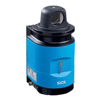
Laser measurement sensor
Brand:
SICK
| Category:
Security Sensors
| Size: 3 MB
Table of Contents
Table of Contents
3
About this Document
9
Function of this Document
9
Target Group
9
Depth of Information
9
Tab. 1: Target Groups of this Document
9
Symbology Used
10
For Your Safety
11
Authorised Personnel
11
Tab. 2: Authorised Personnel
11
Intended Use
12
General Safety Notes and Protective Measures
13
Fig. 1: Laser Output Aperture on the LD-OEM
14
Quick Stop and Quick Restart
15
Environmental Protection
15
Product Description
16
Scope of Delivery
16
Tab. 3: Scope of Delivery
16
Construction of the LD-OEM
17
Fig. 2: Views of Device
17
Tab. 4: Meaning of the LED Status Indicators
19
Fig. 3: LED Displays
19
Special Features of the LD-OEM
20
Tab. 5: Special Features of the LD-OEM
20
Applications
21
Operating Principle of the LD-OEM
21
Fig. 4: Example of the Measurement Result
21
Fig. 5: Diffuse Reflection from Objects
22
Tab. 6: Typical Remissions and Scanning Ranges
23
Fig. 6: Directional Reflection from Reflectors
23
Fig. 7: Possible Sources of Errors During the Measurement
23
Fig. 8: Beam Diameter and Distance between Measured Points at 0 to 100 M
24
Output of Measured Values
25
Field Application (LD-OEM1500)
25
Fig. 9: Principle of Field Application
25
Tab. 7: Buttons for Managing the Evaluation Cases
26
Tab. 8: Buttons for Managing the Evaluation Fields
29
Fig. 10: Selection of the Method for Creating Evaluation Fields
30
Tab. 9: Buttons for Changing the Field Editor View
31
Fig. 11: End Points for a Field
32
Fig. 12: Setting End Points 1
32
Fig. 13: Setting End Points 2
33
Fig. 14: Moving End Points 1
33
Fig. 15: Moving End Points 2
33
Fig. 16: Deleting End Points 1
34
Fig. 17: Deleting End Points 2
34
Fig. 18: Moving a Rectangular Field
35
Fig. 19: Increasing or Reducing the Size of a Rectangular Field
35
Fig. 20: Rotating a Rectangular Field
36
Fig. 21: Starting Points for a Field
37
Fig. 22: Intrusion Display None (no Objects)
39
Fig. 23: Intrusion Display Normal (with Objects)
39
Fig. 24: Intrusion Display Freeze (Clear Field, but the Object Remains. Frozen until New Field Intrusion.)
40
Fig. 25: Intrusion Display Single (Frozen until "Reset Intrusion" Is Activated)
40
Fig. 26: Intrusion Display: Tracking
40
Integration of the LD-OEM in Other Control Systems
41
Fig. 27: Requesting Contour Data
42
Fig. 28: Pulse for Synchronisation
42
Fig. 29: Pulse on the Head Position
43
Planning
44
Tab. 10: Beam Diameter at Different Distances from the LD-OEM
45
Fig. 30: Increase in the Size of the Beam and Safety Supplement
45
Assembly
46
Overview of the Mounting Steps
46
Preparations for Mounting
46
Mounting and Adjustment of the Device
47
Dismantling the LD-OEM
47
Electric Installation
48
Overview of the Installation Steps
48
Connections of the LD-OEM
48
Fig. 31: Connections of the LD-OEM
48
Preparing the Electrical Installation
49
Tab. 11: Pin Assignment of the "Power" Connection on the LD-OEM
49
Tab. 12: Pin Assignment of the "Ethernet" Connection on the LD-OEM
49
Tab. 13: Pin Assignment of the "RS232" Connection on the LD-OEM
49
Undertaking Electrical Installation on the LD-OEM
50
Tab. 14: Maximum Cable Lengths for the Supply Voltage
50
Tab. 15: Maximum Length of Cable for the Data Interface
50
Fig. 32: Connection of the Voltage Supply
51
Fig. 33: Ethernet Connection
51
Fig. 34: Wiring the RS232 Interface
51
Fig. 35: RS232 Connection (LD-OEM1500)
52
Fig. 36: RS232 Connection (LD-OEM1501)
52
Commissioning and Configuration
53
Overview of the Commissioning Steps
53
SOPAS et Configuration Software
53
Establish Communication with the LD-OEM
54
Tab. 16: SOPAS et Default Setting
54
Fig. 37: IP Communication with Fixed IP Address
56
Fig. 38: Configuring with Autoip
57
Initial Start-Up
58
Tab. 17: Password LD-OEM
58
Fig. 39: Principle of Data Storage
58
Connection and Test Measurement
60
Service
61
Maintenance During Operation
61
Fig. 40: Window in the Scanner Head on the LD-OEM
61
Exchanging a LD-OEM
62
Troubleshooting
63
In the Event of Fault
63
Monitoring Error and Malfunction Indications
63
Troubleshooting and Rectification
64
Detailed Error Analysis
64
Tab. 18: Troubleshooting and Rectification
64
SICK Support
65
Technical Data
66
Data Sheet LD-OEM
66
Tab. 19: Data Sheet LD-OEM
66
Dimensional Drawings
68
Advertisement
Advertisement
Related Products
SICK LD-MRS
SICK LFV 230
SICK LD-MRS400001
SICK LD-MRS400102
SICK LD-MRS420201
SICK LD-MRS800001
SICK LD-MRS HD
SICK LD-LRS
SICK LMC131
SICK LBC632
SICK Categories
Accessories
Security Sensors
Measuring Instruments
Scanner
Barcode Reader
More SICK Manuals
Login
Sign In
OR
Sign in with Facebook
Sign in with Google
Upload manual
Upload from disk
Upload from URL