Sign In
Upload
Manuals
Brands
SICK Manuals
Barcode Reader
CLV640
SICK CLV640 Barcode Scanners Manuals
Manuals and User Guides for SICK CLV640 Barcode Scanners. We have
3
SICK CLV640 Barcode Scanners manuals available for free PDF download: Operating Instructions Manual, Technical Information
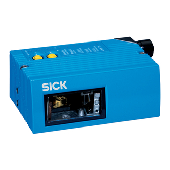
SICK CLV640 Operating Instructions Manual (132 pages)
Brand:
SICK
| Category:
Barcode Reader
| Size: 7 MB
Table of Contents
Software Versions
2
Table of Contents
3
Abbreviations
5
Figures and Tables
5
Tables
6
Figures
7
1 Notes on this Document
11
Purpose
11
Target Group
11
Depth of Information
11
Tab. 1-1: Target Group
11
Used Symbols
12
2 Safety Information
13
Authorised Users
13
Tab. 2-1: Required Qualification for Starting up the Bar Code Scanner
13
Intended Use
14
General Safety Precautions and Protection Measures
14
Fig. 2-1: Outlet Opening of the Laser Radiation at the Reading Window (Shown Here: Ethernet Version)
15
Tab. 2-2: Laser Data of CLV640
16
Fig. 2-2: Laser Warning Sign Attached to the Bar Code Scanner at Delivery
16
Quick Stop and Quick Restart
17
Environmental Information
18
3 Quick-Start
19
Preparing the Bar Code Scanner for the Quick Start
19
Establishing Connection with the Bar Code Scanner
19
Performing the Reading
20
Fig. 3-1: Register Tab Quickstart
20
4 Product Description
23
Setting up the Bar Code Scanner
23
Fig. 4-1: Housing Types of the CLV640 Bar Code Scanner
24
Fig. 4-2: Device View of the CLV640 Bar Code Scanner (Shown Here: Ethernet-Version)
25
Included in Delivery
26
Tab. 4-1: CLV640 Bar Code Scanner Delivery
26
Device Versions
27
System Requirements
27
Tab. 4-2: Variants of the CLV640 Bar Code Scanner
27
Product Features and Functions (Overview)
28
Bar Code Scanner Methods of Operation
29
Tab. 4-3: Overview of the Bar Code Scanner's Product Features and Functions
29
Fig. 4-3: Bar Code Scanner's Methods of Operation in a Conveyor System (Schematic)
30
Fig. 4-4: Switching the Focus for CLV640: Division of the Entire Reading Area in Distance Configurations
31
Fig. 4-5: CLV640 Oscillating Mirror: Example of Focal Position Control in
32
Fig. 4-6: Reading Operation Mode for the CLV640 Bar Code Scanner in Stand-Alone Operation
34
Tab. 4-4: Data Interface Function
35
Indicators and Control Elements
36
Tab. 4-5: LED Indications
37
Tab. 4-6: Meaning of the Leds During Activation of Buttons
38
Fig. 4-7: Micro SD Memory Card for Storing the Parameter Set
40
5 Installation
41
Overview of Installation Sequences
41
Installation Preparations
41
Fig. 5-1: Example: Fixing the Bar Code Scanner with the Bracket No. 2042800
42
Installation Location
43
Fig. 5-2: Exchanging the Laser Warning Sign
43
Fig. 5-3: Allocation of the Scanning Line(S) for the Bar Code and Conveyor System
44
Fig. 5-4: Definition of the Reading Distance a and the Aperture Angle Α
44
Tab. 5-1: Permitted Reading Angles between the Scanning Line and Bar Code
45
Fig. 5-5: Line Scanner: Reading Angles that Occurs between the Scanning Line and Bar Code
45
Fig. 5-6: Avoiding Surface Reflection Using the Line Scanner as an Example: Angle between Emitting Light and Bar Code (Tilted Away from the Plumb Line)
46
Fig. 5-7: Counting Direction of the Reading Angle RA Within the Scanning Line and of the Code Angle CW with the Oscillating Mirror
47
Installation of the Bar Code Scanner
48
Installing External Components
49
Fig. 5-8: Line Scanner: Installation Example for Positioning the External Reading Pulse Sensor
49
Removing the Bar Code Scanner
50
6 Electrical Installation
51
Overview of Installation Sequence
51
Electrical Installation Preparation
51
Electrical Connections and Cables
52
Fig. 6-1: Standard Version: Electrical Connections at the Bar Code Scanner with Connection Cable
52
Fig. 6-2: Ethernet Version: Electrical Connections at the Bar Code Scanner with Connector Unit
52
Tab. 6-1: Electrical Connections to the Bar Code Scanner with a Fixed Cable and Connector (Standard Version)
53
Tab. 6-2: Electrical Connections to the Bar Code Scanner with Connector Unit (Ethernet Version)
53
Tab. 6-3: Standard Version: Pin Assignment of the 15-Pole D-Sub-HD Cable
54
Tab. 6-4: Ethernet Version: Pin Assignment of the 4-Pole M12 Socket
54
Tab. 6-5: Ethernet Version: Pin Assignment on the 12-Pole M12 Plug
55
Performing Electrical Installation
56
Fig. 6-3: Direction of Rotation of the Connector Unit
56
Tab. 6-6: Recommended Maximum Cable Lengths, Depending on the Selected
57
Fig. 6-4: Wiring the Serial Host Data Interfaces (RS-232 or RS-422) on the 15-Pole D-Sub-HD Plug
58
Fig. 6-5: Function of the Ethernet Interface
59
Fig. 6-6: Wiring the "Sensor 1" Switching Input on the 15-Pole D-Sub-HD Plug
59
Tab. 6-7: Ratings for the Switching Inputs
60
Fig. 6-7: Wiring the "Sensor 2" Switching Input on the 15-Pole D-Sub-HD Plug
60
Tab. 6-8: Ratings for the Switching Outputs
61
Fig. 6-8: Possible Wiring of the "Result 1" Switching Output on the 15-Pole D-Sub-HD Plug
61
Pin Assignment and Wire Colour Assignment of the Assembled Cables
62
Tab. 6-9: Pin Assignment of the 4-Pole M12 Plug and the 6-Pole RJ45 Plug
62
Tab. 6-10: Pin Assignment of the 12-Pole M12 Socket and the 15-Pole
62
Tab. 6-11: Pin Assignment of the 12-Pole M12 Socket and Wire Colours at the Open End
63
Tab. 6-12: Pin Assignment of the 5-Pole M12 Plug and Wire Colours at the Open End
63
Tab. 6-13: Pin Assignment of the 15-Pole D-Sub-HD Socket and Wire Colours at the Open Cable End
64
7 Startup and Configuration
65
Overview of the Startup Procedure
65
SOPAS-ET Configuration Software
65
Establish Communication with the Bar Code Scanner
66
Tab. 7-1: Default Setting for the SOPAS-ET Configuration Software (Excerpt)
66
Tab. 7-2: Connection between the PC with SOPAS-ET Configuration Software and the Bar Code Scanner
66
First Startup
68
Fig. 7-1: Configuration with SOPAS-ET and Storage the Parameter Set
68
Default Setting
70
Adjusting the Bar Code Scanner
71
8 Maintenance
73
Maintenance During Operation
73
Cleaning the Bar Code Scanner
73
Fig. 8-1: Cleaning the Reading Window
75
Cleaning Further Optical Effective Surfaces
76
Checking the Incremental Encoder
76
Replacing a Bar Code Scanner
76
Fig. 8-2: Cleaning of the External Optical Sensors (Reading Pulse Generator)
76
9 Troubleshooting
79
Overview of Errors and Malfunctions Which Could Occur
79
Detailed Malfunction Analysis
79
Status Protocol
80
SICK Support
80
10 Technical Data
81
Datenblatt Barcodescanner CLV640 (Linien-/Rasterscanner)
81
Data Transfer Rate
81
Tab. 10-1: Technical Specifications for the CLV640 Bar Code Scanner
82
Data Sheet for the CLV640 Bar Code Scanner
83
Tab. 10-2: Technical Specifications for the CLV640 Bar Code Scanner (Line Scanner with Oscillating Mirror)
83
Specification Diagrams
84
Tab. 10-3: Reading Conditions for All Specification Diagrams
84
Fig. 10-1: Meaning of Selection 1 , 2 and 3 in the Reading Area Diagram Related to Depth of Focus Diagram
84
Fig. 10-2: Line Scanner/Raster Scanner with Front Reading Window: Min. and Max. Reading Distance Depending on the Focus Position and the Aperture Angle with a Resolution of 0.2 MM (8 Mil)
85
Fig. 10-6: Line Scanner/Raster Scanner with Front Reading Window: Min. and Max. Reading Distance Depending on the Focus Position and the Aperture Angle with a Resolution of 1.0 MM (40 Mil)
89
Fig. 10-7: Line Scanner/Raster Scanner with Side Reading Window: Min. and Max. Reading Distance Depending on the Focus Position and the Aperture Angle with a Resolution of 0.2 MM (8 Mil)
90
Fig. 10-12: Line Scanner with Oscillating Mirror (Side Reading Window): Min. and Max. Reading Distance Depending on the Focus Position and the Aperture Angle with a Resolution of 0.2 MM (8 Mil)
95
Fig. 10-17: Deflection Range Depending on the Reading Distance, Angle of Deflection and Resolution with a Focus Position F = 280 MM (11 In)
100
Fig. 10-18: Deflection Range Depending on the Reading Distance, Angle of Deflection and Resolution with a Focus Position F = 215 MM (8 In)
100
Fig. 10-19: Deflection Range Depending on the Reading Distance, Angle of Deflection and Resolution with a Focus Position F = 140 MM (5.5 In)
101
CLV640 Bar Code Scanner Dimensional Drawings
102
Fig. 10-20: Standard Version: Dimensions of the Bar Code Scanner with Front Reading Window (CLV640-0000 and CLV640-1000)
102
Fig. 10-21: Standard Version: Dimensions of the Bar Code Scanner with Side Reading Window (CLV640-2000 and CLV640-3000)
103
Fig. 10-22: Standard Version: Dimensions of the Bar Code Scanner with Oscilliating Mirror (CLV640-6000)
104
Fig. 10-23: Ethernet Version: Dimensions of the Bar Code Scanner with Front Reading Window (CLV640-0120 and CLV640-1120)
105
Fig. 10-24: Ethernet Version: Dimensions of the Bar Code Scanner with Side Reading Window (CLV640-2120 and CLV640-3120)
106
Fig. 10-25: Ethernet Version: Dimensions of the Bar Code Scanner with Oscilliating Mirror (CLV640-6120)
107
11 Appendix
109
Appendix Overview
109
Configuring the Bar Code Scanner with Command Strings
109
Calculating the Code Length of a Bar Code
110
Tab. 11-1: Help Table for Calculating the Code Length of a Bar Code
110
Ordering Information for Bar Code Scanner and Accessories
111
Connector
111
Tab. 11-2: Variants of the CLV640 Bar Code Scanner
111
Tab. 11-3: in Stock Accessories: Installation Accessories
111
Tab. 11-4: in Stock Accessories: Connection Modules
112
Tab. 11-5: in Stock Accessories: Extensions for Connection Modules
114
Tab. 11-6: in Stock Accessories: Separate Field Bus Modules
114
D-Sub-HD Plug
115
Tab. 11-7: in Stock Accessories: Cables and Connectors for the Standard Version of the Bar Code Scanner
115
Tab. 11-8: in Stock Accessories: Cables and Connectors for the Ethernet Version of the Bar Code Scanner
115
Tab. 11-9: in Stock Accessories: General Cables and Connectors for Bar Code Scanner
116
Dimensional Drawing Accessories
117
Tab. 11-10: in Stock Accessories: Memory Media for CLV640 Bar Code Scanner
117
Fig. 11-1: Dimensions of the Fixing Bracket No. 2020410
117
Fig. 11-2: Dimensions of the Quick Release Clamp No. 2025526
118
Fig. 11-3: Dimensions of the Fixing Bracket No. 2042800
119
Fig. 11-4: Dimensions of the Round Rod Holder No. 2042801
120
Supplementary Documentation
121
Tab. 11-11: Supplementary Documentation
121
Glossary
122
EC Declaration of Conformity
130
Fig. 11-5: EC Declaration of Conformity for the Bar Code Scanner (Page 1, Scaled down Version)
130
Code Samples of Bar Codes (Selection)
131
Fig. 11-6: Code Samples of Bar Codes of Various Module Widths (Print Ratio 2:1)
131
Advertisement
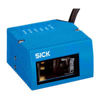
SICK CLV640 Technical Information (42 pages)
Stationary Bar Code Scanners
Brand:
SICK
| Category:
Barcode Reader
| Size: 2 MB
Table of Contents
Table of Contents
3
About this Document
5
Information on the Technical Information
5
Explanation of Symbols
5
Safety Information
7
Intended Use
7
Improper Use
7
Cybersecurity
7
Configuration with Profile Programming
8
Hazard Warnings and Operational Safety
8
Laser Radiation
8
Product Description
12
Product ID
12
Type Label
12
Design
13
Scope of Delivery
15
Differences: Devices in IP65 Standard Housing and Devices in IP69K Protective Housing
17
Reading Fields
18
Transport and Storage
21
Bar Code Scanners Clv62X, Clv63X and Clv64X with IP69K Protective Housing
21
Mounting
22
Overview of Mounting Procedure
22
Mounting Requirements
22
Mounting Options
22
Mounting the Protective Double Bushing on the Protective Housing
23
Assembly with Use of the Ethernet Connection
23
Assembly Without Use of the Ethernet Connection
25
Electrical Installation
28
Safety
28
Notes on Electrical Installation
28
Prerequisites for Safe Operation of the Device in a System
29
Pin Assignment of the Connections
29
Technical Data
31
Clv62X Bar Code Scanner in the IP69K Protective Housing
31
Clv63X Bar Code Scanner in the IP69K Protective Housing
33
Clv64X Bar Code Scanner in the IP69K Protective Housing
36
Accessories
40
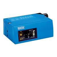
SICK CLV640 Technical Information (36 pages)
IP69K Protective Housing
Brand:
SICK
| Category:
Barcode Reader
| Size: 2 MB
Table of Contents
Table of Contents
3
1 About this Document
4
Information on the Technical Information
4
Explanation of Symbols
4
2 Safety Information
6
Intended Use
6
Improper Use
6
Hazard Warnings and Operational Safety
6
Laser Radiation
6
3 Product Description
10
Product ID
10
Type Label
10
Design
11
Scope of Delivery
13
Differences between Devices in IP65 Standard Housing and Devices in IP69K Protective Housing
14
Reading Fields
15
4 Transport and Storage
18
Bar Code Scanners Clv62X, Clv63X and Clv64X with IP69K Protective Housing
18
5 Mounting
19
Overview of Mounting Procedure
19
Mounting Requirements
19
Mounting Options
19
Mounting the Protective Double Bushing on the Protective Housing
20
Assembly with Use of the Ethernet Connection
20
Assembly Without Use of the Ethernet Connection
22
6 Electrical Installation
24
Safety
24
Notes on Electrical Installation
24
Prerequisites for Safe Operation of the Device in a System
25
Pin Assignment of the Connections
25
7 Technical Data
27
Bar Code Scanner Clv62X in IP69K Protective Housing
27
Bar Code Scanner Clv63X in IP69K Protective Housing
29
Bar Code Scanner Clv64X in IP69K Protective Housing
31
8 Accessories
34
Brackets
34
Cables
34
Advertisement
Advertisement
Related Products
SICK CLV64x
SICK CLV64 Series
SICK CLV65x
SICK CLV620
SICK CLV615
SICK CLV62 Series
SICK CLV632
SICK CLV601 U Series
SICK CLV601-1D200
SICK CLV610
SICK Categories
Accessories
Security Sensors
Measuring Instruments
Scanner
Barcode Reader
More SICK Manuals
Login
Sign In
OR
Sign in with Facebook
Sign in with Google
Upload manual
Upload from disk
Upload from URL