Sign In
Upload
Manuals
Brands
Shini Manuals
Water Heater
STM-HPW Series
Shini STM-HPW Series Water Heater Manuals
Manuals and User Guides for Shini STM-HPW Series Water Heater. We have
2
Shini STM-HPW Series Water Heater manuals available for free PDF download: Manual
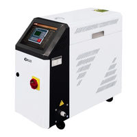
Shini STM-HPW Series Manual (65 pages)
Hi-Temp. Water Heater
Brand:
Shini
| Category:
Water Heater
| Size: 4 MB
Table of Contents
Table of Contents
3
1 General Description
7
Coding Principle
8
Feature
8
Technical Specifications
10
Specification
10
Pump Performance
11
Reference Formula of Mould Controllers Model Selection
11
Picture 1-1:Pump Performance
11
Safety Regulations
12
Safety Signs and Labels
12
Signs and Labels
13
Operation Regulations
14
Transportation and Storage of the Machine
15
Exemption Clause
17
2 Structure Characteristics and Working Principle
18
Working Principle
18
Picture 2-1:STM-PW Working Principle
18
Assembly Drawing
19
Assembly Drawing (STM-607-PW)
19
Picture 2-2:Assembly Drawing (STM-607-PW)
19
Parts List (STM-607-PW)
20
Assembly Drawing (STM-1220-PW)
21
Picture 2-2:Assembly Drawing (STM-1220-PW)
21
Parts List (STM-1220-PW)
22
Pump
23
Picture 2-3:Pump
23
Electrical Diagram
24
Main Circuit (STM-PW)(400V)
24
Picture 2-4:Main Circuit (STM-PW) (400V)
24
Control Circuit (STM-PW) (400V)
25
Picture 2-5:Control Circuit (STM-PW) (400V)
25
Electrical Components Layout (STM-PW) (400V)
26
Picture 2-6:Thermocouple and Terminal Layout (STM-PW) (400V)
26
Electrical Components List (STM-PW) (400V)
27
Main Circuit (STM-PW)(230V)
29
Picture 2-7:Main Circuit (STM-PW) (230V)
29
Control Circuit (STM-PW) (230V)
30
Picture 2-8:Control Circuit (STM-PW) (230V)
30
Electrical Components Layout (STM-PW) (230V)
31
Picture 2-9:Electrical Components Layout (STM-PW) (230V)
31
Thermocouple and Terminal Layout (STM-PW) (230V)
32
Picture 2-10:Thermocouple and Terminal Layout (STM-PW) (230V)
32
Electrical Components List (STM-PW) (230V)
33
Main Electrical Components Description
35
Overload Relay
35
Picture 2-11:Overload Relay
35
Operation Procedures
36
Installation Steps for Options Water Manifold (Dewaxing)
36
Installation Steps for Options Water Manifold (Welding)
36
3 Installation and Debugging
38
Installation Space
38
Mould and Water Coupling
38
Picture 3-1:Installation Space
38
Picture 3-2:Mould and Water Couplings 1
38
Power Supply
39
Picture 3-3:Mould and Water Couplings 2
39
Picture 3-4:Mould and Water Couplings 3
39
4 Operation Guide
40
Control Panel
40
Picture 4-1:Control Panel
40
Menu Introduction
43
Machine Startup
43
Pictute 4-2:Menu Outline
43
Picture 4-3: Main Power Switch
44
Picture 4-4: Initial Menu
44
Picture 4-5: Control Setting
45
Picture 4-6: Alarm Setting
46
Picture 4-7: Output Setting
47
Picture 4-8: Temperature Setting
48
Picture 4-9: Time Setting
49
Picture 4-10: Communication Setting
50
Picture 4-11: Equipment Setting
51
Parameter Reference Table
52
Picture 4-12: Operation Screen
52
Stop the Machine
53
5 Trouble-Shooting
55
6 Maintenance and Repair
57
Open the Covers
57
Picture 6-1:Open the Covers 1
57
Y Type Strainer
58
Picture 6-2:Open the Covers 2
58
Picture 6-3:Open the Covers 3
58
Picture 6-4:Y Type Strainer
58
Solenoid Valve
59
Pipe Heater
59
Picture 6-5:Solenoid Valve
59
Picture 6-6:Pipe Heater 1
59
Picture 6-7:Pipe Heater 2
59
Printed Circuit Board
60
Picture 6-8:Pipe Heater 3
60
Displayer Terminal Connecting Diagram
63
Maintenance Schedule
64
About the Machine
64
Installation & Inspection
64
Daily Checking
64
Weekly Checking
64
Trimonthly Checking
64
Half-Yearly Checking
64
Yearly Checking
65
Year Checking
65
Advertisement
Shini STM-HPW Series Manual (50 pages)
High Temp. Water Heater
Brand:
Shini
| Category:
Water Heater
| Size: 1 MB
Table of Contents
Table of Contents
3
1 General Description
7
Coding Principle
8
Feature
8
Technical Specifications
10
Specification
10
Pump Performance
11
Reference Formula of Mould Controllers Model Selection
11
Picture 1-1:Pump Performance
11
Safety Regulations
12
Safety Signs and Labels
12
Signs and Labels
13
Operation Regulations
14
Transportation and Storage of the Machine
15
Exemption Clause
17
2 Structure Characteristics and Working Principle
18
Working Principle
18
Picture 2-1:STM-HPW Working Principle
18
Assembly Drawing
19
Assembly Drawing (STM-940-HPW)
19
Picture 2-2:Assembly Drawing (STM-940-HPW)
19
Parts List (STM-940-HPW)
20
Pump
21
Picture 2-3:Pump
21
Electrical Diagram
22
Main Circuit (STM-940HPW 230V)
22
Picture 2-4:Main Circuit (STM-940HPW 230V)
22
Control Circuit (STM-940HPW 230V)
23
Picture 2-5:Control Circuit (STM-HPW 230V)
23
Thermocouple and Terminal Layout (STM-940HPW 230V)
24
Picture 2-6:Thermocouple and Terminal Layout (STM-HPW 230V)
24
Electrical Components Layout (STM-940HPW 230V)
25
Picture 2-7:Electrical Components Layout (STM-HPW 230V)
25
Electrical Components List (STM-940HPW 230V)
26
Main Circuit (STM-940HPW 400V)
27
Picture 2-8:Main Circuit (STM-940HPW 400V)
27
Control Circuit (STM-940HPW 400V)
28
Picture 2-9:Control Circuit (STM-HPW 400V)
28
Thermocouple and Terminal Layout (STM-940HPW 230V)
29
Picture 2-10:Thermocouple and Terminal Layout (STM-HPW 400V)
29
Electrical Components Layout (STM-940HPW 400V)
30
Picture 2-11:Electrical Components Layout (STM-HPW 400V)
30
Electrical Components List (STM-940HPW 400V)
31
Main Electrical Components Description
32
Overload Relay
32
Picture 2-12:Overload Relay
32
Operation Procedures
33
Installation Steps for Options Water Manifold (Dewaxing)
33
Installation Steps for Options Water Manifold (Welding)
33
3 Installation and Debugging
35
Installation Space
35
Mould and Water Coupling
35
Picture 3-1:Installation Space
35
Picture 3-2:Mould and Water Couplings 1
35
Power Supply
36
Picture 3-3:Mould and Water Couplings 2
36
Picture 3-4:Mould and Water Couplings 3
36
4 Operation Guide
37
Control Panel
37
Picture 4-1:Control Panel
37
Machine Startup
38
Picture 4-2:Machine Startup 1
39
Picture 4-3:Machine Startup 2
39
Stop the Machine
40
Temperature Controller
40
Temperature Controller Display
40
Picture 4-4:Temperature Controller Panel
40
Keys on Control Panel
41
Choose a Parameter
41
Comfirm Your Setting
42
Picture 4-5:Choose a Parameter
42
5 Trouble-Shooting
43
6 Maintenance and Repair
45
Open the Covers
45
Picture 6-1:Open the Covers 1
45
Y Type Strainer
46
Picture 6-2:Open the Covers 2
46
Picture 6-3:Open the Covers 3
46
Picture 6-4:Y Type Strainer
46
Solenoid Valve
47
Pipe Heater
47
Picture 6-5:Solenoid Valve
47
Picture 6-6:Pipe Heater 1
47
Picture 6-7:Pipe Heater 2
47
Displayer Terminal Connecting Diagram
48
Picture 6-8:Pipe Heater 3
48
Maintenance Schedule
49
About the Machine
49
Installation & Inspection
49
Daily Checking
49
Weekly Checking
49
Trimonthly Checking
49
Half-Yearly Checking
49
Yearly Checking
50
Year Checking
50
Advertisement
Related Products
Shini STM-W
Shini STM-607W
Shini STM-1220W
Shini STM-940HPW
Shini STM-1213-HPW
Shini STM-1220-PW
Shini STM-910WD
Shini STM-WF Series
Shini STM-PW-D Series
Shini STM-PW
Shini Categories
Industrial Equipment
Dryer
Chiller
Water Heater
Heater
More Shini Manuals
Login
Sign In
OR
Sign in with Facebook
Sign in with Google
Upload manual
Upload from disk
Upload from URL