Sign In
Upload
Manuals
Brands
Shini Manuals
Water Heater
STM-607W
Shini STM-607W Manuals
Manuals and User Guides for Shini STM-607W. We have
3
Shini STM-607W manuals available for free PDF download: Manual
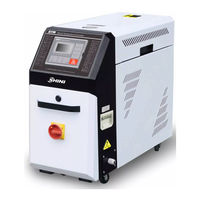
Shini STM-607W Manual (107 pages)
Brand:
Shini
| Category:
Water Heater
| Size: 8 MB
Table of Contents
Table of Contents
3
1 General Description
9
Coding Principle
10
Feature
10
Technical Specifications
12
Specification
12
Pump Performance
13
Reference Formula of Mould Controllers Model Selection
13
Safety Regulations
14
Safety Signs and Labels
14
Signs and Labels
15
Operation Regulations
16
Exemption Clause
17
2 Structure Characteristics and Working Principle
18
Main Functions
18
Working Principle
18
Picture 2-1:STM-W Working Principle
18
Assembly Drawing
20
Assembly Drawing (STM-607W/910W)
20
Picture 2-2:Assembly Drawing (STM-607W/910W)
20
Parts List (STM-607W/910W)
21
Assembly Drawing (STM-1220W)
22
Picture 2-3:Assembly Drawing (STM-1220W)
22
Parts List (STM-1220W)
23
Assembly Drawing (STM-2440W)
24
Picture 2-4:Assembly Drawing (STM-2440W)
24
Parts List (STM-2440W)
25
Assembly Drawing (STM-3650W)
26
Picture 2-5:Assembly Drawing (STM-3650W)
26
Parts List (STM-3650W)
27
Pump
28
Picture 2-6:Pump
28
Electrical Diagram
29
Main Circuit (STM-607W~1220W 400V)
29
Picture 2-7:Main Circuit (STM-607W~1220W 400V)
29
Control Circuit (STM-607W~1220W 400V)
30
Picture 2-8:Control Circuit (STM-607W~1220W 400V)
30
Electrical Components Layout (STM-607W~1220W 400V)
31
Picture 2-9:Thermocouple and Terminal Layout (STM-607W~1220W 400V)
31
Electrical Components List (STM-607W~1220W 400V)
32
Table 2-6:Electrical Components List (STM-910W 400V)
33
Table 2-7:Electrical Components List (STM-1220W 400V)
34
Main Circuit (STM-607WA~1220WA 400V)
35
Picture 2-10:Main Circuit (STM-607WA~1220WA 400V)
35
Control Circuit (STM-607WA~1220WA 400V)
36
Picture 2-11:Control Circuit (STM-607WA~1220WA 400V)
36
Electrical Components Layout (STM-607WA~1220WA 400V)
37
Picture 2-12:Thermocouple and Terminal Layout (STM-607WA~1220WA 400V)
37
Electrical Components List (STM-607WA~1220WA 400V)
38
Table 2-9:Electrical Components List (STM-910WA 400V)
39
Table 2-10:Electrical Components List (STM-1220W 400V)
40
Main Circuit (STM-607W-D/910W-D 400V)
41
Picture 2-13:Main Circuit (STM-607W-D/910W-D 400V)
41
Control Circuit (STM-607W-D/910W-D 400V)
42
Picture 2-14:Control Circuit 1(STM-607W-D/910W-D 400V)
42
Picture 2-15:Control Circuit 2(STM-607W-D/910W-D 400V)
43
Electrical Components Layout (STM-607W-D/910W-D 400V)
44
Picture 2-16:Electrical Components Layout (STM-607W-D/910W-D 400V)
44
Thermocouple and Terminal Layout (STM-607W-D/910W-D 400V)
45
Picture 2-17:Thermocouple and Terminal Layout (STM-607W-D/910W-D 400V)
45
Electrical Components List (STM-607W-D/910W-D 400V)
46
Table 2-12:Electrical Components List (STM-910W-D 400V)
47
Main Circuit (STM-2440W 400V)
48
Picture 2-18:Main Circuit (STM-2440W 400V)
48
Control Circuit (STM-2440W 400V)
49
Picture 2-19:Control Circuit (STM-2440W 400V)
49
Thermocouple and Terminal Layout (STM-2440W 400V)
50
Picture 2-20:Thermocouple and Terminal Layout (STM-2440W 400V)
50
Electrical Components List (STM-2440W 400V)
51
Main Circuit (STM-3650W 400V)
52
Picture 2-21:Main Circuit 1(STM-3650W 400V)
52
Picture 2-22:Main Circuit 2(STM-3650W 400V)
53
Control Circuit (STM-3650W 400V)
54
Picture 2-23:Control Circuit (STM-3650W 400V)
54
Electrical Components Layout (STM-3650W 400V)
55
Picture 2-24:Electrical Components Layout (STM-3650W 400V)
55
Electrical Components List (STM-3650W 400V)
56
Main Circuit (STM-3650WA 400V)
57
Picture 2-25:Main Circuit 1(STM-3650WA 400V)
57
Control Circuit (STM-3650WA 400V)
58
Picture 2-26:Control Circuit (STM-3650WA 400V)
58
Electrical Components Layout (STM-3650WA 400V)
59
Picture 2-27:Electrical Components Layout (STM-3650WA 400V)
59
Electrical Components List (STM-3650WA 400V)
60
Main Circuit (STM-607W~1220W 230V)
61
Picture 2-28:Main Circuit (STM-607W~1220W 230V)
61
Control Circuit (STM-607W~1220W 230V)
62
Picture 2-29:Control Circuit (STM-607W~1220W 230V)
62
Electrical Components Layout (STM-607W~1220W 230V)
63
Picture 2-30:Thermocouple and Terminal Layout (STM-607W~1220W 230V)
63
Electrical Components List (STM-607W~1220W 230V)
64
Table 2-17:Electrical Components List (STM-910W 230V)
65
Table 2-18:Electrical Components List (STM-1220W 230V)
66
Main Circuit (STM-607WA~1220WA 230V)
67
Picture 2-31:Main Circuit (STM-607WA~1220WA 230V)
67
Control Circuit (STM-607WA~1220WA 230V)
68
Picture 2-32:Control Circuit (STM-607WA~1220WA 230V)
68
Electrical Components Layout (STM-607WA~1220WA 230V)
69
Picture 2-33:Thermocouple and Terminal Layout (STM-607WA~1220WA 230V)
69
Electrical Components List (STM-607WA~1220WA 230V)
70
Table 2-20:Electrical Components List (STM-910WA 230V)
71
Table 2-21:Electrical Components List (STM-1220WA 230V)
72
Main Circuit (STM-3650WA 230V)
73
Picture 2-34:Main Circuit (STM-3650WA 230V)
73
Control Circuit (STM-3650WA 230V)
74
Picture 2-35:Control Circuit (STM-3650WA 230V)
74
Electrical Components Layout (STM-3650WA 230V)
75
Picture 2-36:Thermocouple and Terminal Layout (STM-3650WA 230V)
75
Electrical Components List (STM-3650WA 230V)
76
Main Electrical Components Description
77
Overload Relay
77
Picture 2-37:Overload Relay
77
Operation Procedures
78
Installation Steps for Options Water Manifold (Dewaxing)
78
Installation Steps for Options Water Manifold (Welding)
78
Installation Steps for Function of Water Drainage Via. Air Blowing
79
3 Installation and Debugging
80
Installation Space
80
Mould and Water Coupling
80
Picture 3-1:Installation Space
80
Picture 3-2:Mould and Water Couplings 1
80
Power Supply
81
Picture 3-3:Mould and Water Couplings 2
81
Picture 3-4:Mould and Water Couplings 3
81
4 Operation Guide
82
Control Panel
82
Picture 4-1:Control Panel
82
Table 4-2:Error Type
84
Machine Startup
85
Menu Introduction
85
Pictute 4-2:Menu Outline
85
Picture 4-3: Main Power Switch
86
Picture 4-4: Initial Menu
86
Picture 4-5: Control Setting
87
Picture 4-6: Alarm Setting
88
Picture 4-7: Output Setting
89
Picture 4-8: Temperature Setting
90
Picture 4-9: Time Setting
91
Picture 4-10: Communication Setting
92
Picture 4-11: Equipment Setting
93
Parameter Reference Table
94
Picture 4-12: Operation Screen
94
Stop the Machine
96
5 Trouble-Shooting
97
6 Maintenance and Repair
99
Open the Covers
99
Picture 6-1:Open the Covers 1
99
Y Type Strainer
100
Picture 6-2:Open the Covers 2
100
Picture 6-3:Open the Covers 3
100
Picture 6-4:Y Type Strainer
100
Solenoid Valve
101
Pipe Heater
101
Picture 6-5:Solenoid Valve
101
Picture 6-6:Pipe Heater 1
101
By-Pass Globe Valve
102
Printed Circuit Board
102
Picture 6-7:Pipe Heater 2
102
Picture 6-8:Pipe Heater 3
102
Picture 6-9:By-Pass Globe Valve
102
Displayer Terminal Connecting Diagram
105
Maintenance Schedule
106
About the Machine
106
Installation & Inspection
106
Daily Checking
106
Weekly Checking
106
Trimonthly Checking
106
Half-Yearly Checking
106
Yearly Checking
107
Advertisement
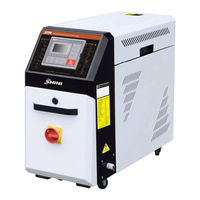
Shini STM-607W Manual (48 pages)
Brand:
Shini
| Category:
Water Heater
| Size: 3 MB
Table of Contents
Table of Contents
3
General Description
7
Coding Principle
8
Feature
8
Options
8
Technical Specifications
10
Specification
10
Pump Performance
10
Picture 1-1: Pump Performance
10
Reference Formula of Mould Controllers Model Selection
11
Safety Regulations
12
Safety Signs and Labels
12
Signs and Labels
13
Operation Regulations
15
Exemption Clause
16
Structure Characteristics and Working Principle
17
Main Functions
17
Working Principle
17
Picture 2-1: Working Principle
17
Installation and Debugging
19
Installation Space
19
Mould and Water Coupling
19
Picture 3-1: Installation Space
19
Picture 3-2: Mould and Water Couplings 1
19
Power Supply
20
Picture 3-3: Mould and Water Couplings 2
20
Picture 3-4: Mould and Water Couplings 3
20
Options Installation
21
Installation Steps for Options Water Manifold (Dewaxing)
21
Installation Steps for Options Water Manifold (Welding)
21
Installation Steps for Function of Water Drainage Via. Air Blowing
22
Operation Guide
23
Control Panel
23
Picture 4-1: Control Panel
23
Menu Introduction
26
Pictute 4-2: Menu Outline
26
Machine Startup
27
Picture 4-3: Main Power Switch
27
Picture 4-4: Initial Menu
27
Picture 4-5: Control Setting Screen
28
Picture 4-6: Alarm Setting Screen
29
Picture 4-7: Output Setting Screen
30
Picture 4-8: Temperature Setting Screen
32
Stop the Machine
37
Trouble-Shooting
38
Maintenance and Repair
40
Open the Covers
41
Picture 6-1: Open the Covers 1
41
Picture 6-2: Open the Covers 2
41
Picture 6-3: Open the Covers 3
41
Y Type Strainer
42
Solenoid Valve
42
Picture 6-4: y Type Strainer
42
Picture 6-5: Solenoid Valve
42
Pipe Heater
43
By-Pass Globe Valve
43
Picture 6-6: Pipe Heater 1
43
Picture 6-7: Pipe Heater 2
43
Picture 6-8: By-Pass Globe Valve
43
Printed Circuit Board
44
Displayer Terminal Connecting Diagram
46
Maintenance Schedule
47
About the Machine
47
Installation & Inspection
47
Daily Checking
47
Weekly Checking
47
Trimonthly Checking
47
Half-Yearly Checking
47
Yearly Checking
48
Year Checking
48
Shini STM-607W Manual (47 pages)
Dual-purpose Water/Oil Heater
Brand:
Shini
| Category:
Heater
| Size: 3 MB
Table of Contents
Table of Contents
3
1 General Description
7
Coding Principle
8
Feature
8
Accessory Option
8
Technical Specifications
10
Specification
10
Pump Performance
10
Picture 1-1: Pump Performance
10
Reference Formula of Mould Controllers Model Selection
11
Safety Regulations
11
Safety Signs and Labels
11
Signs and Labels
12
Operation Regulations
14
Transportation and Storage of the Machine
14
Exemption Clause
16
2 Structure Characteristics and Working Principle
17
Main Functions
17
Working Principle
17
Picture 2-1: Working Principle
17
3 Installation and Debugging
19
Installation Space
19
Mould and Water Coupling
19
Picture 3-1: Installation Space
19
Picture 3-2: Mould and Water Coupling 1
19
Power Supply
20
Picture 3-3: Mould and Water Coupling 2
20
Picture 3-4: Mould and Water Coupling 3
20
Options Installation
21
Installation Steps for Options Water Manifold (Dewaxing)
21
Installation Steps for Options Water Manifold (Welding)
21
4 Operation Guide
23
Control Panel
23
Picture 4-1: Control Panel
23
Menu Introduction
26
Pictute 4-2: Menu Outline
26
Machine Startup
27
Picture 4-3: Main Power Switch
27
Picture 4-4: Initial Menu
27
Picture 4-5: Control Setting Screen
28
Picture 4-6: Alarm Setting Screen
29
Picture 4-7: Output Setting Screen
30
Picture 4-8: Temperature Setting Screen
32
Stop the Machine
37
5 Trouble-Shooting
38
6 Maintenance and Repair
40
Open the Covers
41
Y Type Strainer
41
Picture 6-1: Open the Covers 1
41
Picture 6-2: Open the Covers 2
41
Solenoid Valve
42
Picture 6-3: y Type Strainer
42
Picture 6-4: Solenoid Valve
42
Printed Circuit Board
43
Displayer Terminal Connecting Diagram
45
Maintenance Schedule
46
About the Machine
46
Installation & Inspection
46
Daily Checking
46
Weekly Checking
46
Trimonthly Checking
46
Half-Yearly Checking
46
Yearly Checking
47
Year Checking
47
Advertisement
Advertisement
Related Products
Shini STM-607-HPW
Shini STM-607-PW
Shini STM-607WD
Shini STM-607WF
Shini STM-607PW-D
Shini STM-PW series
Shini STM-W Series
Shini STM-910W
Shini STM-2440W
Shini STM-913-HPW
Shini Categories
Industrial Equipment
Dryer
Chiller
Water Heater
Heater
More Shini Manuals
Login
Sign In
OR
Sign in with Facebook
Sign in with Google
Upload manual
Upload from disk
Upload from URL