Sign In
Upload
Manuals
Brands
Shini Manuals
Industrial Equipment
SAL-UGP Series
Shini SAL-UGP Series Manuals
Manuals and User Guides for Shini SAL-UGP Series. We have
2
Shini SAL-UGP Series manuals available for free PDF download: Manual
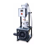
Shini SAL-UGP Series Manual (61 pages)
Vacuum Powder Loader
Brand:
Shini
| Category:
Industrial Equipment
| Size: 1 MB
Table of Contents
Table of Contents
3
1 General Description
7
Coding Principle
8
Feature
8
Technical Specifications
10
Technical Specifications (Main Unit)
10
The Outer Dimension of Hopper
10
Picture 1-1:SAL-1HP/2HP-UGP
10
Picture 1-2:SAL-3.5HP/5HP-UGP
10
Picture 1-3:SAL-7.5HP/10HP-UGP
10
The Installation Dimension of Hopper
11
Picture 1-4:SHR-P-12U
11
Picture 1-5:SHR-P-30U~SHR-P-90U
11
Picture 1-6:SHR-P-30U~SHR-P-90U
11
Specifications
12
Safety Regulations
14
Safety Signs and Labels
14
Signs and Labels
14
Exemption Clause
14
2 Structure Characteristics and Working Principle
16
Main Functions
16
SAL-UGP Working Principle
16
Picture 2-1:SAL-UGP Working Principle
16
Assembly Drawing
18
Assembly Drawing (SAL-1/2HP-UGP)
18
Picture 2-2:Assembly Drawing (SAL-1/2HP-UGP)
18
Parts List (SAL-1HP/2HP-UGP)
19
Assembly Drawing (SAL-3.5HP/5HP-UGP)
20
Picture 2-3:Assembly Drawing (SAL-3.5HP/5HP-UGP)
20
Parts List (SAL-3.5HP/5HP-UGP)
21
Assembly Drawing (SAL-7.5HP/10HP-UGP)
22
Picture 2-4:Assembly Drawing (SAL-7.5HP/10HP-UGP)
22
Parts List (SAL-7.5HP/10HP/15HP-UG)
23
Assembly Drawing of Storage Hopper with Plate Filter
24
Picture 2-5:Assembly Drawing of Storage Hopper with Plate Filter
24
Parts List of Storage Hopper with Plate Filter
25
Assembly Drawing of the Storage Hopper with Bag Filter
26
Picture 2-6:Assembly Drawing of the Storage Hopper with Bag Filter
26
Parts List of the Storage Hopper with Bag Filter
27
Electrical Diagram
28
Main Circuit (400V)
28
Picture 2-7:Main Circuit 1 (400V)
28
Picture 2-8:Main Circuit 2 (400V)
29
Electrical Components Layout (400V)
30
Picture 2-9:Electrical Components Layout (400V)
30
Electrical Components List (400V)
31
Main Circuit (230V)
37
Picture 2-10:Main Circuit 1 (230V)
37
Picture 2-11:Main Circuit 2 (230V)
38
Electrical Components Layout (230V)
39
Picture 2-12:Electrical Components Layout (230V)
39
Electrical Components List (230V)
40
Description of Electrical Components
46
Magnetic Proximity Switch
46
Main Electrical Components Description
46
Picture 2-13:Magnetic Proximity Switch
46
Picture 2-14:Overload Relay
46
3 Installation and Debugging
48
Installation Steps
48
Power Supply
48
4 Application and Operation
49
Start / Stop of the Machine
49
Keys on the Control Panel
49
Parameter Setting
49
Enter Basic Setting Mode
49
Picture 4-1:Keys on the Control Panel
49
Modify a Parameter
50
Finish Parameter Setting
50
Basic Parameter List
51
Process Setting
51
Enter into Process Setting Mode
51
Modify a Parameter
52
Finish Parameter Setting
52
Process Parameter List
52
Special Process Setting
53
Enter into Special Step Setting Mode
53
Modify a Parameter
53
Finish Parameter Setting
54
Parameter List of Special Process Setting
54
Explanation of Operation Procedures
55
Operation Procedures
55
Alarms
56
5 Trouble-Shooting
58
6 Maintenance and Repair
59
Material Hopper
59
Main Body
59
Advertisement
Shini SAL-UGP Series Manual (34 pages)
Vacuum Powder Loader
Brand:
Shini
| Category:
Vacuum Cleaner
| Size: 2 MB
Table of Contents
Table of Contents
3
General Description
5
Coding Principle
6
Feature
6
Technical Specifications
8
Dimension (Main Unit)
8
Specifications
8
Picture 1-1:Dimension
8
The Outer Dimension of Hopper
9
Picture 1-2:The Outer Dimension of Hopper
9
The Installation Dimension of Hopper
11
Picture 1-3:SHR-P-30U~SHR-P-90U
11
Safety Regulations
12
Safety Signs and Labels
12
Signs and Labels
12
Exemption Clause
13
Structure Characteristics and Working Principle
14
Main Functions
14
SAL-UGP Working Principle
14
Pic. 2-1:SAL-UGP Working Principle
14
Description of Electrical Components
15
Magnetic Proximity Switch
15
Picture 2-2:Magnetic Proximity Switch
15
Installation and Debugging
16
Machine Location
16
Installation Steps
16
Power Connection
17
Compressed Air Supply
17
Application and Operation
18
Control Panel Description
18
Pic. 4-1:Description of Operation Panel Keys
18
Parameter Setting
20
Communication Parameter Setting
23
Alarm Procedure
23
Operaton Procedure Description
24
Data Resetting
25
Communication Address(Protocol Modbus-RTU
26
Trouble-Shooting
30
Maintenance and Repair
31
Material Hopper
31
Main Body
32
Reed Switch, Photoelectric Switch
32
Weekly Checking
32
Monthly Checking
33
Maintenance Schedule
33
About the Machine
33
Installation & Inspection
33
Daily Checking
33
Weekly Checking
33
Advertisement
Related Products
Shini SAL-U Series
Shini SAL-UG
Shini SAL-UG122 Series
Shini SAL-U-CA
Shini SAL-U-E
Shini SAL-U-EA
Shini SAL-800G2 Series
Shini SAL-900G2 Series
Shini SAL-10HP-UGP-D
Shini SAL-20HP-UG122 Series
Shini Categories
Industrial Equipment
Dryer
Chiller
Water Heater
Heater
More Shini Manuals
Login
Sign In
OR
Sign in with Facebook
Sign in with Google
Upload manual
Upload from disk
Upload from URL