Sign In
Upload
Manuals
Brands
Shimadzu Manuals
Security Sensors
RF-20A
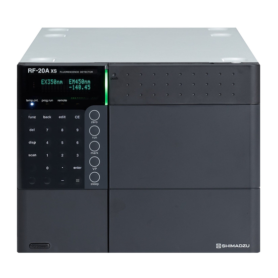
Shimadzu RF-20A Manuals
Manuals and User Guides for Shimadzu RF-20A. We have
1
Shimadzu RF-20A manual available for free PDF download: Service Manual
Shimadzu RF-20A Service Manual (91 pages)
Spectrofluorometric Detector
Brand:
Shimadzu
| Category:
Security Sensors
| Size: 6 MB
Table of Contents
Table of Contents
3
1 Introduction
7
Outline
7
2 Installation and Startup Modes
8
Checking Operation of the Lamp Cover Sensor
8
Checking Performance by the Raman Spectrum of Water (S/N CHECK)
8
Starting up in the FACTORY Mode
8
Starting up with the [Back] Key
8
3 Outline of Optical System
9
4 Exploded Views of Instrument
10
Main Unit
10
View of Main Unit
10
Used Units List
10
OPT Unit
11
Exploded View
11
Parts Used List
11
PCB Unit
12
Unit Diagram
12
Parts Used List
12
5 Replacing Parts and Upgrading ROM
13
Replacing the CPU Board
13
When the Existing EEPROM (M37) Is Normal
13
When the EEPROM (M37) Is Defective
13
Replacing the High-Voltage Cable
13
Replacing the Activated Carbon Pack and Replacement Cycle
14
Upgrading the ROM
14
6 Optical Adjustments
15
Flow Chart for Optical Adjustment
15
List of Jigs
17
Preparations for Adjustment
18
Rough-Adjustment of the Light Source Mirror (Oval Surface Mirror)
19
Adjusting the Excitation Grating
22
Adjusting the Photodiode Assembly (PD ASSY) and Beam Splitter
25
Fine-Adjustment of the Light Source Mirror (Oval Surface Mirror)
27
Adjusting Emission Mirror 1
29
Checking the Position of the EM Grating
32
Adjusting the EM Grating
34
Adjusting the Internal Mercury Lamp Reflection Mirror (RF-20AXS Only)
36
When Adjusting Using the Conventional "LM PULSE" (V1.05 and Earlier)
36
Automatic Adjustment Mode of Reflective Mirror (Motor) for Hg Lamps (V1.06)
37
When Adjusting Using Semi Auto Mode [LM ADJ] (V1.06 and Later)
38
7 Wavelength Calibration "FACTORY
39
Outline
39
Preparations
39
Wavelength Calibration Procedure
40
Procedure of Wavelength Accuracy Automatic Check
42
Judgment of Wavelength Accuracy and Display of Results
43
Wavelength Calibration Operation Procedure
43
8 Compensating Sensitivity (Eliminating Physical Differences between Instruments)
44
Compensating Sensitivity (SENS COMP)
44
Adjustment Using Peak Height of the Raman Spectrum of Water
44
Compensating and Verifying Sensitivity at the Factory (Reference)
44
Adjusting and Verifying Sensitivity
44
Jig Flow Line Diagram
44
Preparations
45
Adjusting SENS 1
45
Verifying the Sensitivity of SENS 1
45
Adjusting SENS 2
46
Verifying the Sensitivity of SENS 2
46
Adjusting SENS 3
47
Verifying the Sensitivity of SENS 3
47
9 Adjusting and Checking the Leak Sensor
48
Adjusting Sensitivity
48
Checking Operation of the Leak Sensor
48
10 FACTORY Parameters
49
FACTORY Parameter List
49
How to Use FACTORY Menu
53
Operation Procedure in the Temperature Test Mode [TEMP CHECK]
53
11 Error Messages and Remedying Errors
54
FATAL Messages
54
ALARM Messages
55
WARNING Messages
56
12 Electrical Circuit Diagrams
57
Block Diagram
57
CPU Board
58
SCHEMATIC, RF20-CPU Sheet 1/9
58
SCHEMATIC, RF20-CPU Sheet 2/9
59
SCHEMATIC, RF20-CPU Sheet 3/9
60
SCHEMATIC, RF20-CPU Sheet 4/9
61
SCHEMATIC, RF20-CPU Sheet 5/9
62
SCHEMATIC, RF20-CPU Sheet 6/9
63
SCHEMATIC, RF20-CPU Sheet 7/9
64
SCHEMATIC, RF20-CPU Sheet 8/9
65
SCHEMATIC, RF20-CPU Sheet 9/9
66
TEMP Circuit Board
67
SCHEMATIC, RF20-TEMP Sheet 1/3
67
SCHEMATIC, RF20-TEMP Sheet 2/3
68
SCHEMATIC, RF20-TEMP Sheet 3/3
69
LC-20A KEY-S Board
70
SCHEMATIC, LC20A-KEY-S Sheet 1/1
70
13 Maintenance Parts List
71
Consumable Parts List
71
Optical System Maintenance Parts List
71
Flow Cell/Piping Parts Maintenance Parts List
72
Electrical and Other Parts List
74
14 Flow Cell Unit
75
Standard Flow Cell Unit
75
Cell Structure
75
Parts Used List
75
Flow Cell for Semimicro (Option)
76
Specifications
76
Cell Structure
76
Semimicro Cell Maintenance Parts List
76
Flow Cell for Inert LC (Option)
77
Specifications
77
Cell Structure
77
Inert Cell Maintenance Parts List
77
15 Type of Photomultiplier (Option) and Replacement Procedure
78
Type and Settable Wavelength Range
78
Structure
78
Gain
78
Replacing the Photomultiplier
79
Overview of Replacement Procedure
79
Pre-Replacement Procedure
79
Photomultiplier Replacement Procedure
79
Calibrating the Wavelength after Photomultiplier Replacement
81
Wavelength Calibration Procedure
81
Compensating Sensitivity after Photomultiplier Replacement (Adjustment Using Peak Height of the Raman Spectrum of Water)
81
Preparation
81
Adjusting [Sens2]
81
Adjusting [Sens1]
82
Adjusting [Sens3]
82
16 Base ASSY, XS (Including Peltier Unit) Replacement Procedure
82
Checkpoint of a Base ASSY,XS
82
Replacement Procedure
82
Removing Front Panel ASSY
83
Removing Emission Monochromator
83
Removing Xenon Lamp
84
Removing All Cables Connecting to Optical System
84
Removing Xenon Power Supply Cable
85
Removing Power Supply Cable
85
Removing Three Screws for Fixing Optical System
86
Removing Optical System
86
Removing Four Screws for Fixing Base ASSY
87
Removing Photomultiplier Cable
87
Removing PMT Unit ASSY
89
Removing Base ASSY
89
Re-Assembling Base ASSY
90
Adjustment of Emission Monochromator Optical Axis
90
Wavelength Calibration
90
Disconnecting Peltier ASSY from Base ASSY, XS (for Reference)
91
Advertisement
Advertisement
Related Products
Shimadzu RID-10A
Shimadzu RF-20AXS
Shimadzu R-300
Shimadzu RC-300
Shimadzu ECD-2010 Exceed
Shimadzu FPD-2010
Shimadzu GC-2010
Shimadzu SPD-16
Shimadzu SPD-20A
Shimadzu SPD-20AV
Shimadzu Categories
Laboratory Equipment
Measuring Instruments
Scales
Security Sensors
Medical Equipment
More Shimadzu Manuals
Login
Sign In
OR
Sign in with Facebook
Sign in with Google
Upload manual
Upload from disk
Upload from URL