Sign In
Upload
Manuals
Brands
SEW-Eurodrive Manuals
Control Unit
MOVIPRO
SEW-Eurodrive MOVIPRO Manuals
Manuals and User Guides for SEW-Eurodrive MOVIPRO. We have
2
SEW-Eurodrive MOVIPRO manuals available for free PDF download: Manual, Addendum To The Operating Instructions
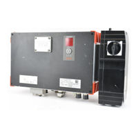
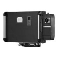
Sew Eurodrive MOVIPRO Manual (197 pages)
Brand:
Sew Eurodrive
| Category:
Controller
| Size: 16 MB
Table of Contents
Table of Contents
3
1 General Information
5
Structure of the Safety Notes
5
Meaning of the Signal Words
5
Structure of the Section-Related Safety Notes
5
How to Use this Documentation
5
Exclusion of Liability
6
General Safety Notes for Bus Systems
6
Safety Functions
6
Rights to Claim under Limited Warranty
6
Other Applicable Documentation
6
Hoist Applications
7
Copyright
7
Description
8
Drive Task
8
Benefits
8
2 Application Modules in MOVITOOLS ® Motionstudio
8
Application Modules for MOVIPRO ® SDC
8
Available Application Modules
9
Bus Positioning
9
Extended Bus Positioning
10
Modulo Positioning
11
Table Positioning
11
Sensor-Based Positioning
12
Automotive AMA0801
13
Startup Procedure
14
Check List for Startup
14
Preliminary Work
14
Unit Installation
15
Configuration of MOVIPRO
15
4 Installation Notes
16
Fieldbus Connection
16
Ethernet Fieldbus X4232_11 and X4232_12 (RJ45)
16
Ethernet Fieldbus X4233_11 and X4233_12 (M12)
17
Ethernet Connection
17
The Integrated Ethernet Switch
18
Auto-Crossing
18
Auto-Negotiation
18
Notes on Multi Cast Handling
18
TCP/IP Addressing and Subnetworks
19
Mac ID
19
IP Address
19
Network Classes
19
Subnet Mask
20
Standard Gateway
20
DHCP (Dynamic Host Configuration Protocol)
21
Setting the IP Address Parameters
21
Initial Startup
21
Changing the IP Address Parameters after Initial Startup
21
SEW Address Editor
22
Shielding and Routing the Bus Cables
22
Status and Error Messages
23
Unit Status
23
Inverter Status
24
Inverter Error
25
Status LED
25
Status LED S1 Ethernet/Ip and Modbus/Tcp
25
Status LED S2
26
Status LED S3
26
Ethernet/Ip – Configuration and Startup
27
Validity of the EDS File for MOVIPRO
27
Configuring the Master (Ethernet/Ip Scanner)
27
Process Data Exchange
28
Other Settings
30
Configuration Example in Rslogix 5000
30
Access to Unit Parameters
35
Reading Parameters
35
Writing Parameters
38
Create the Controller Tags
38
Access to Unit Parameters of the Integrated Power Section
40
6 Ethernet Industrial Protocol (Ethernet/Ip)
41
Introduction
41
Process Data Exchange
41
Timeout Response
41
CIP Object Directory
42
Class
42
Identity Object
42
Instance 1
42
Coding of Attribute 5 "Status"
43
Message Router Object
43
Supported Services
43
Assembly Object
44
Register Object
45
Description of the Parameter Channel
46
Instance 1 – SEW
48
Parameter Index
48
Parameter Object
48
Instance 2 – SEW Subindex
49
Instance 4 – SEW Subparameter 2
49
Instance 5 – SEW Read/Write
49
Vardata Object
50
TCP/IP Interface Object
51
Ethernet Link Object
52
Ethernet/Ip Return Codes
53
Return Codes of the Parameterization Via Explicit Messages
53
SEW-Specific Return Codes
53
General Error Codes
54
7 Configuration and Startup of Modbus/Tcp
57
Unit Description File for Modbus/Tcp
57
Configuration of the Master (Modbus Scanner)
57
Hardware Configuration
57
Settings for the Ethernet Component
58
Addressing the Drive Using IO Scanning
59
Configuration Examples in PL7 PRO
60
Data Exchange Via Modbus/Tcp – Examples
61
Writing and Reading Process Data
62
Parameter Access
64
8 Modbus Protocol (Modbus/Tcp)
66
Introduction
66
Mapping and Addressing
66
Access
67
Services (Function Codes)
67
Header
68
Protocol Structure
68
Service FC3 – Read Holding Registers
69
Service FC16 – Write Multiple Registers
70
Service FC23 – Read/Write Multiple Registers
71
Service FC43 – Read Device Identification
72
Connection Management
73
Dropping Connections
73
Sending Process Output Data (Requesting a Controlling Connection)
73
Parameter Access Via Modbus/Tcp
74
Timeout Monitoring
74
Procedure with FC16 and FC3
75
Procedure with FC23
75
Function Code-Data
76
MBAP Header
76
MOVILINK Parameter Channel
77
Error Codes (Exception Codes)
78
Check the Status LED S1 of MOVIPRO
79
Diagnostic Sequence
79
Operation on Ethernet/Ip and Modbus/Tcp – Error Diagnostics
79
Check the Status LED and the Status Display of the Master
80
Error Diagnostics
80
Fieldbus Timeout
80
10 Process Data Description
81
Overview of Process Data
81
MOVIPRO ® Control Word
81
MOVIPRO ® Status Word
82
10.4 Digital Inputs and Outputs
83
Speed-Controlled Drive
84
10.5 Process Data of Power Section
84
Setpoint Speed
87
Ramp
87
Status Word 1
87
Actual Speed
88
Active Current
88
"Bus Positioning" Application Module
88
"Extended Bus Positioning" Application Module
89
"Modulo Positioning" Application Module
90
"Table Positioning" Application Module
91
"Sensor-Based Positioning Via Bus" Application Module
91
"Automotive AMA0801" Application Module
92
Motionstudio – Operation
93
Tasks
93
Establishing Communication with Other Units
93
Executing Functions with the Units
93
11 MOVITOOLS ® Motionstudio - Operation
93
About MOVITOOLS ® Motionstudio
93
First Steps
94
Starting the Software and Creating a Project
94
Establishing Communication and Scanning the Network
94
Connection Mode
94
Offline Tools
95
Online Tools
95
Selecting the Communication Mode
96
Communication Via Ethernet
97
Connection of Pc/Laptop
97
Address Editor
98
Start the Address Editor
98
Adjusting Located Ethernet Stations to the Network
101
Configuring the Communication Channel Via Ethernet
102
Setting Communication Parameters for SMLP
103
Communication Parameters for SMLP
105
Parameterizing Units
106
Reading or Changing Unit Parameters
106
Executing Functions with the Units
106
Starting up Units (Online)
107
Encoder Configuration
108
Encoder Startup
108
12 MOVIPRO ® - Parameterization
108
Defining the Encoder Mounting
112
Measuring the Ratio
113
Completing the Encoder Startup
118
12.2 Motor Startup
119
Complete Startup
119
12.3 Storing Unit Data
124
"PFA-..." Power Section Parameter Overview
126
"PFA-..." Power Section Parameter Information
131
P00X Process Values
131
P0Xx Display Values
131
Symbols
131
P011 Operating
132
P012 Error Status
132
P016 Enable Hours
132
P01X Status Displays
132
P017 Work
133
P02X Analog Setpoints
133
P03X Binary Inputs of Basic Unit
133
P05X Binary Outputs of Basic Unit
133
P09X Bus Diagnostics
134
P13X / P14X Speed Ramps 1/2
134
P1Xx Setpoints/Ramp Generators
134
P139 / P149 Ramp Monitoring 1 / 2
136
P16X / P17X Fixed Setpoints 1 / 2
136
P20X Speed Control
136
P2Xx Controller Parameters
136
P205 Load Precontrol CFC
138
P206 Sampling Time N-Controller
138
P207 Load Precontrol VFC
138
P210 P Gain Hold Controller
138
P3Xx Motor Parameters
139
P304 Torque Limit
140
P321/P331 Boost
140
P32X/P33X Motor Adjustment 1/2
140
P34X Motor Protection
141
ON Servomotor
142
P344 Motor Protection Interval
143
P35X Motor Direction of Rotation
143
Setting Range: Self-Ventilation / Forced Cooling
143
P500/P502 Speed
144
P50X Speed Monitoring
144
P5Xx Monitoring Functions
144
P504 Encoder Monitoring Motor
145
P521 Mains off Response
145
P522 Phase Failure Monitoring
145
P530 Sensor Type
146
P531 Sensor Type
146
P53X Motor Temperature Protection
146
P54X Gear Unit/Motor Monitoring
146
P542 Response to Oil Aging/Warning
147
P543 Response to Oil Aging/Error
147
P544 Oil Aging/Overtemperature
147
P545 Oil Aging
147
P560 Current Limit
148
P561 Frequency a
148
P562 Current Limit
148
P564 Current Limit
148
12.5.7 P6Xx Terminal Assignment
149
P702 Motor Category
150
P70X Operating Modes
150
P7Xx Control Functions
150
P71X Standstill Current
151
P720/P723 Set-Point Stop Function
152
P72X Setpoint Stop Function
152
P730/P733 Brake Function
153
P73X Brake Function
153
P740/P742 Skip Window Center
154
P74X Speed Skip
154
P802 Factory Setting
155
P80X Setup
155
P8Xx Unit Functions
155
P803 Parameter Lock
156
P804 Reset Statistics Data
156
P82X Brake Operation
156
P83X Error Responses
156
P830 Response to ’External Error’
157
P834 Response to "Lag Error"
157
P835 Response to "TF Signal"
157
P839 Response to "Positioning Interruption"
157
P840 Manual Reset
158
P841 Auto Reset
158
P842 Restart Time
158
P84X Reset Behavior
158
P852 User-Defined
159
P862 / P863 PWM Fix
159
P86X Modulation
159
P87X Process Data Description
159
P876 PO Data Enable
160
P900 Reference Offset
161
P90X IPOS Reference Travel
161
P9Xx IPOS Parameters
161
CW End of the Reference Cam
162
Left Zero Pulse
162
Limit Switch Left
162
P903 Reference Travel Type
162
P904 Reference Travel to Zero Pulse
163
P905 Hiperface Offset (Motor)
163
P906 Cam Distance
163
P910 Gain X Controller
164
P915 Velocity Precontrol
164
P916 Ramp Type
164
P91X IPOS Travel Parameters
164
P917 Ramp Mode
165
P918 Bus Setpoint Source
165
P92X IPOS Monitoring
165
P922 Position Window
166
P923 Lag Error Window
166
P930 Override
166
P93X IPOS Special Functions
166
P938 IPOS Speed Task 2
167
P941 Source of Actual Position
167
P94X IPOS Encoder
167
P96X IPOS Modulo Function
167
P963 Modulo Encoder Resolution
168
13 Service
169
Unit Replacement
169
Notes on Replacing Units
169
Replacing Units
169
7-Segment Display
170
Replacing Incremental Encoders
171
Replacing Absolute Encoders
171
Replacing Linear Encoder Systems
171
13.2 Encoder Exchange
171
13.3 Service Unit
171
Status Display and LED
172
Ethernet Service Interface
172
MOVIPRO® SDC Error List
172
14 Additional Documentation
183
Index
184
Advertisement
SEW-Eurodrive MOVIPRO Addendum To The Operating Instructions (44 pages)
Accessories
Brand:
SEW-Eurodrive
| Category:
Control Unit
| Size: 7 MB
Table of Contents
Table of Contents
3
1 General Information
4
Use of this Documentation
4
Structure of the Safety Notes
4
Rights to Claim under Limited Warranty
5
Exclusion of Liability
5
Other Applicable Documentation
5
Copyright
5
2 Pzm2Xa-A
6
Type Designation
6
Nameplate
6
Power Interface Assignment
7
Basic Unit
7
Scope of Functions
8
Maintenance Switch
8
Power Interface - Mechanical Installation
9
Power Interface - Electrical Installation
11
Power Interfaces - Technical Data
16
3 Sensor/Actuator Box
18
Sensor/Actuator Box - Electrical Installation
19
Technical Data of the Sensor/Actuator Box
20
4 BW..-0..-0. External Braking Resistors
23
Braking Resistors - Mechanical Installation
24
Technical Data of the External Braking Resistors
28
5 Jumper Plug
33
6 Mounting Accessories
34
Handles
34
Mounting Brackets
35
7 Fan Subassembly
38
Mechanische Installation of Fan Subassembly
39
Index
40
Advertisement
Related Products
SEW-Eurodrive MOVIFIT basic
Sew Eurodrive MOVISAFE UCSxxB Series
Sew Eurodrive MOVIDRIVE MDA Series
Sew Eurodrive MOVIDRIVE MDP Series
Sew Eurodrive MOVIDRIVE MDD Series
Sew Eurodrive MOVITRAC LT Series
SEW-Eurodrive MOVISAFE DCS B Series
SEW-Eurodrive MOVIAXIS MXR
Sew Eurodrive MOVIDRIVE MDA90A-0120-503-X-S00
Sew Eurodrive MOVIDRIVE MDA90A-0320-503-X-S00
SEW-Eurodrive Categories
Industrial Equipment
DC Drives
Controller
Inverter
Engine
More SEW-Eurodrive Manuals
Login
Sign In
OR
Sign in with Facebook
Sign in with Google
Upload manual
Upload from disk
Upload from URL