Sign In
Upload
Manuals
Brands
Servomex Manuals
Measuring Instruments
SERVOPRO 4900
Servomex SERVOPRO 4900 Manuals
Manuals and User Guides for Servomex SERVOPRO 4900. We have
2
Servomex SERVOPRO 4900 manuals available for free PDF download: Installation And Operation Manual, Installation Manual
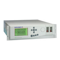
Servomex SERVOPRO 4900 Installation And Operation Manual (102 pages)
Continuous Emissions Analyser
Brand:
Servomex
| Category:
Analytical Instruments
| Size: 1 MB
Table of Contents
Table of Contents
8
Glossary
15
General Description
15
Location of Components
18
Introduction to the Xentra User Interface
18
Figure 1.1 Key Features of Xentra
18
The Xentra Measurement Display
19
Figure 1.2 Xentra Measurement Display
19
Figure 1.3 Xentra Process Variable Format
19
The Xentra Keypad
21
Figure 1.4 the Xentra Keypad
21
The Xentra Screen Icons
22
Figure 1.5 Xentra Status Icons
22
The Xentra Menu Display
23
Numeric Data Input
24
Password Protection
24
Transducer Site Numbering System
25
Output Numbering System
25
Transducer Full Scale Deflection
25
Technical Assistance and Spare Parts
26
Table 1.1 Transducer FSD Values
26
Section 2 Installation
27
Introduction
27
Unpacking and Inspection
27
Figure 2.1 Recommended Handling
28
Panel Mount Installation
29
Rack Slide Mounting Installation
30
Figure 2.2 Panel Mounting Detail
30
Figure 2.3 Rack Installation Exploded View
30
Table 2.1 Rack Mount Installation Kit Parts List
31
Electrical Power Connection
32
Figure 2.6 Fuse Holder Spring Clips
33
Signal Connections
34
Figure 2.7 Signal Socket Assembly
37
Table 2.2 Loose Socket Parts
37
Table 2.3 Signal Terminal Location PL1 to PL4
38
Serial Output Connection
39
Table 2.4 Signal Terminal Location PL5
39
Table 2.5 Serial Output Connections PL6
39
External Autocalibration Connection
40
Table 2.6 External Autocalibration Connections
40
Table 2.7 External Autocalibration Truth Table
40
Sample Stream Connection
41
Table 2.8 Sample Ports
41
Figure 2.8 Sample Gland Plate Without Auto Calibration
42
Figure 2.9 Sample Gland Plate with Internal Auto Calibration
42
Figure 2.10 Sample Gland Plate with External Auto Calibration
43
Figure 2.11 Typical Single Stream, Dual Gfx Configuration
43
Figure 2.12 Typical Dual Stream, Dual Gfx Configuration
44
Sample Gas Condition
45
Table 2.9 Sample Gas Conditions
45
Calibration Gas Sample Connection
46
Table 2.10 Recommended Calibration Gases
47
Table 2.11 Recommended Component Concentrations
47
Reading Flowmeters
48
Power up
48
Section 3 Initial Configuration
49
Setting Passwords
49
Table 3.1 Changing the Passwords
49
Setting Time and Date
50
Table 3.2 Setting Time and Date
50
Section 4 Calibration
51
Introduction to Calibration
51
Recommended Calibration Check Periods
52
Setting Low and High Calibration Tolerances
52
Table 4.1 Recommended Calibration Periods
52
Paramagnetic Transducer Low and High Manual Calibration
53
Table 4.2 Setting Low and High Calibration Tolerances
53
Table 4.3 Paramagnetic Low and High Calibration
54
Gfx Gas Transducer Low and High Manual Calibration
55
Table 4.4 Gfx Sensor Low and High Calibration
56
Manual Cal Check Low and High
57
Table 4.5 Low Cal Check
58
Table 4.6 High Cal Check
58
Auto Calibration Overview
59
Figure 4.1 Typical Autocalibration Sequence
59
Monitoring the Progress of Auto Calibration
61
Auto Calibration and Auto Check Setup
61
Figure 4.2 Screen Icons Indicating Autocalibration Progress
61
Table 4.7 Setting up Auto Calibration and Auto Check
63
Initiating Auto Calibration or Auto Check from Keypad
64
Initiating Auto Calibration or Auto Check by External Contact Closure
64
Table 4.8 Initiating Auto Cal or Check from Keypad
64
Aborting an Auto Calibration in Progress
65
Disabling Auto Calibration and Autocheck
65
Restarting Auto Calibration or Auto Check after Disabling
65
Table 4.9 Aborting Auto Cal or Auto Check
65
Scaling ( Calibration ) of the External Analogue Inputs
66
Table 4.10 External Analogue Input Scaling
66
Section 5 Main Configuration
67
Alarms
67
Table 5.1 Setting up Alarms
68
Allocation of Relays
69
Figure 5.1 Allocation of Relays
69
Table 5.2 Allocation of Relays
70
Analogue Outputs
71
Table 5.3 Clearing of Relay Assignment
71
Table 5.4 Analogue Output Span Limits
72
Table 5.5 Setting up Analogue Outputs
73
Table 5.6 Clearing an Analogue Output Assignment
74
Component Name Definition
75
Table 5.7 Component Name Definition
75
External Analogue Input Configuration
76
Table 5.8 External Analogue Input Definition
76
Defining and Selecting Measurement Displays
77
Table 5.9 Defining and Selecting Measurement Displays
77
Display Resolution
78
Response Time
78
Display Units
78
Table 5.10 Setting Response Time and Resolution
78
Calculation of Total Nitrogen Oxides (no ) Concentration
79
Table 5.11 Setting the no Conversion Parameters
80
Figure 5.2 Format of Serial Output Data Frame
81
Table 5.12 Serial Communications Parameters
81
Table 5.13 Setting the Serial Output Frame Frequency
81
Table 5.14 Setting the Serial Output Communications Parameters
83
Section 6 Review
85
Introduction to Review Section
85
Displaying Alarms Present
85
Displaying Faults Present
85
Table 6.1 Displaying Alarms Present
85
Table 6.2 Displaying Faults Present
85
Displaying Relay Configuration
86
Displaying Analogue Output Configuration
86
Table 6.3 Displaying Relay Configuration
86
Table 6.4 Displaying Analogue Output Configuration
87
Displaying Alarm Settings
88
Table 6.5 Displaying Alarm Settings
88
Displaying Analyser Identity
89
Displaying Alarm History
89
Table 6.6 Displaying Analyser Identity
89
Displaying Fault History
90
Displaying Calibration History
90
Table 6.7 Displaying Alarm History
90
Table 6.8 Displaying Fault History
90
Table 6.9 Displaying Paramagnetic Gas Sensor Calibration History
91
Displaying Diagnostics Information
92
Table 6.10 Displaying Diagnostic Information
92
Section 7 Routine Maintenance
93
Replacing Fan Filter Element
93
Replacing Sample Filter Element
93
Cleaning
93
Section 8 Fault Diagnosis
95
Introduction
95
Fault Diagnosis on the Pm1156 Transducer
95
Table 8.1 Fault Diagnosis on the Pm1156 Transducer
95
Fault Diagnosis on the Gfx 1210 Transducer
97
Table 8.2 Diagnostic Signals for the Pm1156 Transducer
97
Table 8.3 Fault Diagnosis on the Gfx1210 Transducer
97
Table 8.4 Diagnostic Signals for the Gfx 1210 Transducer
98
Fault Diagnosis with a Non-Functioning Display
99
Table 8.5 Fault Finding with Non Functioning Display
99
Section 9 Spares
101
Ordering Spares
101
Spare Parts List
101
Advertisement
Servomex SERVOPRO 4900 Installation Manual (74 pages)
Brand:
Servomex
| Category:
Measuring Instruments
| Size: 1 MB
Table of Contents
Table of Contents
5
Introduction
9
General Description
9
Location of Components
11
Figure 1.1: Key Features of 4000 Series Analyser
11
Transducer Site Numbering System
12
Output Numbering System
12
Transducer Full Scale Deflection
12
Conversion of Transducer Measuring Units
13
Table 1.1: Transducer FSD Values and Availability in Product Range
14
Calibration - General
15
Automatic Calibration Options
15
Table 1.2: Recommended Calibration Periods
15
Installation - General
17
Introduction
17
Unpacking and Inspection
18
Bench Mount Installation
18
Panel Mount Installation
18
Figure 2.1: Panel Mounting Detail
19
Rack Slide Mounting Installation
20
Figure 2.2: Rack Installation Exploded View
20
Installation - Electrical
23
Electrical Power Connection
23
Signal Connections
24
Figure 3.3: Signal Socket Assembly
25
Ma Output and Relay Output Connections
26
Table 3.1: Signal Terminal Location PL1 to PL4
27
Table 3.2: Optional External Autocalibration Connections PL8
27
Analogue Inputs
28
External Autocalibration Connection
29
Table 3.3: Signal Terminal Location PL5
29
Serial Data/Modbus Connection
30
Table 3.4: External Autocalibration Truth Table
30
Table 3.5: Serial Output Connections PL6
30
Continuous Mode
31
Table 3.6: Serial Output Data Frame, Start and End Sequences
31
Modbus Mode
32
Table 3.7: Serial Output Data Frame, Measurement Sequences
32
EMC Installation
33
Installation - Gas Connections
35
Introduction
35
Calibration Gases
35
Gfx Transducer Low and High Calibration
36
IR Transducer Low and High Calibration
36
Paramagnetic Transducer Low and High Calibration
36
Table 4.1: 4900D Calibration Gas Examples
36
Zirconia Transducer Low and High Calibration
37
Gas Connections
37
Figure 4.1: Sample Gland Plate Without Autocalibration
37
Figure 4.2: Sample Gland Plate with Internal Autocalibration
37
Table 4.2: 4100D and 4200D Sample Port Vs Transducer Type
38
Table 4.3: 4210D Sample Port Type
38
Reading Flowmeters
39
Autocalibration Overview
39
Table 4.4: 4900D Sample Port Type
39
Autocalibration Valve Installation
41
Figure 4.3: External Autocalibration - Parallel Systems
42
Figure 4.4: External Autocalibration - Stream Systems
43
Power up
44
Routine Maintenance
45
Replacing Fan Filter Element
45
Replacing the Sample Filter Element
45
Cleaning
46
Toxic/Flammable Samples - Routine Leak Test
46
Spares
47
Technical Specifications
49
Introduction
49
Generic 4000 Series Analyser Performance
49
Environmental Specifications
49
Power Supply
49
Design Standards
49
Analogue Outputs
50
Alarms
50
Serial Data/Modbus Connection
50
Analogue Inputs
50
Digital Inputs
50
Sample Wetted Materials
51
Table 7.1: Sample Wetted Materials
51
Table 7.2: Sample Wetted Materials, Continued
52
4100D Analyser Performance
53
Table 7.3: 4100D Performance Specification, Oxygen
54
Table 7.4: 4100D Performance Specification, Gfx
55
Table 7.5: Gfx Trace Measurement Cross Sensitivity Information
55
Table 7.6: 4100D Performance Specification, IR
56
Table 7.7: 152X Measurement Ranges in 4100D
56
4200D Analyser Performance
57
Table 7.8: 4200D Performance Specification, Oxygen and IR
58
Table 7.9: 152X Measurement Ranges in 4200D
58
Table 7.10: 4200D Performance Specification, Gfx
59
Table 7.11: Gfx Trace Measurement Cross Sensitivity Information
59
4210D Analyser Performance
60
Table 7.12: 4210D Performance Specification, Oxygen and IR
61
Table 7.13: 152X Measurement Ranges in 4210D
61
Table 7.14: 4210D Performance Specification, Gfx
62
Table 7.15: Gfx Trace Measurement Cross Sensitivity Information
62
4900D Analyser Performance
63
Table 7.16: 4900D Performance Specification, Oxygen and IR
64
Table 7.17: 152X Measurement Ranges in 4900D
64
Table 7.18A: 4900D Performance Specification, Gfx
65
Table 7.19A: 4900D Measurement Cross Sensitivity Information
65
Table 7.18B: 4900D Performance Specification, Gfx
66
Table 7.19B: 4900D Measurement Cross Sensitivity Information
66
Appendix A Effects of Variations in Sample
67
Composition
67
Appendix B Modbus Profile
71
Advertisement
Related Products
Servomex SERVOPRO 4000 Series
Servomex SERVOPRO 4100
Servomex SERVOPRO 4200
Servomex SERVOPRO 4210
Servomex SERVOPRO Plasma
Servomex SERVOPRO FID
Servomex SERVOPRO MultiExact
Servomex SERVOPRO Chroma
Servomex SERVOPRO k2001
Servomex 01440002D
Servomex Categories
Measuring Instruments
Analytical Instruments
Transmitter
Industrial Equipment
More Servomex Manuals
Login
Sign In
OR
Sign in with Facebook
Sign in with Google
Upload manual
Upload from disk
Upload from URL