Seg WIC1 Manuals
Manuals and User Guides for Seg WIC1. We have 5 Seg WIC1 manuals available for free PDF download: Manual, Reference Manual

Advertisement
Seg WIC1 Reference Manual (150 pages)
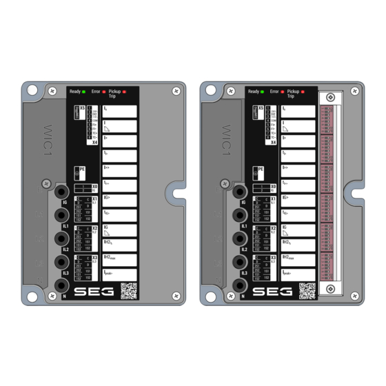
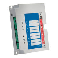
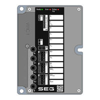
SELF-/DUAL-POWERED PROTECTION DEVICE
Brand: Seg
|
Category: Power distribution unit
|
Size: 1 MB
Table of Contents
Advertisement


Seg WIC1 Reference Manual (105 pages)
SELF-/DUAL-POWERED PROTECTION DEVICE
Brand: Seg
|
Category: Protection Device
|
Size: 1 MB
Table of Contents
Advertisement