Seg WI Series Manual
Hide thumbs
Also See for WI Series:
- Reference manual (153 pages) ,
- Manual (58 pages) ,
- Maintenance manual (7 pages)
Table of Contents
Advertisement
PROTECTION MADE SIMPLE.
WI Line
WIC1
SELF-/DUAL-POWERED PROTECTION DEVICE
Self-powered device, parameter settings via DiggiMEC / Smart view
WIC1-1
Self-powered device, parameter settings via DIP switches and/or DiggiMEC / Smart view
WIC1-2
Self-powered device, parameter settings via HEX switches and/or DiggiMEC / Smart view
WIC1-3
Dual-powered device, parameter settings via DiggiMEC / Smart view
WIC1-4
C
C
C
C
C
C
C
C
C
C
C
C
4
C
4
C
4
C
4
C
4
C
4
C
4
C
4
C
4
SELF-/DUAL-POWERED PROTECTION DEVICE
C
4
C
4
C
4
C
MANUAL WIC1-1.0-EN-MAN
Version: 1.0
Original document
English
Build 56554
Revision B
Advertisement
Table of Contents

Related Manuals for Seg WI Series


Summary of Contents for Seg WI Series
- Page 1 PROTECTION MADE SIMPLE. WI Line WIC1 SELF-/DUAL-POWERED PROTECTION DEVICE Self-powered device, parameter settings via DiggiMEC / Smart view WIC1-1 Self-powered device, parameter settings via DIP switches and/or DiggiMEC / Smart view WIC1-2 Self-powered device, parameter settings via HEX switches and/or DiggiMEC / Smart view WIC1-3 Dual-powered device, parameter settings via DiggiMEC / Smart view WIC1-4...
- Page 2 E-mail: support@SEGelectronics.de SEG Electronics GmbH reserves the right to update any portion of this publication at any time. Information provided by SEG Electronics GmbH is believed to be correct and reliable. However, no responsibility is assumed by SEG Electronics GmbH unless otherwise expressly undertaken.
-
Page 3: Table Of Contents
Table of Contents Table of Contents Safety Messages and Proper Use of the WIC1 ........11█... - Page 4 Table of Contents 2.13.1 Password ..............52█...
- Page 5 Table of Contents 3.8.1.1 WIC1-LED for “Pickup / TripCmd” ........... . 96█...
- Page 6 Table of Contents 4.3.2.1 Phase Overcurrent Protection – Settings via DiggiMEC or via Smart view ..... 142█ IH2 - Inrush Blocking .
- Page 7 Table of Contents 4.13 Integrated Backup Phase Overcurrent Protection ........174█...
- Page 8 Table of Contents Technical Data ..............204█...
- Page 9 Table of Contents 9.3.2 Housing ............... 223█...
- Page 10 Table of Contents 11.1.3.5 DIP-/HEX-Switch Settings for CT Type W6 ..........259█...
-
Page 11: Safety Messages And Proper Use Of The Wic1
1 Safety Messages and Proper Use of the WIC1 1.1 Important Definitions Safety Messages and Proper Use of the WIC1 Important Definitions The types of messages shown below serve the safety of life and limb as well as for the appropriate operating life of the device. -
Page 12: Proper Use Of The Device And Of This Manual
1 Safety Messages and Proper Use of the WIC1 1.2 Proper Use of the Device and of This Manual Proper Use of the Device and of This Manual CAUTION! Do not put the WIC1 in service until it has been configured and commissioned. Read the User Manual. - Page 13 The manufacturer cannot be held liable for any resulting damage, the user alone bears the risk for this. As to the appropriate use of the device: The technical data and tolerances specified by SEG have to be met. WARNING! Only the trip-coil output “TC+/−”...
- Page 14 1 Safety Messages and Proper Use of the WIC1 1.2 Proper Use of the Device and of This Manual WARNING! Ensure that the actual overcurrent settings comply with the technical and thermal limits of the device, the CTs and the application! Check the technical data (╚═▷...
-
Page 15: Personal Safety
1 Safety Messages and Proper Use of the WIC1 1.3 Personal Safety Personal Safety DANGER! Ignoring the following safety messages can result in death or serious injury or physical damage. DANGER! Only qualified electricians may install, commission, work or operate this device. All national standards –... -
Page 16: Important Information
1 Safety Messages and Proper Use of the WIC1 1.4 Important Information Important Information NOTICE! The devices are manufactured and delivered according to the order code specified by the customer. CAUTION! All electronic equipment is electrostatic-sensitive, some components more than others. To protect these components from electrostatic damage, you must take special precautions to minimize or eliminate electrostatic discharges. -
Page 17: Wic1 - Introduction And General Information
The WIC1 is a time-overcurrent relay that SEG has developed specifically for such requirements. The WIC1 is a CT-powered protection relay with minimal space requirement, that complies with the highest demands on a digital protection device. - Page 18 2 WIC1 – Introduction and General Information The ability of the protection system WIC1 to adapt to different primary currents makes it possible that it is used for all standard rated transformer loads and the different medium voltage operational voltages. The WIC1 is also available in device variants that can optionally be supplied with external power (so-called “Dual-Powered”...
-
Page 19: Basic Wiring Concept
2 WIC1 – Introduction and General Information 2.1 Basic Wiring Concept Basic Wiring Concept DiggiMEC USB Cable Current source, three phases plus wiring for ground current measurement Network Cable WIC1 X4–1...4: Digital Inputs And/or Power Supply − trip coil Test IL1 * Test IL2 * Test IL3 * Fig. - Page 20 2 WIC1 – Introduction and General Information 2.1 Basic Wiring Concept NOTICE! The assignment of the contacts X4‑1 … X4‑4 depends on the device variant. The separate document “WIC1 Wiring Diagrams” lists the exact contact assignments for each available typecode / order variant. It is recommended to look up this assignment for the WIC1 that is about to be wired.
-
Page 21: Operating Concept For The Wic1
2 WIC1 – Introduction and General Information 2.2 Operating Concept for the WIC1 Operating Concept for the WIC1 DiggiMEC RESET USB Cable Smart view File Device Edit View Settings Tools Window Help Shortcuts Device Data WIC1 Protection Para/- . - Operation Name Value Operation Device planning - . - - . -
Page 22: Supply Of A Wic1
2 WIC1 – Introduction and General Information 2.3 Supply of a WIC1 Supply of a WIC1 If a WIC1 is being operated in a typical application it is supplied via the CTs, and this is surely the normal case after commissioning. But for the case of completeness, we want to list all ways to supply a WIC1: Permanent Supply: •... - Page 23 2 WIC1 – Introduction and General Information 2.3 Supply of a WIC1 WARNING! Except for this special case of a short time signal (for an external trip), it is not permitted to feed any long-term or continuous voltage into the Digital Inputs. In other words, it is strongly discouraged to try to supply the WIC1 (for a considerable time) via the Digital Inputs.
-
Page 24: Wic1 Protection Features
2 WIC1 – Introduction and General Information 2.4 WIC1 Protection Features WIC1 Protection Features 2.4.1 Functional Overview WIC1 74TC 50BF 46BC Ipeak> SOTF Digital Inputs Measured Values * Status Display * Standard Option with DiggiMEC Fig. 4: Functional overview of the WIC1. WIC1 WIC1-1.0-EN-MAN... -
Page 25: Device Features
2 WIC1 – Introduction and General Information 2.4.2 Device Features 2.4.2 Device Features Features WIC1 Primary Application Type Self-/CT-Powered. (Device variant WIC1‑4 with optional ✓ auxiliary power supply) Mounting Type Housing suitable for mounting plate ✓ Inputs and Outputs WIC1 Inputs and Outputs of WIC1‑1 …... - Page 26 2 WIC1 – Introduction and General Information 2.4.2 Device Features Recorders ANSI / IEEE C37.2 WIC1 Fault recorder (non-volatile) ✓ Self-Supervision logging (messages about device-internal ✓ events – non-volatile) WIC1 WIC1-1.0-EN-MAN...
-
Page 27: Comments On The Manual
(provided by evidence). Information Concerning Liability and Warranty SEG does not accept any liability for damage resulting from conversions or changes carried out on the device or planning (projecting) work, parameter setting or adjustment changes done by the customer. -
Page 28: Symbols In Function Diagrams
2 WIC1 – Introduction and General Information 2.5.1 Symbols in Function Diagrams 2.5.1 Symbols in Function Diagrams Setting Values Prot . Nom voltage The upper box in the diagram on the left is the usual symbol of a setting value in a function diagram. - Page 29 2 WIC1 – Introduction and General Information 2.5.1 Symbols in Function Diagrams If the setting value of parameter »name . name . Function Function« is set to “Inactive”, then output 1 is Inactive active and output 2 is inactive. Active If the setting value of parameter »name .
- Page 30 2 WIC1 – Introduction and General Information 2.5.1 Symbols in Function Diagrams RS flip-flop with reset priority. Unchanged Edge-triggered counter. Band-pass filter (left: IH1, right: IH2). WIC1 WIC1-1.0-EN-MAN...
-
Page 31: Information About The Device
2 WIC1 – Introduction and General Information 2.6 Information About the Device Information About the Device Scope of Delivery The delivery scope includes: • (1) — The transportation box • • (2) — The protective device • • (3) — The test report •... -
Page 32: Order Form Of The Device
2 WIC1 – Introduction and General Information 2.6.1 Order Form of the Device 2.6.1 Order Form of the Device There are four different main variants of the WIC1 available, and these can have different additional order options: • WIC1‑1...: CT-Powered Protection Device without any switches, all settings are made •... -
Page 33: Order Form Of The Ct-Powered Device Types
2 WIC1 – Introduction and General Information 2.6.1.1 Order Form of the CT-Powered Device Types 2.6.1.1 Order Form of the CT-Powered Device Types CT Powered Time Overcurrent and Earth Current Relay WIC1 ‑ # Mounting form ↓ Parameter setting via DiggiMEC / Smart view Parameter setting via DIP switches, DiggiMEC or Smart view Parameter setting via HEX switches, DiggiMEC or... - Page 34 2 WIC1 – Introduction and General Information 2.6.1.1 Order Form of the CT-Powered Device Types CT Powered Time Overcurrent and Earth Current Relay WIC1 ‑ # Without communication protocol NOTICE! (**) Via DiggiMEC or Smart view (but not via DIP/HEX switches), it is possible to configure the device for either calculated or measured ground (earth) current.
-
Page 35: Order Form Of The Dual-Powered Wic1-4
2 WIC1 – Introduction and General Information 2.6.1.2 Order Form of the Dual-Powered WIC1‑4 2.6.1.2 Order Form of the Dual-Powered WIC1‑4 Dual-Powered Time Overcurrent and Earth Current Relay WIC1 ‑ # Mounting form ↓ Dual-Powered Powered Relay, parameter setting via DiggiMEC CT Type ↓... - Page 36 2 WIC1 – Introduction and General Information 2.6.1.2 Order Form of the Dual-Powered WIC1‑4 NOTICE! (**4) Via DiggiMEC or Smart view, it is possible to configure the device for either calculated or measured ground (earth) current. (***4) Via DiggiMEC or Smart view, it is possible to configure the device for either 50 Hz or 60 Hz nominal frequency.
-
Page 37: Order Form Of The Wic1-Compatible Current Transformers
2 WIC1 – Introduction and General Information 2.6.1.3 Order Form of the WIC1-Compatible Current Transformers 2.6.1.3 Order Form of the WIC1-Compatible Current Transformers WIC1 CTs Officially tested and recommended CTs for the WIC1 exist in two independent (electrically equivalent and interchangeable) construction types. Current Transformer (1 Piece) Short name + Prim‐... -
Page 38: Order Form Wi1Sz4
2 WIC1 – Introduction and General Information 2.6.1.4 Order Form WI1SZ4 2.6.1.4 Order Form WI1SZ4 Flag Indicator Article Number Small type, front 34 × 23 mm WI1SZ4 2.6.1.5 Order Form WI1SZ5 Flag Indicator Article Number Small type, front 34 × 23 mm, with bi-stable signal contacts 230 V AC, 3 A WI1SZ5 WIC1 WIC1-1.0-EN-MAN... -
Page 39: Order Form Of The Diggimec
2 WIC1 – Introduction and General Information 2.6.1.6 Order Form of the DiggiMEC 2.6.1.6 Order Form of the DiggiMEC Nano-HMI with Flag Indicators DiggiMEC Type ↓ Door mounting, 1 bi-stable relay / flag indicator Door mounting, 3 bi-stable relays / flag indicators WIC1-1.0-EN-MAN WIC1... -
Page 40: Settings - Operation
2 WIC1 – Introduction and General Information 2.7 Settings – Operation Settings – Operation Pursuant to the intended maintenance-free design there is no user interface with display. For the variants WIC1‑1 and WIC1‑4, all settings can only be done via the communication interface, by means of the DiggiMEC interface device. - Page 41 2 WIC1 – Introduction and General Information 2.7 Settings – Operation ◦ “Software” — DiggiMEC/Smart view settings shall be used. ◦ NOTICE! • In operating mode “Switches”, all the switches are permanently monitored, but • with a particular delay of approx. 10 seconds. This means: Only after no further switching has been done after 10 s, all (DIP/HEX) switch positions are evaluated.
-
Page 42: Smart View
2 WIC1 – Introduction and General Information 2.7.1 Smart view 2.7.1 Smart view Smart view is a parameter setting and evaluation software. It has a Technical Manual of its own. • Menu-controlled parameter setting incl. validity checks • • Offline configuration •... -
Page 43: Device Planning
2 WIC1 – Introduction and General Information 2.8 Device Planning Device Planning “Device Planning” means to change the functional range to a degree that suits the protection task to be fulfilled. There is a top-level menu item [Device planning] that is dedicated to this, and it makes essentially the following types of settings available: •... - Page 44 The manufacturer does not accept liability for any personal or material damage as a result of incorrect planning. Contact your SEG Customer Service representative for more information. SEG also offers configuration support as a service. WARNING! Beware of the inadvertent deactivating of protective functions/modules, because all the settings of a deativated module get lost (i. e.
-
Page 45: Modules, Settings, Signals And Values
2 WIC1 – Introduction and General Information 2.9 Modules, Settings, Signals and Values Modules, Settings, Signals and Values The WIC1 is a digital protection device that holds various data in its internal memory. Some data is meant to be changed by the user to adapt the functionality to the respective application, other data types are set by the device during run-time and are therefore read-only from the user's perspective. - Page 46 2 WIC1 – Introduction and General Information 2.9 Modules, Settings, Signals and Values that there are numerical parameters (e. g. overcurrent thresholds) and parameters which hold one option out of a selection list. These select options can either be fixed values, or they can be a signal (so that during run-time, the actual parameter value equals the state of the assigned signal).
-
Page 47: Measuring Values
2 WIC1 – Introduction and General Information 2.10 Measuring Values 2.10 Measuring Values Read out Measured Values In menu [Operation / Measured Values], both measured and calculated values can be viewed. The set of available measured values depends on the WIC1 variant. Display Options The user can define how measured values are to be displayed within the DiggiMEC HMI and Smart view:... - Page 48 2 WIC1 – Introduction and General Information 2.10 Measuring Values The CT type is set via the Direct Command »CT Type«. • »CT Type« = “Relative” — Display of relative current values. • • »CT Type« = “WE2 : 16 A ... 56 A”, … , “W6 : 256 A ... 896 A” — Display of primary •...
-
Page 49: Reset
2 WIC1 – Introduction and General Information 2.11 Reset 2.11 Reset The menu item “Reset” offers commands to reset the latching of a particular state (“selective reset”), and in addition there are some collective resets available: Type of Latched State Reset of Several States at the Same Selective Reset Time... - Page 50 2 WIC1 – Introduction and General Information 2.11 Reset • For the latching of DiggiMEC flag indicators / output relays, [Device Para / DiggiMEC / • FI / BO] »BO x latching« = “Latching w. Auto-Reset” (See also ╚═▷ “3.9.3.1 Latching”.) •...
-
Page 51: Reset To Factory Defaults
2 WIC1 – Introduction and General Information 2.12 Reset to Factory Defaults 2.12 Reset to Factory Defaults This Direct Control resets all parameters to their respective factory default: • [Service / General] »Factory Reset« • This is the same functionality as keeping the DiggiMEC key »✕« pressed during power-on, ╚═▷... -
Page 52: Security
2 WIC1 – Introduction and General Information 2.13 Security 2.13 Security Security-Related Messages Enter [Operation / Self-Supervision / Messages] »Messages« to access the list of Self- Supervision Messages. This is a special Recorder that collects device-internal messages of various types, including security-related events. It is recommended to check these entries from time to time. -
Page 53: Hardware
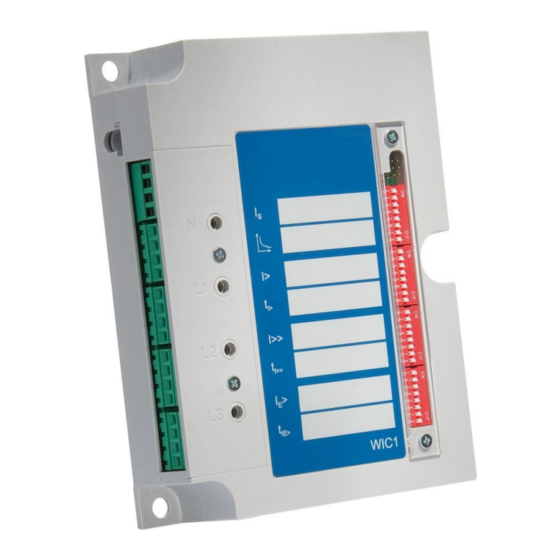
3 Hardware 3.1 Overview of Elements and Connectors Hardware Overview of Elements and Connectors NOTICE! The controls and connectors, that the WIC1 is fitted with, depends on the Order Form the WIC1. Front Side Test Sockets LEDs WIC1-1, WIC1-4 WIC1-2 WIC1-3 Fig. - Page 54 3 Hardware 3.1 Overview of Elements and Connectors LEDs System Ready System Error Pickup Trip LED 1 System Ready: This LED means: “Ready to Trip”. It is shining constantly green as soon as the WIC1 has (finished its booting process and and) loaded sufficient electrical energy for triggering the Trip impulse output.
- Page 55 3 Hardware 3.1 Overview of Elements and Connectors Lateral Terminals X0 / X1, X2, X3 Inputs Outputs Current measuring inputs Ethernet : RS485 DiggiMEC Fig. 6: Main groups of connectors at the side of the WIC1. The WIC1 has all connectors located at one side of the housing, so that it is convenient to connect the required cables.
-
Page 56: Terminals, Screws And Torques
3 Hardware 3.1.1 Terminals, Screws and Torques 3.1.1 Terminals, Screws and Torques CAUTION! Be careful. Do not overtighten the mountings nuts of the relay. Check the torque by means of a torque wrench with respect to the max. torque values in the table. Over- tightening the mounting nuts could cause personal injury or damage the relay. - Page 57 3 Hardware 3.1.1 Terminals, Screws and Torques Slot Tightening Screw Type Description Torques of the Screws Plastic cover for the DIP/HEX switches, fastened with two non-losable screws. WIC1-1.0-EN-MAN WIC1...
-
Page 58: Dimension Drawings
3 Hardware 3.2 Dimension Drawings Dimension Drawings 3.2.1 WIC1 Dimension Drawings All WIC1 variants are of the same standardized design. Therefore the dimension diagrams below are not meant to be restricted to a particular variant. [6.693] [3.346] [3.346] 16.07 [0.633] 7.20 6.50 [0.283]... - Page 59 3 Hardware 3.2.1 WIC1 Dimension Drawings 39.8 [1.567] 39.8 [1.567] 41.5 [1.634] [4.921] Fig. 8: WIC1, 2 sides view. All dimensions in mm, except dimensions in brackets [inch]. WIC1-1.0-EN-MAN WIC1...
-
Page 60: Diggimec Dimension Drawings
3 Hardware 3.2.2 DiggiMEC Dimension Drawings 3.2.2 DiggiMEC Dimension Drawings 102.0 [4.02] 96.0 [3.78] [2.09] [1.89] RESET Fig. 9: DiggiMEC, front view. All dimensions in mm, except dimensions in brackets [inch]. 55.8 [2.20] 49.8 [1.96] [1.89] [2.09] [0.98] 24.8 [1.22] [0.98] Fig. - Page 61 3 Hardware 3.2.2 DiggiMEC Dimension Drawings Installation Diagram – Cutout for Door Mounting of the DiggiMEC [3.62] Fig. 11: Door Cut-out. All dimensions in mm, except dimensions in brackets [inch]. The DiggiMEC can be mounted into a standard door cutout, that is already available by default with most cabinets.
-
Page 62: Dimension Drawings Of The Wic1-Compatible Current Transformers
3 Hardware 3.2.3 Dimension Drawings of the WIC1-Compatible Current Transformers 3.2.3 Dimension Drawings of the WIC1-Compatible Current Transformers 24.8 23.4 ⌀50 Fig. 12: Types WIC1W2AS1 – WIC1W5AS1 (panel mounting). WIC1 WIC1-1.0-EN-MAN... - Page 63 3 Hardware 3.2.3 Dimension Drawings of the WIC1-Compatible Current Transformers 24.8 23.4 ⌀50 Fig. 13: Types WIC1-CT2 – WIC1-CT5 (panel mounting). WIC1-1.0-EN-MAN WIC1...
- Page 64 3 Hardware 3.2.3 Dimension Drawings of the WIC1-Compatible Current Transformers Fig. 14: Type WIC1W6AS1 (panel mounting). WIC1 WIC1-1.0-EN-MAN...
-
Page 65: Dimension Drawing Of The Flag Indicator Wi1Sz5
3 Hardware 3.2.4 Dimension Drawing of the Flag Indicator WI1SZ5 3.2.4 Dimension Drawing of the Flag Indicator WI1SZ5 [0.1] 54.1 1000 [1.34] [39.37] [2.13] [A.] [D.] +0.5 Reset [B.] [C.] Fig. 15: Dimension Drawing for the WI1SZ5 flag indicator. (All dimensions in mm, except dimensions in brackets [inch].) [A.] Connection cables... -
Page 66: Wic1 - Installation And Wiring
3 Hardware 3.3 WIC1 – Installation and Wiring WIC1 – Installation and Wiring 3.3.1 Grounding Tightening Torque: 1.6 Nm (14.2 lb⋅in) Fig. 16: The grounding cable is fastened using the “PE” screw-nut. WARNING! The housing must be carefully grounded. • Connect a ground cable (protective earth, 4 to 6 mm² [AWG 11‒9], tightening •... -
Page 67: Nut "Pe" For Grounding
3 Hardware 3.3.1.1 Nut “PE” for Grounding 3.3.1.1 Nut “PE” for Grounding Fig. 17: Only the nut (1) and the washers (2), (3) may be loosened for mounting the grounding cable (PE). The grounding cable has to be furnished with a ring-terminal, that gets fastened between two washers, see the blue “PE”... -
Page 68: Selection Of A Wic1-Compatible Current Transformer
3 Hardware 3.3.2 Selection of a WIC1-Compatible Current Transformer 3.3.2 Selection of a WIC1-Compatible Current Transformer DANGER! The terminal block for connection to the current transformers is not a shorting block. Therefore always short-circuit current transformers before loosening the terminals. Ignoring this can result in dangerous voltages at the open contacts (up to dozens of kilovolts depending on the CT type). -
Page 69: Current Ranges Of The Wic1-Cts
3 Hardware 3.3.2.1 Current Ranges of the WIC1-CTs 3.3.2.1 Current Ranges of the WIC1-CTs 16 ... 56 A 56 ... 1120 A 50 : 1 16 ... 56 A 56 ... 1120 A 50 : 1 12 A 32 ... 112 A 112 ... -
Page 70: Ct Type We2
3 Hardware 3.3.2.2 CT Type WE2 3.3.2.2 CT Type WE2 In case of small values of the primary currents there is a special “E”-labeled CT available that features a mixed core based on MU metal and offers an optimized transmission characteristic: WIC1WE2AS1. - Page 71 3 Hardware 3.3.2.3 Selection of the CT Transformation Voltage Ratio The operating current should be in the rated CT current range. The WIC1 system can be loaded continuously up to 2.5 times of the upper rated CT current. (See ╚═▷ “3.3.2.1 Current Ranges of the WIC1-CTs”.) This has no effect on the measurement of the overload.
- Page 72 3 Hardware 3.3.2.3 Selection of the CT Transformation Voltage Ratio Quick Pick: Look up the CT Rated Power of the Transformer [kVA] 1000 1250 1600 2000 2500 3150 4000 5000 6300 10.0 11.0 13.8 15.0 20.0 22.0 24.0 30.0 1p min * In,min In,max W(E)2...
-
Page 73: Adapter Cts For 1 A
3 Hardware 3.3.3 Adapter CTs for 1 A 3.3.3 Adapter CTs for 1 A Only the special WIC1-compatible CTs are permitted for the phase current inputs. (See ╚═▷ “WIC1 CTs”.) The connection of common CTs – e. g. with 1 A secondary current – is not permitted. -
Page 74: Requirements For 1 A Standard Cts Being Used With Adapter Cts
3 Hardware 3.3.3.1 Requirements for 1 A Standard CTs being Used with Adapter CTs WIC1 Adapter CTs (internal) IL3,sec not connected IL2,sec not connected IL1,sec not connected IG,sec Fig. 21: Connection of 1 A standard CTs with adapter CTs in a Holmgreen circuit. The 1 A standard CTs, however, must fulfill some requirements so that the WIC1 can be safely supplied and the current can be measured with sufficient accuracy. - Page 75 3 Hardware 3.3.3.1 Requirements for 1 A Standard CTs being Used with Adapter CTs Impedance of the adapter CT plus WIC1 wic1 Accuracy limit factor Rated knee point e.m.f. Secondary terminal voltage of the standard CT When dimensioning the standard current transformers, the following conditions hold for the setting »CT .
- Page 76 3 Hardware 3.3.3.1 Requirements for 1 A Standard CTs being Used with Adapter CTs The impedance of the adapter CT plus WIC1 R has a non-linear dependency on wic1 the secondary current. Therefore the calculation of the minimum and of the maximum requirements use different values of R wic1 Example Calculation for a P/PR Class CT...
-
Page 77: Phase And Ground Current Measuring Inputs
3 Hardware 3.4 Phase and Ground Current Measuring Inputs Phase and Ground Current Measuring Inputs The WIC1 is provided with current measuring inputs for measuring the phase currents and – for the appropriate variants – one for measuring the earth (ground) current: •... - Page 78 3 Hardware 3.4 Phase and Ground Current Measuring Inputs The properties of the Current Transformers, in particular the rated CT current In, must also be specified in the settings, see ╚═▷ “11.1.3 Setting of the Rated CT current In”. The input for earth (ground) current measuring – if available – can be connected to a cable-type current transformer.
-
Page 79: Current Measuring Inputs For Wic1-Cts And Without Ground Current Input
3 Hardware 3.4.1 Current Measuring Inputs for WIC1-CTs and Without Ground Current Input 3.4.1 Current Measuring Inputs for WIC1-CTs and Without Ground Current Input Side View Front View WIC1 I> I> I>> I test I>> I test IG> IG> I test IG>>... -
Page 80: Current Measuring Inputs For Wic1-Cts With Ground Current Input
3 Hardware 3.4.2 Current Measuring Inputs for WIC1-CTs With Ground Current Input 3.4.2 Current Measuring Inputs for WIC1-CTs With Ground Current Input Side View Front View WIC1 I> I> I test I>> CT, 1 A I>> I test IG> IG> I test IG>>... -
Page 81: Current Measuring Inputs For Broad-Range-Cts And Without Ground Current Input
3 Hardware 3.4.3 Current Measuring Inputs for Broad-Range-CTs and Without Ground Current Input 3.4.3 Current Measuring Inputs for Broad-Range-CTs and Without Ground Current Input Side View Front View WIC1 I> I> I>> I>> I test I test IG> IG> I test IG>>... -
Page 82: Current Measuring Inputs For Broad-Range-Cts With Ground Current Input
3 Hardware 3.4.4 Current Measuring Inputs for Broad-Range-CTs With Ground Current Input 3.4.4 Current Measuring Inputs for Broad-Range-CTs With Ground Current Input Side View Front View WIC1 I> I> I test I>> CT, 1 A I>> I test IG> IG> I test IG>>... -
Page 83: Digital Input (Only Wic1-1
3 Hardware 3.5 Digital Input (only WIC1‑1… / WIC1‑2… / WIC1‑3…) Digital Input (only WIC1‑1… / WIC1‑2… / WIC1‑3…) not connected digital input DI2 Tightening Torque: 0.5 Nm (4.4 lb⋅in) Type of Input: Do Not Use Ext. Trip Or DI 230 VAC 115 VAC Fig. -
Page 84: Additional Power Supply And Digital Inputs (Wic1-4
3 Hardware 3.6 Additional Power Supply and Digital Inputs (WIC1‑4… only) Additional Power Supply and Digital Inputs (WIC1‑4… only) CAUTION! The Digital Inputs of the WIC1 are not potential-free, but always related to the “COM” terminal (see diagrams). Tightening Torque: 0.5 Nm (4.4 lb⋅in) Ext. - Page 85 3 Hardware 3.6 Additional Power Supply and Digital Inputs (WIC1‑4… only) ◦ Inputs for external trip signal and external reset signal (non-configurable ◦ inputs). ◦ 2 configurable digital inputs. ◦ (For the order options of the WIC1, see ╚═▷ “2.6.1 Order Form of the Device”.) Additional Power Supply The WIC1 does not require any aux.
-
Page 86: Outputs (Trip Coil, Flag Indicator, Relay Output)
3 Hardware 3.7 Outputs (Trip Coil, Flag Indicator, Relay Output) Outputs (Trip Coil, Flag Indicator, Relay Output) Output: Output: trip coil Flag Indicator or Relay Output Tightening Torque: 0.5 Nm (4.4 lb⋅in) Fig. 29: Terminal block X4: Outputs. Note that the WIC1‑4 has the outputs at X4‑5, X4‑6 labeled as “Out+/−”, instead of “FI+/−”. - Page 87 3 Hardware 3.7 Outputs (Trip Coil, Flag Indicator, Relay Output) Impulse Output for a Trip Coil The low-energy trip coil of the circuit breaker is connected to terminals TC+ and TC− of the terminal block X4. The trip energy is provided by a capacitor store integrated in the protection relay.
- Page 88 3 Hardware 3.7 Outputs (Trip Coil, Flag Indicator, Relay Output) A mechanical flag indicator WI1‑SZ4 or WI1‑SZ5 can visualize a signal, for example a trip signal, in a power-outage-safe manner. (In case of the WI1‑SZ5 this can be done potentially free via two changeover contacts.) Exception: A Backup Protection...
-
Page 89: Self-Supervision Contact For The Wic1-4
3 Hardware 3.7.1 Self-Supervision Contact for the WIC1‑4 3.7.1 Self-Supervision Contact for the WIC1‑4 Self-Supervision Contact Power Supply COM / L− Side View X4-1 X4-2 X4-3 − X4-4 X4-5 − X4-6 − X4-7 − X4-8 Output: trip coil Fig. 30: Connecting an external self-supervision contact. -
Page 90: Connecting A Flag Indicator To The Wic1
3 Hardware 3.7.2 Connecting a Flag Indicator to the WIC1 3.7.2 Connecting a Flag Indicator to the WIC1 0.5mm² [1.] Reset [2.] 0.5mm² Fig. 31: Connection diagram for the WI1SZ4 flag indicator. [1.] black cable, ⌀ = 0.5mm² [2.] black cable, ⌀ = 0.5mm² WIC1 WIC1-1.0-EN-MAN... - Page 91 3 Hardware 3.7.2 Connecting a Flag Indicator to the WIC1 orange [5.] violet [1.] [2.] [3.] [4.] [5.] [6.] [6.] Reset [9.] [8.] [7.] brown FI− [7.] Fig. 32: Connection diagram for the WI1SZ5 flag indicator. [1.] red cable, ⌀ = 0.5mm²: NC contact number 1 [2.] black cable, ⌀...
-
Page 92: Impulse Signal For The Flag Indicator
3 Hardware 3.7.3 Impulse Signal for the Flag Indicator 3.7.3 Impulse Signal for the Flag Indicator A flag indicator can be connected to terminals FI+/FI− (WIC1‑4: Out+/Out−) of the terminal block X4, e. g. for a power-safe signaling of a trip. The energy is provided by a capacitor store integrated in the WIC1 protection relay. -
Page 93: Input, Output And Led Settings
3 Hardware 3.8 Input, Output and LED Settings Input, Output and LED Settings 3.8.1 LEDs LED 2 System (Ready/Error) LED LED 3 System Ready System Error Pickup/ Trip RESET (* Configurable) WIC1 LEDs The WIC1 features one green LED and two red LEDs. •... - Page 94 3 Hardware 3.8.1 LEDs NOTICE! The green “System/Ready” LED has the fixed (non-configurable) meaning: “Ready to Trip”. This meaning is more strict than a simple “device is running”. Therefore it is possible (for example if the WIC1 is solely supplied via DiggiMEC-USB) that the WIC1 is running, so that you can configure it and/or read out measuring values, but the “System/Ready”...
- Page 95 Ready LED Error LED • Since only the backup protection is active the • WIC1 needs to be replaced as soon as possible, and you should contact SEG Support. DiggiMEC System-LED: Additional DiggiMEC-specific LED Signals DiggiMEC Two-Colored (Green+Red) System If the display is not available the DiggiMEC is not supplied with electricity, neither from the WIC1, nor via the USB interface from a connected PC.
- Page 96 3 Hardware 3.8.1.1 WIC1-LED for “Pickup / TripCmd” 3.8.1.1 WIC1-LED for “Pickup / TripCmd” The third LED WIC1 is labeled “Pickup / Trip” and has indeed a double functionality: • Blinking red — (General) Pickup. • Constant Red — Trip Command. Since there is no latching there is no need for a reset of the LED.
- Page 97 3 Hardware 3.8.1.3 Latching of the DiggiMEC LEDs • “No latching” – No latching, the status always follows the status of the assigned • signal. • “With latching” – With latching, i.e. the state remains active once the the assigned •...
- Page 98 3 Hardware 3.8.1.4 Latching of a DiggiMEC-LED with an Assigned Trip Signal 3.8.1.4 Latching of a DiggiMEC-LED with an Assigned Trip Signal Special case: Whenever a trip signal is assigned to a LEDx, the corresponding pickup signal gets assigned as well, with the following behavior: •...
- Page 99 3 Hardware 3.8.1.4 Latching of a DiggiMEC-LED with an Assigned Trip Signal DiggiMEC-LEDs wiLED_Y03 Settings: DiggiMEC . LED2 assign. = I> . Trip DiggiMEC . LED2 latching = With latching Reset I> . Pickup I> . Trip ✳ ✴ ✳ ✴...
- Page 100 3 Hardware 3.8.2 Configuration of the Digital Inputs 3.8.2 Configuration of the Digital Inputs Note that not all WIC1 variants feature configurable Digital Inputs. Please check the order options. Some WIC1 variants feature two configurable Digital Inputs, DI1 and DI2. (See also ╚═▷...
- Page 101 3 Hardware 3.8.3 Date and Time 3.8.3 Date and Time The WIC1 lacks a real-time clock. This is an intended construction aspect, because a real-time clock would have required a buffer battery and even communication protocols for time synchronization. The WIC1, however, has been designed to operate in a remote station for years without special maintenance (like exchanging a battery).
- Page 102 3 Hardware 3.9 DiggiMEC – Nano HMI with Flag Indicators and Output Relays DiggiMEC – Nano HMI with Flag Indicators and Output Relays The DiggiMEC is a remote HMI to be used in connection with a WIC1 (version 2) protection relay.
- Page 103 3 Hardware 3.9 DiggiMEC – Nano HMI with Flag Indicators and Output Relays CAUTION! Use an Ethernet cable CAT 3 (or better) with shielding for the connection between WIC1 and DiggiMEC. Crossover cables must not be used! Make sure that the connection cable between WIC1 and DiggiMEC is mounted according to all regulations! Respect the manufacturer's spcifications about permissible bending radii, and prevent defects by appropriate means such as cable conduits, e. g.
- Page 104 3 Hardware 3.9.1 Navigation – Operation 3.9.1 Navigation – Operation The following illustration shows the elements on the DiggiMEC front: 1, 2 System-LED System-LED LED2 LED2 LED3 LED3 RESET RESET DiggiMEC-A DiggiMEC-B 3.9.1.1 Front Panel Parts (1), (2), (3) Output Relays / Flag Indicators Each flag indicator is mechanically connected with a bistable output relay.
- Page 105 3 Hardware 3.9.1.1 Front Panel Parts • The connection to the WIC1 has been established. • • The WIC1 has successfully started all protection functions. • • The WIC1 has stored sufficient electrical energy to issue a trip impulse. • See also ╚═▷...
- Page 106 3 Hardware 3.9.1.1 Front Panel Parts An LED test is always also executed together with the reset: All LEDs flash in red color for (approx.) a second, then flash in green color for (approx.) a second. (8) »★« Key The “Favorites” key allows for an immediate access to often used menu branches. For the current Release, there is a fixed list of entries.
- Page 107 3 Hardware 3.9.1.2 Special Keys During Power-on 3.9.1.2 Special Keys During Power-on Some keys have a special functionality when being pressed during the power-on / boot process. • »↵« during power-on – After a confirmation dialog, the DiggiMEC enters a special •...
- Page 108 3 Hardware 3.9.1.3 Menu Structure 3.9.1.3 Menu Structure The menu structure offers the following top-level menu entries. You enter a menu branch with the »▶« key. The keys »▲« and »▼« let you navigate to the previous or next one. The key »◀«...
- Page 109 3 Hardware 3.9.1.3 Menu Structure Field settings 50/60 Usually the second commissioning step: Configure the Field Para properties of the field, for example: • Nominal frequency, current • • CT ratios • Protection Parameters All protection settings, which are related to a specific Protection Para protection function, can be found here in various sub- menus.
- Page 110 3 Hardware 3.9.1.4 Parameter Changes – “OK” key 3.9.1.4 Parameter Changes – “OK” key Whenever setting values are being modified the key »↵« is used (which is also called »OK« or »Enter« key for the sake of simplicity). This makes the device accept the new value.
- Page 111 3 Hardware 3.9.1.4 Parameter Changes – “OK” key You are asked for the password. Enter Password On the DiggiMEC panel, the password is Password: entered the same way as any numerical setting value, i. e. via navigation keys »◀«, »▶ * * * * «...
- Page 112 3 Hardware 3.9.1.4 Parameter Changes – “OK” key The protection device performs a validity check, and after this, it uses the new setting (unless it detects a validity problem). If the validity check should fail, i. e. the protection device detects some validity problem or incosistency with respect to the new value(s) then this is indicated by a big “?”...
- Page 113 WIC1 at any later time. SEG offers an operating software named Smart view. It offers convenient ways to do all configuration work, reading and evaluating measuring values, fault analysis via fault recorder, and much more.
- Page 114 3 Hardware 3.9.1.5 Operation via Smart view Smart view should now retrieve the complete menu tree, including all setting values and run-time data. After that, you should see a menu tree with the same top-level categories as on the DiggiMEC panel. NOTICE! If Smart view complains about a missing “device model”...
- Page 115 3 Hardware 3.9.2 DiggiMEC Connectors 3.9.2 DiggiMEC Connectors Rear Side Option: RJ45 Hardware Variant DiggiMEC-A D - 47906 Kempen Front View Torque: 0.5 Nm System not connected (4.4 lb⋅in) LED2 LED3 Fig. 36: DiggiMEC‑A: Position of flag indicators and LEDs, and connectors at the rear side. WIC1-1.0-EN-MAN WIC1...
- Page 116 3 Hardware 3.9.2 DiggiMEC Connectors Rear Side Option: Hardware Variant DiggiMEC-B RJ45 D - 47906 Kempen Front View Torque: 0.5 Nm System (4.4 lb⋅in) LED2 LED3 Fig. 37: DiggiMEC‑B: Position of flag indicators and LEDs, and connectors at the rear side. Slot Max.
- Page 117 3 Hardware 3.9.2 DiggiMEC Connectors RJ45 The DiggiMEC features an RJ45 connector on the rear side. Use a standard network cable (CAT 3 or better) to connect the DiggiMEC to the DiggiMEC-RJ45-connector of a WIC1. NOTICE! Although the communication between DiggiMEC and WIC1 is transferred over a network cable, note that this is not an Ethernet communication.
- Page 118 3 Hardware 3.9.2 DiggiMEC Connectors • It is technically possible and permitted to switch the relay contact manually. But if a • breaker should be connected directly to a DiggiMEC output relay, it would be opened by such a manual switching, and the WIC1 would not be able to detect this. This makes the whole protection concept unsafe and not permissible.
- Page 119 3 Hardware 3.9.3 Flag Indicator / Output Relays Settings (DiggiMEC) 3.9.3 Flag Indicator / Output Relays Settings (DiggiMEC) Depending on the ordered type, the DiggiMEC features either one flag indicator FI2, or three flag indicators FI1, FI2, FI3. See also ╚═▷...
- Page 120 3 Hardware 3.9.3.1 Latching indicator). Since the FIx are bistable the last state remains available even after the WIC1 and DiggiMEC are no longer supplied (i. e. have been switched off). All output relay contacts are potential-free. Each relay can be assigned a signal out of the »assignment list«.
- Page 121 4 Protective Elements 4.1 »Prot« – General Protection Module Protective Elements »Prot« – General Protection Module The module “General Protection” (»Prot«) serves as outer frame for all other protection modules, i. e. a master module that is connected to all protection stages. Definition (“Alarm ↔...
- Page 122 4 Protective Elements 4.1 »Prot« – General Protection Module ◦ The master module »Prot« then issues a General Trip, this is the signal »Prot . ◦ Trip«. If the protection stage is phase-selective then also the respective signals »Trip IL1«, »Trip IL2«, »Trip IL3« are issued and (internally) reported to the master module »Prot«.
-
Page 123: General Pickup, General Alarm, General Trip
4 Protective Elements 4.1.1 General Pickup, General Alarm, General Trip 4.1.1 General Pickup, General Alarm, General Trip wiProtGeneral_Y01 name = Each trip of an active, trip authorized protection module will lead to a general trip. Example Protection Element (Stage is not deactivated and no active blocking signals) &... - Page 124 4 Protective Elements 4.1.1.1 Trip Pulse and WIC1 LEDs 4.1.1.1 Trip Pulse and WIC1 LEDs Trip command wiProtGeneral_Y07 Only if: Device = WIC1-4 Device is externally supplied The device is supplied by external auxiliary power. & Prot . Syst. O.K. & Ext.Suppl. SW-based protection is active Prot .
-
Page 125: 4.1.1.1 Trip Pulse And Wic1 Leds
4 Protective Elements 4.1.1.1 Trip Pulse and WIC1 LEDs The signals and line connections in dark red color can be active only if the Self-Supervision of the WIC1 has determined an internal problem. The signals and line connections in green color can be active only if the software-based protection functions are all healthy. -
Page 126: Phase-Selective Signals, Collective Signals
4 Protective Elements 4.1.1.2 Phase-Selective Signals, Collective Signals 4.1.1.2 Phase-Selective Signals, Collective Signals In addition to the signals shown in the diagram ╚═▷ Fig. 39, the »Prot« module also features collective signals and phase-selective signals. The phase-selective signals can be issued by protection modules that are able to detect 1p faults. - Page 127 4 Protective Elements 4.1.1.2 Phase-Selective Signals, Collective Signals Trip IL1/L2/L3, Trip IPh, Trip IG (*) wiProtGeneral_Y03 Prot . Active & I> . Trip IL1 ≥1 Prot . Trip IL1 I>> . Trip IL1 I>>> . Trip IL1 Ipeak> . Trip IL1 &...
-
Page 128: Force Trip Command
4 Protective Elements 4.1.2 Force Trip Command 4.1.2 Force Trip Command For commissioning or testing purposes, the user can initiate a trip command manually via [Service / Prot] »Prot . Force Trip Cmd«. See also the function diagram, ╚═▷ Fig. But note that if the WIC1 is supplied only via USB then the voltage of the trip pulse might be too low to actually trigger the breaker. -
Page 129: Blockings
4 Protective Elements 4.1.3 Blockings 4.1.3 Blockings The device provides a function for blocking of the trip command. In addition, most of the protection stages can be blocked individually. WARNING! Make absolutely sure that no illogical or even life-threatening blockings are allocated. Make sure that you do not carelessly deactivate protection functions which have to be available according to the protection concept. -
Page 130: Temporary Blocking
4 Protective Elements 4.1.3.2 Temporary Blocking 4.1.3.2 Temporary Blocking Blockings wiProtGeneral_Y04 name = all modules that are blockable (The General Protection module is not deactivated or blocked) Prot . Active & [Device planning / Projected Elements] name . Active name . Mode name . -
Page 131: Control Of A Switchgear
4 Protective Elements 4.1.4 Control of a Switchgear 4.1.4 Control of a Switchgear The trip impulse output of the WIC1 (see ╚═▷ “3.7 Outputs (Trip Coil, Flag Indicator, Relay Output)”) needs to be connected to a switchgear that is responsible for clearing a fault that is detected by the WIC1. - Page 132 4 Protective Elements 4.1.4.1 Switchgear Configuration [Protection Para / Breaker & Trip] »Aux ON« You typically assign one of the two Digital Inputs here. • For the signal for the switchgear state OPEN (“OFF”) – if wired/required – the same •...
- Page 133 4 Protective Elements 4.1.4.1 Switchgear Configuration Position Indication, Part 1: Current-Based |Switchgear wiProtGeneral_Y16 Prot . Meth.Detect.Bkr.Pos. Aux-Based Current and Aux [Current-Based] Current-Based Prot . I ON Φ Prot . Pos ON Prot . Pos OFF Fig. 45: Current-based position indication of the connected switchgear. Position Indication, Part 2: One Contact Switchgear wiProtGeneral_Y26...
- Page 134 4 Protective Elements 4.1.4.1 Switchgear Configuration Position Indication, Part 3: Current-Based and One Contact Switchgear wiProtGeneral_Y36 If: »Prot . Meth.Detect.Bkr.Pos.« = “Current and Aux” And: »Prot . Aux ON« = “DI 1” And: »Prot . Aux OFF« = “no assignment” Prot .
- Page 135 4 Protective Elements 4.1.4.1 Switchgear Configuration Position Indication, Part 5: Current-Based and Two Contacts Switchgear wiProtGeneral_Y56 If: »Prot . Meth.Detect.Bkr.Pos.« = “Current and Aux” AND: »Prot . Aux ON« = “DI 1” AND: »Prot . Aux OFF« = “DI 2” Prot .
-
Page 136: Field Parameters
4 Protective Elements 4.2 Field Parameters Field Parameters Within the field parameters you can set all parameters that are relevant for the primary side and the mains operational method. These are in particular the setting of the rated CT current, ╚═▷... - Page 137 4 Protective Elements 4.2.1 Field Parameter Settings via DiggiMEC or via Smart view ◦ “WE2 : 16 A ... 56 A” … “W6 : 256 A ... 896 A” — Current values can also be ◦ displayed as primary values, based on this CT type. •...
-
Page 138: I>, I>>, I>>> - Phase Overcurrent Protection
4 Protective Elements 4.3 I>, I>>, I>>> – Phase Overcurrent Protection I>, I>>, I>>> – Phase Overcurrent Protection The Phase Overcurrent modules I>, I>>, and I>>> cover overcurrent stages, that can be set up (independently of each other) as the following protection functions: •... -
Page 139: Functionality
4 Protective Elements 4.3.1 Functionality 4.3.1 Functionality Phase Overcurrent Stage wiPDOC_Y19 I = I>, I>>, I>>> I . Active Please Refer To Diagram: IH2 & IH2 . Block. L1 I . Pickup IL1 Please Refer To Diagram: IH2 & IH2 . Block. L2 I . - Page 140 4 Protective Elements 4.3.1 Functionality Phase Overcurrent Stage wiPDOC_Y20 I = I>, I>>, I>>> I . Alarm IL1 & I . Trip IL1 & I . Alarm IL2 & I . Trip IL2 & I . Alarm IL3 & I . Trip IL3 &...
-
Page 141: Phase Overcurrent Protection - Settings
4 Protective Elements 4.3.2 Phase Overcurrent Protection – Settings 4.3.2 Phase Overcurrent Protection – Settings WARNING! Ensure that the actual overcurrent settings comply with the technical and thermal limits of the device, the CTs and the application! Check the technical data (╚═▷... -
Page 142: Phase Overcurrent Protection - Settings Via Diggimec Or Via Smart View
4 Protective Elements 4.3.2.1 Phase Overcurrent Protection – Settings via DiggiMEC or via Smart view 4.3.2.1 Phase Overcurrent Protection – Settings via DiggiMEC or via Smart view The following settings are listed for the example of the »I>« protection. For the »I>>« and »I>>>« protection stages there are the same settings and features available. - Page 143 4 Protective Elements 4.3.2.1 Phase Overcurrent Protection – Settings via DiggiMEC or via Smart view • [Protection Para / I>] »I> . tChar« • If Inrush Blocking has been activated (see ╚═▷ “4.4 IH2 - Inrush Blocking”), select 9. ▷ whether this Earth (Ground) Overcurrent stage shall be blocked in case of an inrush current: •...
-
Page 144: Ih2 - Inrush Blocking
4 Protective Elements 4.4 IH2 - Inrush Blocking IH2 - Inrush Blocking The energization of a transformer and voltage recovery cause inrush currents that can reach a multiple of the rated current, so that a pickup and even a trip of the overcurrent functions can be the result. -
Page 145: Functionality
4 Protective Elements 4.4.1 Functionality 4.4.1 Functionality IH2 – Module Inrush wiInrush_Y01 0.35⋅In IH2 / IH1 IH2 . Block. L1 IH2 . ≥1 & IH2 / IH1 IH2 . Block. L2 ≥1 & IH2 / IH1 ≥1 & IH2 . Block. L3 ◄... -
Page 146: Inrush - Settings
4 Protective Elements 4.4.2 Inrush – Settings 4.4.2 Inrush – Settings DIP/HEX switches: ╚═▷ “11.1.6 Inrush – Settings via DIP Switches (WIC1‑2) or via HEX Switches (WIC1‑3)” 4.4.2.1 Inrush – Settings via DiggiMEC or via Smart view ⚙ 1. ▷ Activate the Inrush module »IH2«. 2. ▷... -
Page 147: Commissioning: Inrush
4 Protective Elements 4.4.3 Commissioning: Inrush 4.4.3 Commissioning: Inrush The test procedure is dependent on the parameterized inrush-blocking-mode: • [Protection Para / IH2] »IH2 . 3-ph Blo« = “Inactive”: • For this mode, the test has to be carried out first for each individual phase and then for all three phases together. -
Page 148: Ig>, Ig>> - Earth (Ground) Overcurrent Protection
4 Protective Elements 4.5 IG>, IG>> – Earth (Ground) Overcurrent Protection IG>, IG>> – Earth (Ground) Overcurrent Protection The Earth (Ground) Overcurrent modules »IG>«, »IG>>« can be set up as any of the following protection functions: • • DEFT = IEEE C37.2 / ANSI 50N/G — Definite-Time ground (earth) overcurrent protection, non-directional (see also ╚═▷... -
Page 149: Functionality
4 Protective Elements 4.5.1 Functionality 4.5.1 Functionality Earth current protection stage wiEDOC_Y19 IG = IG>, IG>> IG . Active Please Refer To Diagram: IH2 & & IG . Pickup IH2 . Block. Ph. IG . IH2 Blo Inactive Active DEFT [Field Para / General Settings] &... -
Page 150: Earth (Ground) Overcurrent Protection - Settings
4 Protective Elements 4.5.2 Earth (Ground) Overcurrent Protection – Settings 4.5.2 Earth (Ground) Overcurrent Protection – Settings WARNING! In case of measured ground (earth) current: Ensure that the actual overcurrent settings comply with the technical and thermal limits of the device, the CTs and the application! Check the technical data (╚═▷... -
Page 151: Earth (Ground) Overcurrent Protection - Settings Via Diggimec Or Via Smart View
4 Protective Elements 4.5.2.1 Earth (Ground) Overcurrent Protection – Settings via DiggiMEC or via Smart view 4.5.2.1 Earth (Ground) Overcurrent Protection – Settings via DiggiMEC or via Smart view The following settings are listed for the example of the »IG>« protection. For the »IG>>«... - Page 152 4 Protective Elements 4.5.2.1 Earth (Ground) Overcurrent Protection – Settings via DiggiMEC or via Smart view 9. ▷ Only in case of an Inverse-Time characteristic: Specify the »IG>« Earth (Ground) Overcurrent tripping characteristic factor (see ╚═▷ “Explanation for All Characteristics (IG>, IG>>)” for details): •...
-
Page 153: I2/I1> - Unbalanced Load [46]
4 Protective Elements 4.6 I2/I1> – Unbalanced Load [46] I2/I1> – Unbalanced Load [46] The protection function »I2/I1>« is similar to the Phase Overcurrent protection. The main difference is that the Phase Overcurrent protection monitors the three phase currents, whereas the »I2/I1>« module monitors the negative-sequence current I2 (in comparison with the positive-sequence current I1). -
Page 154: Functionality
4 Protective Elements 4.6.1 Functionality 4.6.1 Functionality I2/I1> – Unbalanced Load Protection wiNPSDOC_Y19 I2/I1> . Active & IH2 . Block. L1 ≥1 I2/I1> . Pickup IH2 . Block. L2 IH2 . Block. L3 [Field Para / General Settings] CT . Phase Sequence Φ... -
Page 155: Current Unbalance Protection - Settings Via Diggimec Or Via Smart View
4 Protective Elements 4.6.2 Current Unbalance Protection – Settings via DiggiMEC or via Smart view 4.6.2 Current Unbalance Protection – Settings via DiggiMEC or via Smart view ⚙ Activate the protection stage and select whether it shall operate as a supervision or a 1. ▷... -
Page 156: I2> - Negative-Sequence Current Protection [51Q]
4 Protective Elements 4.7 I2> – Negative-Sequence Current Protection [51Q] I2> – Negative-Sequence Current Protection [51Q] The protection function »I2>« is similar to the Phase Overcurrent protection. The main difference is that the Phase Overcurrent protection monitors the three phase currents, whereas the »I2>«... -
Page 157: Functionality
4 Protective Elements 4.7.1 Functionality 4.7.1 Functionality I2> – Negative-Sequence Current Protection wiNPSDOC_Y29 I2> . Active & IH2 . Block. L1 ≥1 I2> . Pickup IH2 . Block. L2 IH2 . Block. L3 [Field Para / General Settings] CT . Phase Sequence Φ... -
Page 158: Settings Via Diggimec Or Via Smart View
4 Protective Elements 4.7.2 Settings via DiggiMEC or via Smart view 4.7.2 Settings via DiggiMEC or via Smart view ⚙ 1. ▷ Activate the protection stage and select whether it shall operate as a supervision or a protection function, see ╚═▷ “4.1 »Prot« – General Protection Module”. - Page 159 4 Protective Elements 4.7.2 Settings via DiggiMEC or via Smart view 9. ▷ If Inrush Blocking has been activated (see ╚═▷ “4.4 IH2 - Inrush Blocking”), select whether this Earth (Ground) Overcurrent stage shall be blocked in case of an inrush current: •...
-
Page 160: Thr - Thermal Overload [49]
4 Protective Elements 4.8 ThR – Thermal Overload [49] ThR – Thermal Overload [49] The thermal overload protection »ThR« protects the connected object against overload. The amount of overload is determined based on the measured RMS phase currents. The thermal overload module »ThR« provides two different overload warning levels: •... -
Page 161: Functionality
4 Protective Elements 4.8.1 Functionality 4.8.1 Functionality ThR – Thermal Overload wiThO_Y01 ThR . Active ThR . ThR . ThR . ThR . Initial Thermal Level τ-warm Zero ThR . Last Stored Value τ-cool Φ ThR . Initial Thermal Level Pre-Alarm Lev. -
Page 162: Thermal Overload - Settings Via Diggimec Or Via Smart View
4 Protective Elements 4.8.2 Thermal Overload – Settings via DiggiMEC or via Smart view 4.8.2 Thermal Overload – Settings via DiggiMEC or via Smart view ⚙ 1. ▷ Activate the protection stage and select whether it shall operate as a supervision or a protection function, see ╚═▷... -
Page 163: Ipeak> - Peak Overcurrent Protection
4 Protective Elements 4.9 Ipeak> – Peak Overcurrent Protection Ipeak> – Peak Overcurrent Protection The Peak Overcurrent module »Ipeak>« is aiming at extremely short detection and operating times (approx. ½ period). It is primarily used for detecting a switching onto an earthing and short-circuiting device, and therefore it is generally used in combination with the Switch Onto Fault (SOTF) protection. -
Page 164: Functionality
4 Protective Elements 4.9.1 Functionality 4.9.1 Functionality Ipeak> – Peak-Value Overcurrent wiPVOC_Y01 Ipeak> . Active Ipeak> . & Ipeak> . Pickup IL1 & Ipeak> . Pickup IL2 & Ipeak> . Pickup IL3 ≥1 Ipeak> . Pickup Ipeak> . Φ Ipeak> . Alarm IL1 &... -
Page 165: Ipeak> - Settings
4 Protective Elements 4.9.2 Ipeak> – Settings 4.9.2 Ipeak> – Settings DIP/HEX switches: ╚═▷ “11.1.7 Ipeak> – Settings via DIP Switches (WIC1‑2) or via HEX Switches (WIC1‑3)” 4.9.2.1 Ipeak> – Settings via DiggiMEC or via Smart view ⚙ 1. ▷ Activate the protection stage and select whether it shall operate as a supervision or a protection function, see ╚═▷... -
Page 166: Sotf - Switch Onto Fault
4 Protective Elements 4.10 SOTF - Switch Onto Fault 4.10 SOTF - Switch Onto Fault In case a faulty line is energized (e. g. when an earthing switch is in closed position), an instantaneous trip is recommended. The »SOTF« module is active only for a limited period of time after some selectable condition is fulfilled: •... - Page 167 4 Protective Elements 4.10 SOTF - Switch Onto Fault Functionality of the »SOTF« Module SOTF – Switch Onto Fault - Module wiSOTF_Y01 SOTF . Function SOTF . Active Prot . SCmd ON & ≥1 SOTF . SOTF . Enabling t-enable &...
-
Page 168: Sotf - Settings Via Diggimec Or Via Smart View
4 Protective Elements 4.10.1 SOTF – Settings via DiggiMEC or via Smart view 4.10.1 SOTF – Settings via DiggiMEC or via Smart view ⚙ 1. ▷ Activate the protection stage and select whether it shall operate as a supervision or a protection function, see ╚═▷... -
Page 169: Exp - External Protection
4 Protective Elements 4.11 ExP – External Protection 4.11 ExP – External Protection The external protection module »ExP« can be used to trip the circuit breaker and record the event or alarm in case of any external event (e. g. sudden pressure, oil level, inter-tripping). An external signal, that has been assigned to a Digital Input, is monitored, and (with some WIC1 variants) there is the option to make this dependent on another “condition”... -
Page 170: Functionality
4 Protective Elements 4.11.1 Functionality 4.11.1 Functionality External Protection - Module wiExtTrip_Y01 ExP = ExP[x] * (Stage is not deactivated and no active blocking signals) & ExP . Pickup DI[x] * ExP . ExP . Condition ** no assignment ≥1 &... -
Page 171: External Protection - Settings Via Diggimec Or Via Smart View
4 Protective Elements 4.11.2 External Protection – Settings via DiggiMEC or via Smart view 4.11.2 External Protection – Settings via DiggiMEC or via Smart view ⚙ 1. ▷ Activate the protection stage and select whether it shall operate as a supervision or a protection function, see ╚═▷... -
Page 172: Cbf - Circuit Breaker Failure [50Bf, 62Bf]
4 Protective Elements 4.12 CBF – Circuit Breaker Failure [50BF, 62BF] 4.12 CBF – Circuit Breaker Failure [50BF, 62BF] 4.12.1 Principle – General Use The »CBF« module is used to provide backup protection in the event that a breaker fails to operate properly during fault clearing. -
Page 173: States / Standby
4 Protective Elements 4.12.2 States / Standby 4.12.2 States / Standby wiCBF_Y02 Timer: & Prot . TripCmd t-CBF Alarm: Standby CBF . Pos OFF Pos OFF Alarm & Prot . TripCmd Pos OFF Fig. 62: States of the module »CBF«. The »t-CBF«... -
Page 174: Integrated Backup Phase Overcurrent Protection
4 Protective Elements 4.13 Integrated Backup Phase Overcurrent Protection 4.13 Integrated Backup Phase Overcurrent Protection The WIC1 has an additional integrated backup phase overcurrent protection (short: backup protection). It is activated automatically if the WIC1 detects a device-internal (hardware or software) error that still persists after several automatic restarts. This is not a typical protection function, that can be activated or deactivated at any time, but it is a special hardware-based operating mode of the WIC1. -
Page 175: Activation Of The Backup Protection
4 Protective Elements 4.13.1 Activation of the Backup Protection 4.13.1 Activation of the Backup Protection • If the WIC1 detects a device-internal (hardware or software) error it initiates a device • restart. This is logged by the Self-Supervision. • If within 10 minutes another internal error is detected the WIC1 initiates •... -
Page 176: Supervision
4 Protective Elements 4.14 Supervision 4.14 Supervision 4.14.1 »TCM« – Trip Circuit Monitoring [74TC] The trip circuit monitoring is used for monitoring if the trip circuit is ready for operations. The WIC1 module »TCM« monitors the trip circuit based on internal measurements if it is permanently supplied with sufficient energy (╚═▷... -
Page 177: Fault Recorder
5 Fault Recorder Fault Recorder Purpose of the Fault Recorder The Fault Recorder provides compressed information about faults (e.g. Trip Causes). If a DiggiMEC is connected when the fault happens, a pop-up window is sent onto the display in order to draw the user's attention to the fault. (See ╚═▷... - Page 178 5 Fault Recorder Behaviour of the Fault Recorder The Fault Recorder is triggered by the rising edge of the »Prot . Pickup« (General Pickup) signal. (Note that »Prot . Pickup« (General Pickup) is an OR-connection of all pickup signals, ╚═▷ “4.1 »Prot« – General Protection Module”.) (Since the General Pickup signal triggers the Fault Recorder one can say that the first protection pickup triggers the Fault Recorder.) The Fault Recorder is not triggered by functions that have been configured...
- Page 179 5 Fault Recorder 5.1 Fault Display screen (Overlay / Pop-up) on the DiggiMEC Fault Display screen (Overlay / Pop-up) on the DiggiMEC DiggiMEC Fault rec 4 Trip Smart view I>>> CT.IL1 H2 47.48 % Fault rec RecordNo Fault No. Runtime (Startup No.) Alarm Trip RESET...
-
Page 180: 5.1 Fault Display Screen (Overlay / Pop-Up) On The Diggimec
5 Fault Recorder 5.1 Fault Display screen (Overlay / Pop-up) on the DiggiMEC The fault records are saved (in a power-fail-safe manner) within the Fault Recorder. If there is no more memory free, the oldest record will be overwritten (FIFO). Up to 10 records can be stored. -
Page 181: Content Of A Fault Record
5 Fault Recorder 5.2 Content of a Fault Record Content of a Fault Record A fault record comprises information about: Part 1: Common Information (independent of protection function) Runtime (Startup No.) Timestamp of the Fault. This specifies the uptime of the WIC1, and the total number of WIC1 restarts (in parentheses). -
Page 182: How To Read Out The Fault Recorder
5 Fault Recorder 5.3 How to Read Out the Fault Recorder How to Read Out the Fault Recorder In order to read out a fault record there are two options available: • Option 1: A Fault has popped up on the DiggiMEC display (because a trip or pickup •... -
Page 183: Self-Supervision
6 Self-Supervision Self-Supervision The protection devices apply various check routines during normal operation and during the start-up phase to supervise themselves for faulty operation. Self-Supervision within the devices Supervision of... Supervised by... Action on detected issue... Supervision of data consistency after An internal logic detects corrupt data If the data is corrupt, all software- an outage of the power supply (e. g. -
Page 184: Device Start (Reboot)
6 Self-Supervision 6.1 Device Start (Reboot) Device Start (Reboot) The WIC1 starts (or reboots) in any of the following situations: • It is connected to the supply voltage (or gets sufficient electrical energy from the • CTs), • the user initiates (intentionally) a restart of the device, •... -
Page 185: Self-Supervision Messages
6 Self-Supervision 6.2 Self-Supervision Messages Self-Supervision Messages Enter [Operation / Self-Supervision / Messages] »Messages« to access the list of Self- Supervision messages. In particular, it is recommended to check these in case of some problem with respect to the WIC1 functionality. The Self-Supervision collects various security-related messages (e. g. - Page 186 6 Self-Supervision 6.2 Self-Supervision Messages All messages are listed in one dialog window. There are buttons in the toolbar of this dialog that allow for restricting the list to particular severity types: It is possible to e. g. hide all “information” messages and show only the types “warning” and “error”. There is also a delete button with the same functionality as the “✕”...
-
Page 187: Commissioning
7 Commissioning Commissioning Before starting work on an opened switchboard it is imperative that the complete switchboard is dead and the following 5 safety regulations are always met: DANGER! Safety precautions: • Disconnect from the power supply (if available for the WIC1) •... -
Page 188: Commissioning / Protection Test
7 Commissioning 7.1 Commissioning / Protection Test WARNING! Prior to the initial voltage connection, the following must be guaranteed: • Correct grounding of the device • • All signal circuits must be tested • • All control circuits must be tested •... -
Page 189: Special Features Of The Wic1 Test
7 Commissioning 7.1.1 Special Features of the WIC1 Test CAUTION! In most countries, there are specific national regulations and standards about functional and protection tests that must be carried out on a regular basis. These must be followed carefully in any case. Accessories for Commissioning Work For commissioning of the protection system, the following accessories should be available: •... -
Page 190: Measurement Of The Resistive Burden
7 Commissioning 7.1.3 Measurement of the Resistive Burden 7.1.3 Measurement of the Resistive Burden The commissioning often involves measuring the resistive burden at the current inputs, so that the impedance on the secondary side is known. • One method is to disconnect all wirings between the CTs and the WIC1, so that all •... - Page 191 7 Commissioning 7.1.4.1 Test Windings, Test Sockets The usage of standard 1 A testing devices for the secondary test method is possible nonetheless, because the WIC1 CTs have an additional winding that is dedicated for testing purposes. These test windings are connected to the WIC1-terminals C and D for each phase, and there are additional device-internal connections to dedicated test sockets at the front side of the housing.
-
Page 192: Wiring Checks
7 Commissioning 7.1.4.2 Wiring Checks 7.1.4.2 Wiring Checks Wiring has to be checked with the circuitry shown in the diagram below. Testing Device digital input trip coil − TC− 50 A Test Winding 1-phase∿ 0.26 A Meas. Winding WIC1 Fig. 69: Connection of a single-phase testing device for the example of phase L1 with CT type WIC1W2AS1. -
Page 193: Self-Supervision Contact For The Wic1-4
7 Commissioning 7.1.4.3 Self-Supervision Contact for the WIC1‑4 CAUTION! For a WIC1‑4, it is also necessary that the configured operating mode matches the connected hardware! (For example, it is not permissible to connect a flag indicator and set the operating mode to “Syst. -
Page 194: Test Currents
7 Commissioning 7.1.5.1 Test Currents 7.1.5.1 Test Currents The transformation ratio of primary currents to secondary currents of the CTs are equally proportionate as the test current via the C–D winding to the secondary current. This means, no matter which CT type is in operation, for the secondary test always the same test values are used. -
Page 195: Pickup Thresholds For The Phase Overcurrent Stage I
7 Commissioning 7.1.5.2 Pickup Thresholds for the Phase Overcurrent Stage I> 7.1.5.2 Pickup Thresholds for the Phase Overcurrent Stage I> The nominal current In is set via the switches DIP 1‑1...1‑4 or HEX 1 (independent of the CT type in units of the lower current limit In ,min Via the switches DIP 2‑1...2‑4 or HEX 3, the pickup threshold I>... -
Page 196: Pickup Thresholds For The Short-Circuit (Phase Overcurrent) Stage I
7 Commissioning 7.1.5.3 Pickup Thresholds for the Short-Circuit (Phase Overcurrent) Stage I>> 7.1.5.3 Pickup Thresholds for the Short-Circuit (Phase Overcurrent) Stage I>> The nominal current In is set via the switches DIP 1‑1...1‑4 or HEX 1 (independent of the CT type in units of the lower current limit In ,min Via the switches DIP 3‑1...3‑4 or HEX 5, the pickup threshold I>... -
Page 197: Special Features For Tests Of Calculated Ground (Earth) Overcurrent
7 Commissioning 7.1.6 Special Features for Tests of Calculated Ground (Earth) Overcurrent 7.1.6 Special Features for Tests of Calculated Ground (Earth) Overcurrent Functional Description Depending on the WIC1 settings, the ground (earth) current can be calculated instead of being measured. Then it is established from the geometrical amount of the three phase current values, more or less a numerical Holmgreen. -
Page 198: Tripping Thresholds For The Calculated Ground Overcurrent Stage Ig
7 Commissioning 7.1.6.1 Tripping Thresholds for the Calculated Ground Overcurrent Stage IG> 7.1.6.1 Tripping Thresholds for the Calculated Ground Overcurrent Stage IG> NOTICE! The device variants WIC1‑xxG feature a ground (earth) current measuring input, and both measuring input and test winding is for 1 A rated ground (earth) current. (This means the test winding simply has a 1:1-ratio.) The values for the test current via C–D winding in the following table are therefore not valid for these device variants. - Page 199 7 Commissioning 7.1.6.1 Tripping Thresholds for the Calculated Ground Overcurrent Stage IG> IG> Setting of the IG> threshold DIP 4-1 DIP 4-2 DIP 4-3 DIP 4-4 HEX switch 7 Resulting setting IG> — * [In] → Hex 1 = „D“ (In = 3.0) 0.192 0.288 0.384...
-
Page 200: Putting Out Of Operation - Plug Out The Relay
7 Commissioning 7.2 Putting out of Operation – Plug out the Relay Putting out of Operation – Plug out the Relay WARNING! Warning! Dismounting the relay will lead to a loss of the protection functionality. Ensure that there is a back-up protection. If you are not aware of the consequences of dismounting the device –... -
Page 201: Measuring The Trip Delay
7 Commissioning 7.4 Measuring the Trip Delay Measuring the Trip Delay Variants of type WIC1‑xxxxC offer a freely configurable impulse output for a flag indicator. (See ╚═▷ “3.7 Outputs (Trip Coil, Flag Indicator, Relay Output)” and the Order Options.) Although this FI output has its primary use in triggering a flag indicator it can also be used for special testing purposes if it is configurable;... - Page 202 7 Commissioning 7.4 Measuring the Trip Delay CAUTION! It is not allowed to connect any active voltage to the trip coil output or to the output (flag indicator / relay output). The two outputs may be connected at the same time to test equipment (e. g. to binary ©...
-
Page 203: Servicing And Maintenance
8 Servicing and Maintenance Servicing and Maintenance The entire protection system WIC1 is designed for a maintenance-free period of 25 years, hence there are no specific jobs necessary to be done during the operating life of the relays. However, very often a periodical check of the protection functionality is required by the end user or by legal directives. -
Page 204: Technical Data
9 Technical Data 9.1 Technical Data – WIC1 Technical Data Technical Data – WIC1 NOTICE! Use an Ethernet cable CAT 3 (or better) with shielding for the connection between WIC1 and DiggiMEC. Crossover cables must not be used! 9.1.1 Climatic and Environmental Data Storage Temperature: −40°C to +85°C (−40°F to 185°F) Operating Temperature:... -
Page 205: Degree Of Protection En 60529
9 Technical Data 9.1.3 Degree of Protection EN 60529 (see also dimension drawings in ╚═▷ “3.2 Dimension Drawings”) Material, Housing: Aluminum. Cover of terminals: plastic Weight: • WIC1 (without packaging): approx. 940 g • • WIC1 (incl. packaging): approx. 1100 g •... -
Page 206: Phase Current Measurement
9 Technical Data 9.1.4 Phase Current Measurement 9.1.4 Phase Current Measurement The measuring inputs for phase currents are matching the allocated CTs. Moreover, the power requirement of the relay and the CT output power match. CAUTION! It is not permissible to connect common CTs with secondary currents of 1 A or 5 A to the measuring inputs. -
Page 207: Leds
9 Technical Data 9.1.6 Power Supply Ground Current Input: Overcurrent Proof: 50 x In / 1 s Power Consumption: S ≤ 0.1 VA 9.1.6 Power Supply Supply via CTs • Minimum supply current, 1 Phase: 0.35 In • ,min • Minimum supply current, 3 Phases: 0.25 In •... -
Page 208: Impulse Output For The Tripping Coil
9 Technical Data 9.1.8.1 Impulse Output for the Tripping Coil CAUTION! For a WIC1‑4, it is also necessary that the configured operating mode matches the connected hardware! (For example, it is not permissible to connect a flag indicator and set the operating mode to “Syst. -
Page 209: Relay Ouput (Wic1-4)
9 Technical Data 9.1.8.3 Relay Ouput (WIC1‑4) 9.1.8.3 Relay Ouput (WIC1‑4) With the device variant WIC1‑4, it is possible via setting [Device Para / WIC1 / Output] »Prot . Out. Mode« = “Syst. O.K. & Ext.Suppl.” to set the output “Out+/−” up for connecting an external output relay. -
Page 210: Digital Inputs (Wic1-4)
9 Technical Data 9.1.10 Digital Inputs (WIC1‑4) Reaction Time: • < 20 ms • Tripping time of the External Protection in case ≤ 0.5 s of a cold restart: The reaction times have been measured with a WIC1 that is ready to trip (i. e. green Ready LED is lit). -
Page 211: Self-Supervision Messages
9 Technical Data 9.1.12 Self-Supervision Messages The DiggiMEC is an optional separate accessory. • Use a standard network (Ethernet) cable to connect the WIC1 with the DiggiMEC. • (See ╚═▷ “2.7 Settings – Operation”.) (Note, however, that the communication between WIC1 and DiggiMEC is based on a proprietary protocol.) 9.1.12 Self-Supervision Messages... -
Page 212: Standards
9 Technical Data 9.1.13 Standards 9.1.13 Standards 9.1.13.1 Design Standards Generic standards 2014/35/EU (2014-02-26, on the harmonisation of the laws of the Member States relating to making available on the market of electrical equipment designed for use within certain voltage limits) 2014/30/EU (2014-02-26, on the harmonisation of the laws of the Member States relating to electromagnetic compatibility) -
Page 213: Tolerances / Accuracy - Wic1
9 Technical Data 9.2 Tolerances / Accuracy – WIC1 Tolerances / Accuracy – WIC1 NOTICE! The tripping delay relates to the time between alarm and trip. The accuracy of the operating time relates to the time between fault entry and the time when the protection element is picked-up. - Page 214 9 Technical Data 9.2.1.1 Phase Overcurrent Protection Overcurrent Protection Stages Accuracy I>, I>>, I>>> Inverse-Time / Characteristic curve Start time (pickup time) *1) *2) *3) <30 ms At testing current ≥ 2 times pickup value Tripping delay ±5% or ±30 ms (according to the selected curve, ╚═▷...
-
Page 215: Ground (Earth) Overcurrent Protection
9 Technical Data 9.2.1.2 Ground (Earth) Overcurrent Protection 9.2.1.2 Ground (Earth) Overcurrent Protection (Measurement of ground (earth) current is not available for all device variants.) Ground (Earth) Current Protection Accuracy Stages IG>, IG>> Pickup value »IG« ±2% of the setting value or ±2% In. for measured ground (earth) current and IG within 0.02 …... - Page 216 9 Technical Data 9.2.1.2 Ground (Earth) Overcurrent Protection • either: minimum current in 3 phases > 0.5⋅In • for at least 0.5 s, • or: externally supplied (only WIC1‑4). • While being CT-supplied, the start times might be longer because the WIC1 has to collect enough electrical energy for a trip pulse.
-
Page 217: Unbalanced Load [46], Negative-Sequence Current Protection [51Q]
9 Technical Data 9.2.1.3 Unbalanced Load [46], Negative-Sequence Current Protection [51Q] 9.2.1.3 Unbalanced Load [46], Negative-Sequence Current Protection [51Q] Protection Stage I2> Accuracy Pickup value »I2« ±6% of the setting value or ±3% of the greatest phase current value. for I within 0.5 … 2 In Dropout Ratio Protection Stage I2/I1>... -
Page 218: Peak Overcurrent Protection
9 Technical Data 9.2.1.4 Peak Overcurrent Protection if the protection stage is used together with Inrush Blocking it is necessary to set the tripping delay to at least 30 ms. The measuring value I2/I1 is released under the conditions I1 > 20% In and I2 > 0,5% In, otherwise it is assumed as 0. -
Page 219: Inrush Blocking
9 Technical Data 9.2.1.5 Inrush Blocking 9.2.1.5 Inrush Blocking Inrush Blocking IH2 Accuracy *6) *7) ±2% absolute Pickup value »IH2 / IH1« for I within the range 0.5 … 2 In Blocking of the Inrush Blocking based on a ±15% of the setting value short-circuit current Starting threshold »Imax«... -
Page 220: Thermal Overload Protection
9 Technical Data 9.2.1.7 Thermal Overload Protection 9.2.1.7 Thermal Overload Protection Thermal Overload Stage ThR Accuracy K⋅Ib ±5% of the setting value or ±5% In. Tripping delay ±5% of the calculated value or ±1 s. according to the equation in ╚═▷... -
Page 221: Measured Trip Times (Fn = 50 Hz, 1-/3-Phase)
9 Technical Data 9.2.2 Measured Trip Times (fN = 50 Hz, 1‑/3‑phase) 9.2.2 Measured Trip Times (fN = 50 Hz, 1‑/3‑phase) Measurements for phase overcurrent: • In = I • n,min • Definite-time overcurrent (»Char« = “DEFT”). • • Without additional trip delay (»I> . t« = 0). •... - Page 222 9 Technical Data 9.2.2 Measured Trip Times (fN = 50 Hz, 1‑/3‑phase) Pickup Setting I Average Measured Trip Times [ms] [In] [In] 1-phase 3-phase WIC1 WIC1-1.0-EN-MAN...
-
Page 223: Technical Data - Diggimec
9 Technical Data 9.3 Technical Data – DiggiMEC Technical Data – DiggiMEC NOTICE! Use copper conductors only, 75°C. Conductor size ≤ AWG 14 [2.5 mm²]. NOTICE! Use an Ethernet cable CAT 3 (or better) with shielding for the connection between WIC1 and DiggiMEC. -
Page 224: Degree Of Protection En 60529
9 Technical Data 9.3.3 Degree of Protection EN 60529 Door cutout (Height / Width): 45 mm / 92 mm Material, Housing: Plastic Weight: • DiggiMEC‑A (without packaging): approx. 160 g • • DiggiMEC‑A (incl. packaging): approx. 300 g • • DiggiMEC‑B (without packaging): approx. 190 g •... -
Page 225: Binary Output Relays
9 Technical Data 9.3.5 Binary Output Relays 9.3.5 Binary Output Relays Continuous current, max. 1 A AC switching current: Max. switching voltage: 250 VAC Contact type: 1 or 3 bistable relays, depending on device type: • DiggiMEC‑A: • 1 normally open (Form A) contact •... -
Page 226: Technical Data - Wic1 Cts
9 Technical Data 9.4 Technical Data – WIC1 CTs Technical Data – WIC1 CTs CT types and respective order codes: See ╚═▷ “2.6.1.3 Order Form of the WIC1-Compatible Current Transformers”. Dimensions: See ╚═▷ “3.2.3 Dimension Drawings of the WIC1-Compatible Current Transformers”. - Page 227 9 Technical Data 9.4.2 Technical Data – WIC1 CTs, Construction Type 2 WIC1-CT2‑5P, WIC1-CT2‑10P, WIC1‑CT3, WIC1-CT4, WIC1-CT5 Nominal frequency: 50 Hz / 60 Hz Rated continuous thermal extd. 1000% current: Rated short-time thermal current 20 kA for 3 s, or 25 kA for 1 s Peak current: = 2.5⋅I Ambient temperature:...
-
Page 228: Test Windings, Test Sockets
As a consequence, it is not possible to perform a secondary test using the test sockets if the pickup threshold is above this limit current. These limit currents for the test sockets depend on the CT type. At SEG, the following values have been measured. -
Page 229: Technical Data - Wi1Sz4
9 Technical Data 9.5 Technical Data – WI1SZ4 Technical Data – WI1SZ4 Coil voltage: 24 V DC ± 10% • The WI1SZ4 can be set electrically. • • The WI1SZ4 can be reset mechanically. • Cable Color Diameter Function black 0.25mm²... -
Page 230: Technical Data - Wi1Sz5
9 Technical Data 9.6 Technical Data – WI1SZ5 Technical Data – WI1SZ5 Coil voltage: 24 V DC ± 10% Contact Rating: • 230 V AC / 3 A • • 230 V DC / 0.12 A • • 115 V DC / 0.2 A •... -
Page 231: Troubleshooting
10 Troubleshooting 10.1 In Case You Need to Contact Our Service-Team Troubleshooting 10.1 In Case You Need to Contact Our Service-Team Our service-team will need detailed information depending on the type of problem. If possible, we ask you kindly to have the following information ready; this will speed up our analysis of your problem. -
Page 232: Self-Supervision Messages
10 Troubleshooting 10.2 Self-Supervision Messages 10.2 Self-Supervision Messages The protection device supervises its normal operation by executing various self-supervision checks during runtime of the device. If the Self-Supervision of the protection device has detected a (device-internal) error (as listed in ╚═▷... -
Page 233: Self-Supervision - Error Messages
10 Troubleshooting 10.2.1 Self-Supervision – Error Messages 10.2.1 Self-Supervision – Error Messages Description Information Corrective Action SE 1 Abort The WIC1 underwent an Get in contact with our service-team. unscheduled restart. We recommend having the information listed in ╚═▷ “10.1 In Case You Need to Contact Our Service-Team”... -
Page 234: Self-Supervision - Warning Messages
10 Troubleshooting 10.2.2 Self-Supervision – Warning Messages 10.2.2 Self-Supervision – Warning Messages Description Information Corrective Action SW 1 SSV Idx Overflow There have been so many Self- You might want to check all the listed Supervision messages (more than messages for the potential reason of this 65535) that the running number excessive number of messages. - Page 235 10 Troubleshooting 10.2.2 Self-Supervision – Warning Messages Description Information Corrective Action DiggiMEC (if there is one). (See also the related message in ╚═▷ Chapter 3.9.) If the problem still persists after all these potential problems have been checked/ fixed get in contact with our service- team.
-
Page 236: Self-Supervision - Information Messages
10 Troubleshooting 10.2.3 Self-Supervision – Information Messages 10.2.3 Self-Supervision – Information Messages Description Information Corrective Action SI 1 Firmware Update Information that a new device firmware has been installed on the WIC1. The displayed “Value” is the new Build number after the update. -
Page 237: Signals Via Leds (At Wic1 Or Diggimec)
Otherwise, please check the connected current inputs (and/or the supply voltage in case of a dual-powered variant). If it is OK, send the device back to SEG to be repaired. WIC1 and/or DiggiMEC have been This is not an error: This mode allows started into the “Service Mode”... - Page 238 5 Volts.) Furthermore, check the WIC1 and its LEDs, check the System Recorder for recent entries. If it turns out that the WIC1 is defective send it back to SEG to be repaired. System-READY-LED is Lit Constantly Green Description Information Corrective Action The WIC1 “READY”...
-
Page 239: Problems With The Device
Nevertheless, the WIC1 needs to be or hardware error. checked as soon as possible. Try a restart, and/or contact SEG Support. The DiggiMEC System LED is This is only possible if the Check the connection between DiggiMEC constantly red. - Page 240 10 Troubleshooting 10.4.1 Hardware Description Information Corrective Action correct. Check the phase sequence and phase angle. Test winding short-circuited. Make sure that the secondary side of a test winding is always – except when the relays is tested – operated openly. Grounding of a winding terminal of No winding terminal of the measuring the measuring winding.
-
Page 241: Operation Of The Device
10 Troubleshooting 10.4.2 Operation of the Device 10.4.2 Operation of the Device Description Information Corrective Action The binary outputs or LEDs are in A binary output or an LED has Try to reset the WIC1, e. g. via the Direct unexpected state. been reconfigured from latched to Command [Operation / Reset] »Rst. -
Page 242: Parameter Settings
10 Troubleshooting 10.4.3 Parameter Settings 10.4.3 Parameter Settings Description Information Corrective Action All settings are locked against This is probably not an error, Set »Prot . Settings valid« = “Software” changes in Smart view. but due to the parameter to enable a configuration via DiggiMEC setting [Device planning / WIC1 and/or Smart view. -
Page 243: Protection And Control
10 Troubleshooting 10.4.4 Protection and Control 10.4.4 Protection and Control Description Information Corrective Action Problem with current measurement. The measured values of current Adjust [Field Para / General show a big fluctuation. Settings] »f« to the connected grid frequency (50 Hz or 60 Hz). Binary outputs do not react. -
Page 244: Communication
10 Troubleshooting 10.4.5 Communication 10.4.5 Communication Description Information Corrective Action The DiggiMEC is correctly connected to The USB port (e. g. COM 5) is not Open the Device Manager of the a PC, but the USB COM port is not visible in Smart view. Windows PC, and check the entries visible on the PC. - Page 245 10 Troubleshooting 10.4.5 Communication Description Information Corrective Action at menu [Settings / Device Connection...].) • Check the wiring between PC and • device. • Wait for 15 minutes and then try • again to connect to the device. • Restart your PC and then try again •...
-
Page 246: Appendix
Therefore some settings cannot be set via a switch. These settings can be set only via DiggiMEC or via Smart view. However, SEG has selected the meanings of the switches with great care, so that the usual settings for typical applications should be covered. - Page 247 11 Appendix 11.1.1 Settings via DIP Switches (WIC1‑2) DIP 1-1...1-8 DIP 2-1...2-8 DIP 3-1...3-8 DIP 4-1...4-8 DIP 5-1...5-8 DIP 6-1...6-8 1 2 3 4 5 6 7 8 1 2 3 4 5 6 7 8 1 2 3 4 5 6 7 8 1 2 3 4 5 6 7 8 1 2 3 4 5 6 7 8 1 2 3 4 5 6 7 8...
- Page 248 11 Appendix 11.1.1 Settings via DIP Switches (WIC1‑2) DIP 1-1...1-8 DIP 2-1...2-8 DIP 3-1...3-8 DIP 4-1...4-8 DIP 5-1...5-8 DIP 6-1...6-8 1 2 3 4 5 6 7 8 1 2 3 4 5 6 7 8 1 2 3 4 5 6 7 8 1 2 3 4 5 6 7 8 1 2 3 4 5 6 7 8 1 2 3 4 5 6 7 8...
- Page 249 11 Appendix 11.1.1 Settings via DIP Switches (WIC1‑2) DIP 1-1...1-8 DIP 2-1...2-8 DIP 3-1...3-8 DIP 4-1...4-8 DIP 5-1...5-8 DIP 6-1...6-8 1 2 3 4 5 6 7 8 1 2 3 4 5 6 7 8 1 2 3 4 5 6 7 8 1 2 3 4 5 6 7 8 1 2 3 4 5 6 7 8 1 2 3 4 5 6 7 8...
-
Page 250: Settings Via Hex Switches (Wic1-3)
Therefore some settings cannot be set via a switch. These settings can be set only via DiggiMEC or via Smart view. However, SEG has selected the meanings of the switches with great care, so that the usual settings for typical applications should be covered. - Page 251 11 Appendix 11.1.2 Settings via HEX Switches (WIC1‑3) HEX 1 HEX 2 HEX 3 HEX 4 HEX 5 HEX 6 HEX 7 HEX 8 HEX 9 HEX 10 HEX 11 HEX 12 CT . In,relative [In,min] 1.125 1.25 1.375 1.625 1.75 1.875 2.125...
- Page 252 11 Appendix 11.1.2 Settings via HEX Switches (WIC1‑3) HEX 1 HEX 2 HEX 3 HEX 4 HEX 5 HEX 6 HEX 7 HEX 8 HEX 9 HEX 10 HEX 11 HEX 12 I>> . I [In] 10.0 12.0 14.0 16.0 18.0 20.0 I>>...
- Page 253 11 Appendix 11.1.2 Settings via HEX Switches (WIC1‑3) HEX 1 HEX 2 HEX 3 HEX 4 HEX 5 HEX 6 HEX 7 HEX 8 HEX 9 HEX 10 HEX 11 HEX 12 IG> . Char DEFT IEC NINV IEC VINV IEC EINV IEC LINV RINV...
-
Page 254: Setting Of The Rated Ct Current In
11 Appendix 11.1.3 Setting of the Rated CT current In 11.1.3 Setting of the Rated CT current In WIC1‑2: DIP switch block 1, switches 1…4 WIC1‑3: HEX switch 1 The primary values in Ampere in the following tables depend on the CT type. (See also the considerations in ╚═▷... -
Page 255: Dip-/Hex-Switch Settings For Ct Types W2, We2
11 Appendix 11.1.3.1 DIP-/HEX-Switch Settings for CT Types W2, WE2 11.1.3.1 DIP-/HEX-Switch Settings for CT Types W2, WE2 CT Type W2 or WE2 Relative Rated HEX 1 DIP 1-1 DIP 1-2 DIP 1-3 DIP 1-4 Current Primary Rated CT »In,relative« Current In in in In ,min... -
Page 256: 11.1.3.2 Dip-/Hex-Switch Settings For Ct Type W3
11 Appendix 11.1.3.2 DIP-/HEX-Switch Settings for CT Type W3 11.1.3.2 DIP-/HEX-Switch Settings for CT Type W3 CT Type W3 Relative Rated HEX 1 DIP 1-1 DIP 1-2 DIP 1-3 DIP 1-4 Current Primary Rated CT »In,relative« Current In in in In ,min Ampere (Prim. -
Page 257: 11.1.3.3 Dip-/Hex-Switch Settings For Ct Type W4
11 Appendix 11.1.3.3 DIP-/HEX-Switch Settings for CT Type W4 11.1.3.3 DIP-/HEX-Switch Settings for CT Type W4 CT Type W4 Relative Rated HEX 1 DIP 1-1 DIP 1-2 DIP 1-3 DIP 1-4 Current Primary Rated CT »In,relative« Current In in in In ,min Ampere (Prim. -
Page 258: 11.1.3.4 Dip-/Hex-Switch Settings For Ct Type W5
11 Appendix 11.1.3.4 DIP-/HEX-Switch Settings for CT Type W5 11.1.3.4 DIP-/HEX-Switch Settings for CT Type W5 CT Type W5 Relative Rated HEX 1 DIP 1-1 DIP 1-2 DIP 1-3 DIP 1-4 Current Primary Rated CT »In,relative« Current In in in In ,min Ampere (Prim. -
Page 259: 11.1.3.5 Dip-/Hex-Switch Settings For Ct Type W6
11 Appendix 11.1.3.5 DIP-/HEX-Switch Settings for CT Type W6 11.1.3.5 DIP-/HEX-Switch Settings for CT Type W6 CT Type W6 Relative Rated HEX 1 DIP 1-1 DIP 1-2 DIP 1-3 DIP 1-4 Current Primary Rated CT »In,relative« Current In in in In ,min Ampere (Prim. -
Page 260: Phase Overcurrent Protection - Settings Via Dip Switches (Wic1-2) Or Via Hex Switches (Wic1-3)
11 Appendix 11.1.4 Phase Overcurrent Protection – Settings via DIP Switches (WIC1‑2) or via HEX Switches (WIC1‑3) 11.1.4 Phase Overcurrent Protection – Settings via DIP Switches (WIC1‑2) or via HEX Switches (WIC1‑3) Setting of the Characteristic of Phase Overcurrent Protection Stage I> WIC1‑2: DIP switch block 1, switches 5…8 WIC1‑3: HEX switch 2 Characteristic... - Page 261 11 Appendix 11.1.4 Phase Overcurrent Protection – Settings via DIP Switches (WIC1‑2) or via HEX Switches (WIC1‑3) Setting of the Pickup Current of Phase Overcurrent Protection Stage I> WIC1‑2: DIP switch block 2, switches 1…4 WIC1‑3: HEX switch 3 If “DEFT” is set as the characteristic (╚═▷...
- Page 262 11 Appendix 11.1.4 Phase Overcurrent Protection – Settings via DIP Switches (WIC1‑2) or via HEX Switches (WIC1‑3) Setting of the Tripping Delay or »tChar« Factor of the Phase Overcurrent Protection Stage I> WIC1‑2: DIP switch block 2, switches 5…8 WIC1‑3: HEX switch 4 If “DEFT”...
- Page 263 11 Appendix 11.1.4 Phase Overcurrent Protection – Settings via DIP Switches (WIC1‑2) or via HEX Switches (WIC1‑3) Setting of the Pickup Current of Phase Overcurrent Protection Stage I>> WIC1‑2: DIP switch block 3, switches 1…4 WIC1‑3: HEX switch 5 This is the setting for the pickup current of the short-circuit element I>>. The pickup currents in this table are given in units of the rated CT current In.
- Page 264 11 Appendix 11.1.4 Phase Overcurrent Protection – Settings via DIP Switches (WIC1‑2) or via HEX Switches (WIC1‑3) Setting of the Tripping Delay of Phase Overcurrent Protection Stage I>> WIC1‑2: DIP switch block 3, switches 5…8 WIC1‑3: HEX switch 6 This is the setting for the tripping delay of the short-circuit protection »I>>« in seconds. Tripping Delay HEX 6 DIP 3-5...
-
Page 265: Earth (Ground) Overcurrent Protection - Settings Via Dip Switches (Wic1-2) Or Via Hex Switches (Wic1-3)
11 Appendix 11.1.5 Earth (Ground) Overcurrent Protection – Settings via DIP Switches (WIC1‑2) or via HEX Switches (WIC1‑3) 11.1.5 Earth (Ground) Overcurrent Protection – Settings via DIP Switches (WIC1‑2) or via HEX Switches (WIC1‑3) Setting of the Characteristic of the Earth (Ground) Overcurrent Protection Stage IG>... - Page 266 11 Appendix 11.1.5 Earth (Ground) Overcurrent Protection – Settings via DIP Switches (WIC1‑2) or via HEX Switches (WIC1‑3) NOTICE! The „nominal current“ (rated current) In is for all Earth (Ground) Overcurrent stages dependent on whether the ground (earth) current is measured or calculated. This is especially true of all settings parameters that are defined in units of In.
-
Page 267: Inrush - Settings Via Dip Switches (Wic1-2) Or Via Hex Switches (Wic1-3)
11 Appendix 11.1.6 Inrush – Settings via DIP Switches (WIC1‑2) or via HEX Switches (WIC1‑3) Setting of the Tripping Delay »t« or »tChar« Factor of the Earth (Ground) Overcurrent Protection Stage IG> WIC1‑2: DIP switch block 4, switches 5…8 WIC1‑3: HEX switch 8 If “DEFT”... - Page 268 11 Appendix 11.1.6 Inrush – Settings via DIP Switches (WIC1‑2) or via HEX Switches (WIC1‑3) Threshold »IH2 / IH1« WIC1‑2: DIP switch block 5, switches 5…8 WIC1‑3: HEX switch 10 The »IH2 / IH1« values are percentages, that specify the ratio of the 2 harmonic to the harmonic.
- Page 269 11 Appendix 11.1.6 Inrush – Settings via DIP Switches (WIC1‑2) or via HEX Switches (WIC1‑3) Threshold »Imax« WIC1‑2: DIP switch block 6, switches 1…4 WIC1‑3: HEX switch 11 The Inrush threshold current »Imax« in this table is given in units of the rated CT current In. (╚═▷...
-
Page 270: Ipeak> - Settings Via Dip Switches (Wic1-2) Or Via Hex Switches (Wic1-3)
11 Appendix 11.1.7 Ipeak> – Settings via DIP Switches (WIC1‑2) or via HEX Switches (WIC1‑3) 11.1.7 Ipeak> – Settings via DIP Switches (WIC1‑2) or via HEX Switches (WIC1‑3) WIC1‑2: DIP switch block 6, switches 5…8 WIC1‑3: HEX switch 12 WARNING! Be careful, as this switch sets several parameters from both Ipeak>... -
Page 271: Appendix - Time Overcurrent Characteristics
11 Appendix 11.2 Appendix – Time Overcurrent Characteristics 11.2 Appendix – Time Overcurrent Characteristics 11.2.1 Characteristics (I>, I>>, I>>>) For each phase overcurrent stage, the following characteristics are available: • • DEFT – Definite Time-Overcurrent • • Inverse-Time Overcurrent Curves according to IEC 60255‑151: ◦... - Page 272 11 Appendix 11.2.1 Characteristics (I>, I>>, I>>>) ◦ With option »Reset Mode« = “inverse time” (only available for ◦ ANSI/IEEE curves): The reset delay is calculated based on the selected characteristics. • tChar (for all characteristics except “DEFT”): • ◦ Time multiplier/tripping characteristic factor. The setting range depends on the ◦...
-
Page 273: Deft - Definite Time-Overcurrent (I>, I>>, I>>>)
11 Appendix 11.2.1.1 DEFT – Definite Time-Overcurrent (I>, I>>, I>>>) 11.2.1.1 DEFT – Definite Time-Overcurrent (I>, I>>, I>>>) DEFT t / s I> 0.01 I / In Trip delay for I > I , settable via [Protection Para / I>] »t«. >... - Page 274 11 Appendix 11.2.1.2 Inverse-Time Characteristics (I>, I>>, I>>>) 11.2.1.2 Inverse-Time Characteristics (I>, I>>, I>>>) Characteris‐ Trip Delay Reset Delay (only for »Reset Mode« = »Char« “inverse time”) τ ⎛ ⎞ ⋅ tChar α ⎛ ⎞ ⎜ ⎟ ⋅ tChar α ⎝...
-
Page 275: Inverse-Time Characteristics (I>, I>>, I>>>)
11 Appendix 11.2.1.2 Inverse-Time Characteristics (I>, I>>, I>>>) Characteristic Trip Delay »Char« ⎛ ⎞ α ⋅ log b ⋅ ⎝ I> ⎠ t = k ⋅ tChar⋅ 10 α HV Fuse 3.66 −3.8320 FR Fuse 1 < I −7.16 < 2 >... - Page 276 11 Appendix 11.2.1.2.1 IEC 60255‑151 Curves (I>, I>>, I>>>) 11.2.1.2.1 IEC 60255‑151 Curves (I>, I>>, I>>>) 11.2.1.2.1.1 Normal Inverse (IEC 60255‑151) »Char« = IEC NINV t / s tChar= 0.05 0.01 0.01 I / I> (multiples of pickup) Fig. 78: NINV: reset delay (left half, I <...
- Page 277 11 Appendix 11.2.1.2.1.2 Very Inverse [VINV] (IEC 60255‑151) 11.2.1.2.1.2 Very Inverse [VINV] (IEC 60255‑151) »Char« = IEC VINV t / s tChar= 0.05 0.01 0.01 I / I> (multiples of pickup) Fig. 79: VINV: reset delay (left half, I < I ) and trip delay (right half, I >...
- Page 278 11 Appendix 11.2.1.2.1.3 Extremely Inverse - Characteristic (IEC 60255‑151) – Phase Overcurrent Protection 11.2.1.2.1.3 Extremely Inverse - Characteristic (IEC 60255‑151) – Phase Overcurrent Protection »Char« = IEC EINV 1000 t / s tChar= 0.01 0.05 0.01 I / I> (multiples of pickup) Fig.
- Page 279 11 Appendix 11.2.1.2.1.4 Long Time Inverse - Characteristic [LINV] (IEC 60255‑151) – Phase Overcurrent Protection 11.2.1.2.1.4 Long Time Inverse - Characteristic [LINV] (IEC 60255‑151) – Phase Overcurrent Protection »Char« = IEC LINV 1000 t / s tChar= 0.05 0.01 I / I> (multiples of pickup) Fig.
- Page 280 11 Appendix 11.2.1.2.2 R Inverse [RINV] - Characteristic 11.2.1.2.2 R Inverse [RINV] - Characteristic »Char« = RINV t / s tChar= 0.05 0.01 I / I> (multiples of pickup) Fig. 82: RINV: reset delay (left half, I < I ) and trip delay (right half, I > I ), example for >...
- Page 281 11 Appendix 11.2.1.2.3 Fuse Characteristic of an HV Fuse – Phase Overcurrent Protection 11.2.1.2.3 Fuse Characteristic of an HV Fuse – Phase Overcurrent Protection »Char« = HV Fuse 10000 tChar= t / s 1000 0.05 0.01 I / I> (multiples of pickup) Fig.
- Page 282 11 Appendix 11.2.1.2.4 Fuse Characteristic of a Full Range Fuse (FR-Fuse) – Phase Overcurrent Protection 11.2.1.2.4 Fuse Characteristic of a Full Range Fuse (FR-Fuse) – Phase Overcurrent Protection »Char« = FR Fuse Remark: This characteristic is sometimes also called the “Sweden curve”. 100000 tChar= t / s...
- Page 283 11 Appendix 11.2.1.2.4 Fuse Characteristic of a Full Range Fuse (FR-Fuse) – Phase Overcurrent Protection Trip Delay If I < I < I , the trip delay is defined by the characteristic. > Dyn.Lim. For I > I , the trip delay t is kept constant at t = t Dyn.Lim.
- Page 284 11 Appendix 11.2.1.2.5 IEEE C37.112 Curves (I>, I>>, I>>>) 11.2.1.2.5 IEEE C37.112 Curves (I>, I>>, I>>>) 11.2.1.2.5.1 Moderately Inverse [MINV] - Characteristic (IEEE C37.112) – Phase Overcurrent Protection »Char« = “IEEE MINV” 1000 t / s tChar= 0.01 I / I> (multiples of pickup) Fig.
- Page 285 11 Appendix 11.2.1.2.5.2 Very Inverse [VINV] (IEEE C37.112) – Phase Overcurrent Protection 11.2.1.2.5.2 Very Inverse [VINV] (IEEE C37.112) – Phase Overcurrent Protection »Char« = “IEEE VINV” 1000 t / s tChar= 0.01 I / I> (multiples of pickup) Fig. 86: VINV: reset delay (left half, I <...
- Page 286 11 Appendix 11.2.1.2.5.3 Extremely Inverse - Characteristic (IEEE C37.112) – Phase Overcurrent Protection 11.2.1.2.5.3 Extremely Inverse - Characteristic (IEEE C37.112) – Phase Overcurrent Protection »Char« = “IEEE EINV” 1000 t / s tChar= 0.01 I / I> (multiples of pickup) Fig.
- Page 287 11 Appendix 11.2.1.2.6 “EF” Curve – Phase Overcurrent Protection 11.2.1.2.6 “EF” Curve – Phase Overcurrent Protection »Char« = EF Curve ╚═▷ “Explanation for All Characteristics (I>, I>>, I>>>)” for details. Reset Delay The reset modes “instantaneous” or “definite time” are available. For this characteristic, there is no reset mode with dynamic reset delay.
- Page 288 11 Appendix 11.2.1.2.6 “EF” Curve – Phase Overcurrent Protection Trip Delay t / s tChar= 0.01 0.001 0.05 I / I> (multiples of pickup) Fig. 88: EF Curve: trip delay, I > I , example for I = 30⋅I > Dyn.Lim.
-
Page 289: Characteristics (Ig>, Ig>>)
11 Appendix 11.2.2 Characteristics (IG>, IG>>) 11.2.2 Characteristics (IG>, IG>>) For each ground (earth) overcurrent stage the following characteristics are available: • • DEFT – Definite Time-Overcurrent • • IEC 60255‑151 Curves: ◦ ◦ NINV – IEC Normal Inverse (IEC 60255‑151) ◦... - Page 290 11 Appendix 11.2.2 Characteristics (IG>, IG>>) ◦ With option »Reset Mode« = “inverse time” (only available for ◦ ANSI/IEEE curves): The reset delay is calculated based on the selected characteristics. • tChar (for all characteristics except “DEFT”): • ◦ Time multiplier/tripping characteristic factor. The setting range depends on the ◦...
-
Page 291: Deft - Definite Time-Overcurrent (Ig>, Ig>>)
11 Appendix 11.2.2.1 DEFT – Definite Time-Overcurrent (IG>, IG>>) 11.2.2.1 DEFT – Definite Time-Overcurrent (IG>, IG>>) DEFT t / s IG> 0.01 IG / IGnom Trip delay for IG > I , settable via [Protection Para / IG>] »t«. G> The reset delay for IG <... - Page 292 11 Appendix 11.2.2.2 Inverse-Time Characteristics (IG>, IG>>) 11.2.2.2 Inverse-Time Characteristics (IG>, IG>>) Characteris‐ Trip Delay Reset Delay (only for »Reset Mode« = »Char« “inverse time”) τ ⎛ ⎞ ⋅ tChar α ⎛ ⎞ ⎜ ⎟ ⋅ tChar α ⎝ ⎠ IG>...
-
Page 293: Inverse-Time Characteristics (Ig>, Ig>>)
11 Appendix 11.2.2.2 Inverse-Time Characteristics (IG>, IG>>) Characteristic Trip Delay »Char« ⎛ ⎞ α ⋅ log b ⋅ ⎝ IG> ⎠ t = k ⋅ tChar⋅ 10 α HV Fuse 3.66 −3.8320 FR Fuse 1 < IG −7.16 < 2 G>... - Page 294 11 Appendix 11.2.2.2.1 IEC 60255‑151 Curves (IG>, IG>>) 11.2.2.2.1 IEC 60255‑151 Curves (IG>, IG>>) 11.2.2.2.1.1 IEC Normal Inverse (IEC 60255‑151) »Char« = IEC NINV t / s tChar= 0.05 0.01 0.01 IG / IG> (multiples of pickup) Fig. 89: NINV: reset delay (left half, IG < I ) and trip delay (right half, IG >...
- Page 295 11 Appendix 11.2.2.2.1.2 IEC Very Inverse [VINV] (IEC 60255‑151) 11.2.2.2.1.2 IEC Very Inverse [VINV] (IEC 60255‑151) »Char« = IEC VINV t / s tChar= 0.05 0.01 0.01 IG / IG> (multiples of pickup) Fig. 90: VINV: reset delay (left half, IG < I ) and trip delay (right half, IG >...
- Page 296 11 Appendix 11.2.2.2.1.3 IEC Extremely Inverse - Characteristic (IEC 60255‑151) 11.2.2.2.1.3 IEC Extremely Inverse - Characteristic (IEC 60255‑151) »Char« = IEC EINV 1000 t / s tChar= 0.01 0.05 0.01 IG / IG> (multiples of pickup) Fig. 91: EINV: reset delay (left half, IG < I ) and trip delay (right half, IG >...
- Page 297 11 Appendix 11.2.2.2.1.4 IEC Long Time Inverse - Characteristic [LINV] (IEC 60255‑151) 11.2.2.2.1.4 IEC Long Time Inverse - Characteristic [LINV] (IEC 60255‑151) »Char« = IEC LINV 1000 t / s tChar= 0.05 0.01 IG / IG> (multiples of pickup) Fig. 92: LINV: reset delay (left half, IG <...
- Page 298 11 Appendix 11.2.2.2.2 R Inverse [RINV] - Characteristic 11.2.2.2.2 R Inverse [RINV] - Characteristic »Char« = RINV t / s tChar= 0.05 0.01 IG / IG> (multiples of pickup) Fig. 93: RINV: reset delay (left half, IG < I ) and trip delay (right half, IG > I ), example for G>...
- Page 299 11 Appendix 11.2.2.2.3 Fuse Characteristic of an HV Fuse 11.2.2.2.3 Fuse Characteristic of an HV Fuse »Char« = HV Fuse 10000 tChar= t / s 1000 0.05 0.01 IG / IG> (multiples of pickup) Fig. 94: HV Fuse: trip delay, IG > I , example for I = 20⋅I G>...
- Page 300 11 Appendix 11.2.2.2.4 Fuse Characteristic of a Full Range Fuse (FR-Fuse) 11.2.2.2.4 Fuse Characteristic of a Full Range Fuse (FR-Fuse) »Char« = FR Fuse Remark: This characteristic is sometimes also called the “Sweden curve”. 100000 tChar= t / s 10000 1000 0.05 0.01...
- Page 301 11 Appendix 11.2.2.2.4 Fuse Characteristic of a Full Range Fuse (FR-Fuse) Trip Delay If I < IG < I , the trip delay is defined by the characteristic. G> Dyn.Lim. For IG > I , the trip delay t is kept constant at t = t Dyn.Lim.
- Page 302 11 Appendix 11.2.2.2.5 IEEE C37.112 Curves (IG>, IG>>) 11.2.2.2.5 IEEE C37.112 Curves (IG>, IG>>) 11.2.2.2.5.1 Moderately Inverse [MINV] - Characteristic (IEEE C37.112) »Char« = “IEEE MINV” 1000 t / s tChar= 0.01 IG / IG> (multiples of pickup) Fig. 96: MINV: reset delay (left half, IG <...
- Page 303 11 Appendix 11.2.2.2.5.2 Very Inverse [VINV] (IEEE C37.112) 11.2.2.2.5.2 Very Inverse [VINV] (IEEE C37.112) »Char« = “IEEE VINV” 1000 t / s tChar= 0.01 IG / IG> (multiples of pickup) Fig. 97: VINV: reset delay (left half, IG < I ) and trip delay (right half, IG >...
- Page 304 11 Appendix 11.2.2.2.5.3 Extremely Inverse - Characteristic (IEEE C37.112) 11.2.2.2.5.3 Extremely Inverse - Characteristic (IEEE C37.112) »Char« = “IEEE EINV” 1000 t / s tChar= 0.01 IG / IG> (multiples of pickup) Fig. 98: EINV: reset delay (left half, IG < I ) and trip delay (right half, IG >...
- Page 305 11 Appendix 11.2.2.2.6 “EF” Curve 11.2.2.2.6 “EF” Curve »Char« = EF Curve ╚═▷ “Explanation for All Characteristics (IG>, IG>>)” for details. Reset Delay The reset modes “instantaneous” or “definite time” are available. For this characteristic, there is no reset mode with dynamic reset delay. WIC1-1.0-EN-MAN WIC1...
- Page 306 11 Appendix 11.2.2.2.6 “EF” Curve Trip Delay t / s tChar= 0.01 0.001 0.05 IG / IG>(multiples of pickup) Fig. 99: EF Curve: trip delay, IG > I , example for I = 30⋅I G> Dyn.Lim. G> WIC1 WIC1-1.0-EN-MAN...
- Page 307 11 Appendix 11.2.2.2.7 RXIDG 11.2.2.2.7 RXIDG »Char« = RXIDG tChar= t / s 0.05 0.01 IG / IG> (multiples of pickup) Fig. 100: RXIDG: trip delay, IG > I G> ╚═▷ “Explanation for All Characteristics (IG>, IG>>)” ╚═▷ “11.2.2.2 Inverse-Time Characteristics (IG>, IG>>)”...
-
Page 308: Characteristics "I2
11 Appendix 11.2.3 Characteristics »I2>« 11.2.3 Characteristics »I2>« The following characteristics are available with the protection stage »I2>«: • • DEFT – Definite Time-Overcurrent • • IEC 60255‑151 Curves: ◦ ◦ NINV – IEC Normal Inverse (IEC 60255‑151) ◦ ◦ VINV –... - Page 309 11 Appendix 11.2.3 Characteristics »I2>« ◦ Time multiplier/tripping characteristic factor. The setting range depends on the ◦ selected tripping curve. ◦ Setting via [Protection Para / I2>] »tChar« ◦ For all inverse-time characteristics (i. e. all curves except the DEFT), there are two minimum trip delays, and independent of the selected characteristic will the actual trip delay never be smaller than any of these two minimum delays.
-
Page 310: Deft - Definite Time-Overcurrent ("I2>")
11 Appendix 11.2.3.1 DEFT – Definite Time-Overcurrent (»I2>«) 11.2.3.1 DEFT – Definite Time-Overcurrent (»I2>«) DEFT t / s I> 0.01 I / In Trip delay for I2 > I , settable via [Protection Para / I2>] »t«. 2> The reset delay for I2 < I always equals 0 (”instantaneous”). - Page 311 11 Appendix 11.2.3.2 Inverse-Time Characteristics (»I2>«) 11.2.3.2 Inverse-Time Characteristics (»I2>«) Characteris‐ Trip Delay Reset Delay (only for »Reset Mode« = »Char« “inverse time”) τ ⎛ ⎞ ⋅ tChar α ⎛ ⎞ ⎜ ⎟ ⋅ tChar α ⎝ I> ⎠ ⎛ ⎞...
-
Page 312: Inverse-Time Characteristics ("I2>")
11 Appendix 11.2.3.2 Inverse-Time Characteristics (»I2>«) Characteristic Trip Delay »Char« ⎛ ⎞ α ⋅ log b ⋅ ⎝ I> ⎠ t = k ⋅ tChar⋅ 10 α HV Fuse 3.66 −3.8320 FR Fuse 1 < I2 −7.16 < 2 2> 2 <... - Page 313 11 Appendix 11.2.3.2.1 IEC 60255‑151 Curves (»I2>«) 11.2.3.2.1 IEC 60255‑151 Curves (»I2>«) 11.2.3.2.1.1 Normal Inverse (IEC 60255‑151) »Char« = IEC NINV t / s tChar= 0.05 0.01 0.01 I2 / I> (multiples of pickup) Fig. 101: NINV: reset delay (left half, I2 < I ) and trip delay (right half, I2 >...
- Page 314 11 Appendix 11.2.3.2.1.2 Very Inverse [VINV] (IEC 60255‑151) 11.2.3.2.1.2 Very Inverse [VINV] (IEC 60255‑151) »Char« = IEC VINV t / s tChar= 0.05 0.01 0.01 I2 / I> (multiples of pickup) Fig. 102: VINV: reset delay (left half, I2 < I ) and trip delay (right half, I2 >...
- Page 315 11 Appendix 11.2.3.2.1.3 Extremely Inverse - Characteristic (IEC 60255‑151) 11.2.3.2.1.3 Extremely Inverse - Characteristic (IEC 60255‑151) »Char« = IEC EINV 1000 t / s tChar= 0.01 0.05 0.01 I2 / I> (multiples of pickup) Fig. 103: EINV: reset delay (left half, I2 < I ) and trip delay (right half, I2 >...
- Page 316 11 Appendix 11.2.3.2.1.4 Long Time Inverse - Characteristic [LINV] (IEC 60255‑151) 11.2.3.2.1.4 Long Time Inverse - Characteristic [LINV] (IEC 60255‑151) »Char« = IEC LINV 1000 t / s tChar= 0.05 0.01 I2 / I> (multiples of pickup) Fig. 104: LINV: reset delay (left half, I2 < I ) and trip delay (right half, I2 >...
- Page 317 11 Appendix 11.2.3.2.2 R Inverse [RINV] - Characteristic 11.2.3.2.2 R Inverse [RINV] - Characteristic »Char« = RINV t / s tChar= 0.05 0.01 I2 / I> (multiples of pickup) Fig. 105: RINV: reset delay (left half, I2 < I ) and trip delay (right half, I2 > I ), example for 2>...
- Page 318 11 Appendix 11.2.3.2.3 Fuse Characteristic of an HV Fuse 11.2.3.2.3 Fuse Characteristic of an HV Fuse »Char« = HV Fuse 10000 tChar= t / s 1000 0.05 0.01 I2 / I> (multiples of pickup) Fig. 106: HV Fuse: trip delay, I2 > I , example for I = 20⋅I 2>...
- Page 319 11 Appendix 11.2.3.2.4 Fuse Characteristic of a Full Range Fuse (FR-Fuse) 11.2.3.2.4 Fuse Characteristic of a Full Range Fuse (FR-Fuse) »Char« = FR Fuse Remark: This characteristic is sometimes also called the “Sweden curve”. 100000 tChar= t / s 10000 1000 0.05 0.01...
- Page 320 11 Appendix 11.2.3.2.4 Fuse Characteristic of a Full Range Fuse (FR-Fuse) Trip Delay If I < I2 < I , the trip delay is defined by the characteristic. 2> Dyn.Lim. For I2 > I , the trip delay t is kept constant at t = t Dyn.Lim.
- Page 321 11 Appendix 11.2.3.2.5 IEEE C37.112 Curves (»I2>«) 11.2.3.2.5 IEEE C37.112 Curves (»I2>«) 11.2.3.2.5.1 Moderately Inverse [MINV] - Characteristic (IEEE C37.112) »Char« = “IEEE MINV” 1000 t / s tChar= 0.01 I2 / I> (multiples of pickup) Fig. 108: MINV: reset delay (left half, I2 < I ) and trip delay (right half, I2 >...
- Page 322 11 Appendix 11.2.3.2.5.2 Very Inverse [VINV] (IEEE C37.112) 11.2.3.2.5.2 Very Inverse [VINV] (IEEE C37.112) »Char« = “IEEE VINV” 1000 t / s tChar= 0.01 I2 / I> (multiples of pickup) Fig. 109: VINV: reset delay (left half, I2 < I ) and trip delay (right half, I2 >...
- Page 323 11 Appendix 11.2.3.2.5.3 Extremely Inverse - Characteristic (IEEE C37.112) 11.2.3.2.5.3 Extremely Inverse - Characteristic (IEEE C37.112) »Char« = “IEEE EINV” 1000 t / s tChar= 0.01 I2 / I> (multiples of pickup) Fig. 110: EINV: reset delay (left half, I2 < I ) and trip delay (right half, I2 >...
- Page 324 11 Appendix 11.2.3.2.6 “EF” Curve 11.2.3.2.6 “EF” Curve »Char« = EF Curve Reset Delay The reset modes “instantaneous” or “definite time” are available. For this characteristic, there is no reset mode with dynamic reset delay. WIC1 WIC1-1.0-EN-MAN...
- Page 325 11 Appendix 11.2.3.2.6 “EF” Curve Trip Delay t / s tChar= 0.01 0.001 0.05 I2 / I> (multiples of pickup) Fig. 111: EF Curve: trip delay, I2 > I , example for I = 30⋅I 2> Dyn.Lim. 2> ╚═▷ “Explanation for All Characteristics (»I2>«)” for details.
-
Page 326: Index
Index Index ANSI 46 ............... . 153, 156█... - Page 327 Index “E”-type .............. 70█...
- Page 328 Index dual power .............. 85█...
- Page 329 Index validity of settings ............ 40█...
- Page 330 Index IEEE EINV (Unbalanced Load-Stage 323█ characteristic) ..............IEEE EINV (earth/ground overcurrent 304█...
- Page 331 Index LED Test .............. 96, 106█...
- Page 332 Index output relays / flag indicators DiggiMEC .............. 115, 119█...
- Page 333 Index reboot ............... . 184█...
- Page 334 Index security-related messages ............ 185█...
- Page 335 Index ⚙ ⚙ ⚙ Signal References in Function Diagrams ( 10 ) .............. 133, 133, 134, 134, 135█...
- Page 336 Index ⚙ ( 53 ) .............. 174█...
- Page 337 MANUAL docs.SEGelectronics.de/wic1 SEG Electronics GmbH reserves the right to update any portion of this publication at any time. Information provided by SEG Electronics GmbH is believed to be correct and reliable. However, SEG Electronics GmbH assumes no responsibility unless otherwise expressly undertaken.
Need help?
Do you have a question about the WI Series and is the answer not in the manual?
Questions and answers