Sign In
Upload
Manuals
Brands
SEF Manuals
Soldering Gun
551.19
SEF 551.19 Soldering Gun Manuals
Manuals and User Guides for SEF 551.19 Soldering Gun. We have
1
SEF 551.19 Soldering Gun manual available for free PDF download: Operating Manual
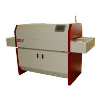
SEF 551.19 Operating Manual (238 pages)
Brand:
SEF
| Category:
Soldering Gun
| Size: 9 MB
Table of Contents
Table of Contents
3
1.0 Preface
11
Safety Signs
14
2.0 Safety Instructions
14
General Instructions
15
Safety Notes
15
Used Norms
16
Intended Use
17
Remaining Risks
17
Responsibility of Operator and Operating Staff
18
Owner
18
Operator
18
Authorised Service Staff
18
Responsibility of Operator and Operating Staff
19
Legal Safety Requirements
19
Personal Safety
19
Reference to Other Suppliers
19
Spare Parts
19
Safety Notes for Installation and Initial Start-Up
21
Connection Conditions
21
Location
21
Exhaustion
21
Safety Notes for Daily Start of Operation and Automatic Operation
23
Safety at the Working Place
23
Solder Paste and Chip Adhesive
23
Protective Equipment
23
Failures
25
Optical Signals
25
Safety Notes for Maintenance and Service
26
Five Safety Rules
26
Dismounting of Safety Devices
27
Disposal Notes
28
3.0 Warranty
29
Rights of Use
30
Assignment of the Rights of Use
30
Liability
30
Reshipment
30
Special Restrictions
31
Caveat Emptor
31
4.0 Technical Data
34
Dimensions of the Soldering System 551.10 / 551.15
34
Dimensions
35
Electrical Connection Values
35
Allowed Climatic Demands
35
Allowed Component Sizes
35
Characteristics
35
Emissions
35
4.0 Technical Data
35
Dimensions of the Soldering System 551.10 / 551.15 with Power Supply 220V Triangle Circuit
36
4.0 Technical Data
36
Option Power Supply 220V in Triangle Circuit
37
Dimensions
37
Electrical Connection Values
37
4.0 Technical Data
37
Dimensions
39
Electrical Connection Values
39
Allowed Climatic Demands
39
Allowed Component Sizes
39
Characteristics
39
Emissions
39
Functional Scheme 551.10 - 4 Heating Zones
40
Functional Scheme
41
Heating Chamber
41
Cooling Zone, Exhaust Hood
41
Transport
41
Operating Panel 7'' Touch Screen
43
Controller (SBCC-Board)
43
Central Electrics 551.10 / 551.15
46
Central Electrics 551.19
46
Central Electrics
47
Controller RO-R2R
48
Component Sizes Pin Chain Conveyor
53
Parameters Pin Chain Conveyor
53
Base Cabinet 551.10.1
55
Option Exhaust Box 551.10.2
57
5.0 Transport and Setting up
59
Transport Notes
60
Safety Instructions for Mounting and Dismounting
61
Liability
61
Unpacking
63
Checking Scope of Delivery
63
Transport on Pallet
63
System 551.10 / 551.15 Setup and Alignment
65
Working Table
65
System 551.19 Setup and Alignment
67
Align Soldering System Horizontally
68
Mains Supply
68
Name Plate 400VAC/N/PE
68
Power Supply 400VAC/N/PE
68
Name Plate 220VAC D
68
Power Supply 220VAC D
68
Name Plate 220VAC D
69
Power Supply 220VAC D
69
Exhaust Connection
71
Interfaces
72
Main Switch
72
Operating Switch On/Off
72
Profile Setting
72
Final Check
73
Dismounting, Storage and Preservation
74
Dismounting
74
Short-Term Out-Of-Operation
74
Functional Description
77
Heating Chamber
77
Thermocouples
77
Cooling Zone
77
Exhaustion
77
Mesh Belt
79
Operating the System
79
Machine Status
79
Emergency-Stop
81
Safety Circuit
81
The Operating Panel
83
Touch Screen Controller Based on SBCC
83
Turn the Soldering System On/Off
85
Main Switch
85
Turn Soldering System on
85
The System Screen
85
Basic Structure of Screen
86
System Display
87
Operating Modes of Soldering Systems Series
87
Menu Structure Load Program
88
Load Program
89
Select Program
89
Menu Structure Edit Program
90
Edit Program
91
Menu Structure Save Program
92
Save Program
92
Save Program
93
Profile Measurement
97
Menu Structure Setup
100
Setup
101
Parameter Adjustment
105
Preheating Time
105
Time above Liquidus
107
Cooling Time
107
Example Component Thickness 1,6 MM - 2,5 MM(Small Components)
108
Example Component Thickness > 2,5 MM (Small Components)
108
Peaktemperature
109
Ramp-Up / Ramp-Down Gradient
109
Load Program
112
Select Program
113
Load Program
113
Edit Program
115
Adjust Nominal Temperature
115
Adjust Conveyor Speed
117
Save Program
119
Overwrite Program
120
Save Program
121
Option Pin Chain Conveyor
123
Adjust Working Width of Pin Chain Conveyor
123
7.0 Soldering Profile Management and Production
123
Start Production
124
Start System
124
Heat-Up Phase
124
Fill the Oven
126
Start Soldering or Curing Process
126
Cooling down Phase 551.10
127
Cooling down Phase 551.19
127
Cooling down Phase 551.15
127
Finish Process
127
Profile Measurement
129
Start Measurement
129
Stop Measurement
130
Stop or Change Production
131
Change Production
131
Stop Production
131
Switch System off
132
Language Selection
135
Set Language
135
Colour Scheme
136
Select Colour Scheme
137
Temperature Display
139
Select Temperature Display
139
Activate Password Protection for Programs
141
Activate Password Protection
141
Standby Parameters
143
Power Save Package
143
Set Standby Time
143
Set Standby Temperature
143
Install Update
145
Software-Update
145
General Safety Instructions
150
9.0 Maintenance and Service
150
Safety Instructions for Opening and Closing the Hood
151
Set System out of Operation
151
Opening the Hood
152
Closing the Hood
153
Cleaning and Maintenance Intervals
154
Cleaning
154
Maintenance
154
Lubrication
155
Cleaning Work
157
Cleaning Work at the Outer Machine Body
157
Cleaning of the Blowers
159
Cleaning of the Fans
161
Cleaning of the Exhaust Hood "Inlet
163
Cleaning of Heating Module
164
Cleaning of Cooling Module
164
Cleaning of the Exhaust Hood "Outlet
165
Cleaning of the Guiding Rails
167
Cleaning of the Mesh Belt
167
Error Diagnosis
168
Check and Exchange Fuses
170
Exchange Damaged Fuse
171
Exchange Damaged Fuse
173
Option Power Supply 220V in Triangle Circuit
174
Mounting Plate Inlet
175
Mounting Plate Outlet
175
Exchange Blower
176
Exchange Fan
178
Dismount Fan
179
Exchange Heating Elements of the Upper Heating Modules
181
Dismount Heating Module
181
Exchange Upper Heating Element
184
Mount Upper Heating Module
185
Exchange Heating Elements of Lower Heating Zones
187
Dismount Lower Heating Element
187
Mount Lower Heating Element
188
Exchange Temperature Sensors in the Upper Heating Modules
191
Dismount Upper Heating Module
192
Exchange Upper Temperature Sensor
194
Mount Upper Heating Module
194
Exchange Temperature Sensor in Lower Heating Zone
197
Exchange Lower Temperature Sensor
198
Dismount Operating Panel
200
Exchange Operating Panel
201
Mount Operating Panel
201
Dismount Controller RO-R2R
202
Exchange Controller Board RO-R2R
203
Exchange Motor / Drive Belt
205
Dismount Motor
205
Dismount Drive Belt
206
Tension Drive Belt
207
Hardware for the Network Connection
210
11.0 Options and Spare Parts
210
Option Communication Package
211
Network Setup
216
Network Configuration
216
Option Communication Package - Network Setup
217
Create Directories
218
Server Computer - Directories
218
Soldering System Software RO-R2 - Settings
218
Server Software Setup
220
Port Setup
221
Set Admin Interface
221
Create User
222
Assign Directory
223
Set up External Operation
226
Option Communication Package - External Operation
227
Configure VNC
227
Operating Mode of the Soldering System Series
229
Thermocouples
231
12.0 Notes
233
Advertisement
Advertisement
Related Products
SEF 548.04
SEF 548.10
SEF 551.10
SEF 551.15
SEF 570.77A
SEF 570.70
SEF Categories
Soldering Gun
Measuring Instruments
Cookers
Data Loggers
More SEF Manuals
Login
Sign In
OR
Sign in with Facebook
Sign in with Google
Upload manual
Upload from disk
Upload from URL