Sign In
Upload
Manuals
Brands
SEF Manuals
Soldering Gun
548.10
SEF 548.10 Manuals
Manuals and User Guides for SEF 548.10. We have
1
SEF 548.10 manual available for free PDF download: Operating Manual
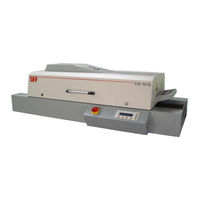
SEF 548.10 Operating Manual (135 pages)
IR-Force-Convection-Soldering-System
Brand:
SEF
| Category:
Soldering Gun
| Size: 3 MB
Table of Contents
1 Preface 2
3
Table of Contents
3
1 0 Preface
13
Introduction
14
Proper Use
15
Utilization Rights
16
Protection of the Product
16
Subject of the Agreement
16
Warranty
16
Warranty Claim Processing
16
Assignment of Utilization Rights
17
General Provisions
17
Liability
17
Particular Restrictions
17
Product Modifi Cations or Improvements
17
Informations about this Operating Manual
18
Important Symbols Contained in the Operating Manual
20
Technical Data
21
Emmissions
21
Sound Compression
21
2 0 Safety Instructions
22
General
23
Important Symbols Contained in the Operation Manual
24
Mandatory Sign
24
Prohibition Sign
24
Text Symbols
24
Warning Sign
24
Defi Nitions
25
Operators
25
Protective Clothing
25
Remaining Risks
25
Accident Prevention Rules
26
Operation of System
27
General Safety Instructions
27
Operator Position
28
Symbols at the System
29
General
29
Warning Sign for Accident Hazard
29
Warning Sign for Danger of Burns
29
Warning Sign for High Voltage
29
Mounting, Dismounting, and Maintenance
30
You Should Know and Observe the Following
31
Emergency Shut-Off
31
Danger of Burns
31
Accident Hazard
31
EMC Instructions
31
Hazardous Soldering Vapors
31
Instructions from Other Suppliers
31
Acoustically Indications
31
Disposal Instructions
32
General Remarks
32
3 0 Quick Reference Guide
33
Installation
34
Aligning
34
Electrical Connection
34
Erecting
34
Unpacking
34
Exhaust Air Connection
35
Interface
36
Mains Switch
36
Final Checkup
37
Turn the System on and off
38
The System Screen
38
Turn the System on
38
Enter New Process Parameters
39
Create a Soldering or Gluing Profi le
39
Enter the Speed
39
Enter the Temperature Value
39
Enter Blower Value
40
Save a Program
41
Delete a Program
42
Load a Program
42
Program Printout
43
Recording a Process Curve
44
Mount the Sensor
44
Analyze a Process Curve
45
Load a Process Curve
45
Save a Process Curve
46
Print a Process Curve
47
System Settings
48
Select Contrast
48
Select Language
48
Immediate Printout
49
Interval Printing
49
Protocol Printout
49
Select Printer Type
50
Set Date and Time
51
4 Prior to Operations
52
Transportation
53
Transportation Instructions at the Packaging
53
Unpacking and Controlling the Parts of Delivery
54
Checking Parts of Delivery
54
Parts of Delivery
54
Unpacking the System
54
What to Do in Case of Damage
54
Connecting the System
55
Dimensions of Thesoldering-System
56
Scale the System to a Horizontally Level
57
Electrical Connection
58
Connections at the System
58
Exhaust Air Connection
58
Interface
59
Mains Switch
59
PC Interface
59
Printer Interface
59
Final Checkup
60
Dismounting the System
61
Electrical Connection
61
Exhaust Air Connection
61
5.0 Operation of System
63
Technical Description
64
Function Keys
65
LCD Display
65
Main Switch
65
Operating Panel
65
The Elements for Operating
65
The Operating Panel
65
Menu Structure
66
Measurement Screen
67
Parameter Screen
67
Program Screen
67
The System Screen
68
Turn the System
68
Turn the System on and off
68
Heating Process
69
Information of the System Screen
69
On and off
69
Open the Cover
69
Create a Soldering or Glueing Profi
70
Parameter Setting
70
Enter the Values
71
Enter Blower Value
72
Enter the Speed
73
Parameter Printout
74
Save a Program
75
Identifi Cation
76
Overwrite a Program
76
Select a Place
76
Program Printout
79
6.0 Production
80
Program Selection
82
Process Documentation
83
Close Covers
85
Open Covers
85
The Circuit Board Remained Inside the System
85
7.0 Measurement
86
Recording a Process Curve
87
Record a Process Curve
88
Load a Process Curve
89
Analyze a Process Curve
90
Curve
91
Save a Process
91
Identifi Cation
92
Overwrite a Process Curve
92
Select a Place
92
Print a Process Curve
93
8.0 System Settings
94
Language Selection
95
Immediate Printout
96
Protocol Printout
96
Select Contrast
98
Select Printer Type
99
Set Date and Time
100
System Service
101
9.0 Maintenance
102
Cleaning Intervals
103
Relieved Cleaning Work
104
Plan of Diagnosis
106
The Electronic of the Soldering System
108
Change the Temperature Sensor on a Radiator
111
Change Thetemperature Sensor in the Heating Chamber
115
Change the Blower
116
Dismounting and Mounting the Grid Belt Transport
118
Change the Power Unit
119
Dismounting and Mounting of the Transport Control
120
Dismounting and Mounting of the Mains Fi Lter
121
Change the Power Supply
122
Software Update
124
10.0 Technical Appendix
127
Pin Configuration Parallel Interface
127
Over View of the Electronic
128
Thermo Measuring Modul 236.02 A0
128
Operating Panel 236.01 B1
128
Power Unit 271-02 A9
129
Power Board 238-01 A1
131
Advertisement
Advertisement
Related Products
SEF 548.04
SEF 551.10
SEF 551.15
SEF 551.19
SEF 570.77A
SEF 570.70
SEF Categories
Soldering Gun
Measuring Instruments
Cookers
Data Loggers
More SEF Manuals
Login
Sign In
OR
Sign in with Facebook
Sign in with Google
Upload manual
Upload from disk
Upload from URL