Sign In
Upload
Manuals
Brands
Schweitzer Engineering Manuals
Computer Hardware
SEL-2032
Schweitzer Engineering SEL-2032 Manuals
Manuals and User Guides for Schweitzer Engineering SEL-2032. We have
1
Schweitzer Engineering SEL-2032 manual available for free PDF download: Instruction Manual
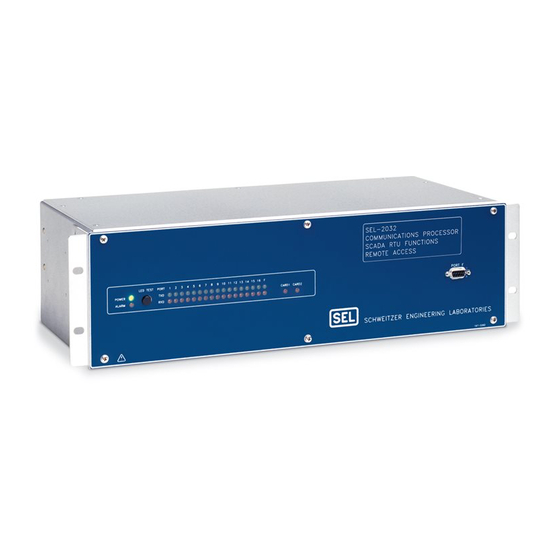
Schweitzer Engineering SEL-2032 Instruction Manual (354 pages)
Communications Processor
Brand:
Schweitzer Engineering
| Category:
Computer Hardware
| Size: 2 MB
Table of Contents
Table of Contents
3
List of Tables
7
Preface
13
Manual Overview
13
Factory Assistance
16
Typographic Conventions
16
Section 1: Introduction and Specifications
17
Introduction
17
Applications
17
Substation Integration
18
Figure 1.1 Typical Integrated Substation System
19
Figure 1.2 Traditional SCADA System
20
Figure 1.3 Ieds Communicating with RTU
20
Integration with the SEL-2032
21
Figure 1.4 Integrated Substation Without a Communications Processor
22
Figure 1.5 System Integrated Using the SEL-2032 Communications Processor
22
Integration Process
25
Figure 1.6 Multitiered SEL-2032 System
25
Network Interfaces
28
Functions
29
Table 1.1 Communications Type
30
Figure 1.7 SEL-2032 Manages Communications with Multiple Master and Slave Devices
30
Figure 1.8 SEL-2032 Database Structure
33
Figure 1.9 User Region/Set M Setting Operation
35
Figure 1.10 Transparent Connection Provides Direct Access to Many Ieds through a Single Connection Point (Modem)
39
Figure 1.11 SEL-2032 Distributes Time Synchronization Using IRIG-B over Star Data and Control Network Connections
40
Details
41
Table 1.2 Differences between the SEL-2030 and SEL-2032
43
Specifications
44
Section 2: Installation
47
Introduction
47
Jumper Settings
47
Table 2.1 Main Board Jumper Positions
47
Main Board
47
Table 2.2 Optional I/O Board Contact Form Jumper Positions
48
Mounting and Connections
49
Power Connections
50
Figure 2.1 9-Pin Connector Pin Number Convention
51
Table 2.3 Serial Port Connector Pin Definitions
52
Table 2.4 Communication Cables for Devices Attached to SEL-2032
52
Communications
54
Figure 2.2 Cable C234A Pinout Configuration
54
Drawings
57
Figure 2.3 SEL-2032 Front and Rear Panels
57
Figure 2.4 SEL-2032 Main Board Jumper Location
58
Figure 2.5 SEL-2032 Optional I/O Board Jumper Location
59
Figure 2.6 SEL-2032 Dimensions and Panel-Mount Cutout
60
Getting Started
61
Figure 2.7 ACCESS Command Screen
61
Figure 2.8 STATUS Command Screen
62
Figure 2.9 AUTO 2 Command Displays Fast Message Features
64
Figure 2.10 Issue the WHO Command to Verify Relay Port Connection
65
Figure 2.11 MAP 2 Command Verifies Data Types and Locations
66
Figure 2.12 MAP 2:METER Command Verifies Metering Quantities
67
Figure 2.13 MAP 2:TARGET Command Displays TARGET Region Data
68
Figure 2.14 STATUS Command Checks Communication and Data Retrieval
69
Section 3: Job Done Examples
71
Introduction
71
Example 1: Connect to the Front Port and Change Default Passwords
71
Table 3.1 Factory-Default Passwords for Access Levels 1, 2, and C
72
Figure 3.1 Commands Available
72
Figure 3.2 Changing Access Levels
73
Figure 3.3 Using the PAS Command
73
Example 2: Using the SEL-2032 as a Port Switch
74
Figure 3.4 SEL-2032 Configured with SEL-251 Relays, External Modem, and IRIG-B Source
74
Table 3.2 Example 2 Front Port Settings (SET P)
76
Table 3.3 Example 2 Relay Port Settings (SET P)
76
Figure 3.5 Global Data Region Contents
77
Table 3.4 Example 2 Port 1 Automatic Messaging Settings
78
Table 3.5 Example 2 Modem Port Settings
79
Figure 3.6 Settings COPY Command Example
79
Figure 3.7 STATUS Command Example
80
Figure 3.8 Initiate Transparent Communications
81
Figure 3.9 Relay Group 1 Settings
82
Figure 3.10 Terminate Transparent Communications
82
Figure 3.11 TOGGLE Command Example
82
Example 3: Collect SEL Relay Status and Measurements
83
Figure 3.12 Example AUTO Command Output
84
Figure 3.13 WHO Command Example
85
Figure 3.14 MAP Command Example
86
Figure 3.15 MAP 2:METER Command Example
87
Figure 3.16 Example MAP Command on the TARGET Region
88
Figure 3.17 STATUS Command Example
88
Example 4: Collect Unsolicited Write (Synchrophasor) Data
89
Table 3.6 SEL-311C Global Settings for Synchrophasors
89
Table 3.7 SEL-311C Serial Port Settings for Synchrophasors
90
Figure 3.18 Example AUTO Command Output
91
Figure 3.19 Example SET a 3 Settings
91
Figure 3.20 View 3:USER Output
92
Figure 3.21 Math/Move Equations and 17:USER Contents
92
Example 5: Getting Data from a Non-SEL IED
93
Table 3.8 SEL-2032 DNP LAN/WAN Settings
93
Figure 3.22 Non-SEL IED Attached to Port 12
94
Table 3.9 Example 5 Port 12 Settings
95
Table 3.10 Example 5 Port 12 Automatic Message Settings
95
Example 6: Modbus Job Done
96
Table 3.11 Example 6 Port 16 Port Configuration Settings
96
Figure 3.23 TOGGLE Command Asserts the D1 Bit on Port 12
96
Figure 3.24 Received Message
98
Figure 3.25 Response Message
98
Table 3.13 Example 6 Port 16 Math/Data Movement Settings
100
Figure 3.26 Port 3 Meter Region Data Map
100
Figure 3.27 Port 4 Meter Region Data Map
100
Figure 3.28 Received Message
101
Figure 3.29 Response Message
102
Figure 3.30 Received Message
103
Figure 3.31 Response Message
103
Section 4: SEL OGIC Control Equations
105
Introduction
105
Operation
105
Inputs
106
Equation Syntax
108
Outputs
109
Figure 4.2 Example of Latch Operation
109
Figure 4.3 Message Triggering Logic
110
Figure 4.4 Normal Auto-Message Trigger
110
Figure 4.5 Unsuccessful Auto-Message Trigger
111
Figure 4.6 Trigger Lock-Out Problem
111
Figure 4.7 Forcing Retriggering Avoids Trigger Lock-Out
112
Figure 4.8 Processing Sequence Illustration
113
Communications and Triggered Messages
114
Section 5: Message Strings
115
Introduction
115
Overview
115
Literal Characters
115
Special Sequences
116
Table 5.1 Special Characters for Use in Strings
116
Table 5.2 Special Message Sequences for Strings
116
Predefined Strings
120
Table 5.3 Special Parsing Sequences for Strings
120
20EVENT Features
121
Table 5.4 Predefined Strings for Auto-Messages with Auto-Configured SEL Ieds
121
Table 5.5 Other Predefined Strings for Auto-Messages
121
Table 5.6 Predefined Strings for General-Purpose User-Defined Commands
121
Modem Dial-Out Process
122
Section 6: Database
125
Introduction
125
Database Structure
125
Table 6.1 Database Regions for a Single Port
126
Figure 6.1 Overall Database Structure
126
Region Descriptions
128
Table 6.2 Global Region
128
Figure 6.2 Register Usage for Different Data Types
128
Figure 6.3 Global Status Register
131
Figure 6.4 Configuration Register
131
Figure 6.5 Remote Bit Control Register
132
Figure 6.6 Port F Status Register
132
Table 6.3 Global Elements
133
Table 6.4 Global Element Definitions
134
Table 6.5 Local Region
135
Figure 6.7 Port Status Register
138
Table 6.6 Local Elements
139
Table 6.7 Local Element Definitions
141
Table 6.8 Ports 17 and 18 Control Input and Output Elements
142
Table 6.9 BUF (Unsolicited Message Queue) Organization
143
Access Methods
146
Table 6.10 Data Access by Region Labels
146
Section 7: Settings
149
Introduction
149
SET Commands
149
Port Configuration (SET P) and Communication Settings
150
Figure 7.1 SET Commands as They Apply to SEL-2032 Ports
150
Table 7.1 Port Configuration (SET P) Settings Information
151
Figure 7.2 EIA-232 Character Format
155
Automatic Message (SET A) Settings
159
Figure 7.3 Automatic Message Operation Functional Block Diagram
160
Table 7.2 SEL-2032 Minimum Data Collection Period (in Seconds)
161
Table 7.3 Decode Element Definitions
165
Table 7.4 Data Type Characteristics
165
Figure 7.4 SEL-351R Min/Max Report
168
Table 7.5 Example Position Settings
169
Table 7.6 Automatic Message (SET A) Settings Information
171
User-Defined (SET U) Commands
175
Figure 7.5 SET U Example CMD1 Message Detection
176
Table 7.7 User-Defined (SET U) Settings
178
Logic (SET L) Settings
179
Math/Data Movement (SET M) Settings
179
Table 7.8 Logic (SET L) Settings
179
Table 7.9 Editing Keys and Commands for SET M and SET R
179
Table 7.10 Math/Data Movement Equation Parameters
180
Figure 7.6 Example VIEW Command
182
Figure 7.7 Example Math/Data Movement Settings
182
Figure 7.8 Character String Parsed Data
182
Data Type
183
Figure 7.9 Data Conversion Settings
183
Flow Control
183
Global (SET G) Settings
184
Table 7.11 Global (SET G) Settings and Definitions
185
SER (SET R) Settings
186
Logic (SET O) Settings
187
Settings Sheets
187
Table 7.12 Logic (SET O) Settings and Definition
187
Section 8: Serial Port
217
Communications and Commands
217
Introduction
217
Command Operation
217
Table 8.1 Access Level Characteristics
218
Figure 8.1 Noninteractive Message Format
218
Command Set
219
Figure 8.2 2ACCESS Command
220
Figure 8.3 ACCESS Command
220
Figure 8.4 Access Denied Message
220
Figure 8.5 AUTO Command
221
Figure 8.6 CAL Command
221
Figure 8.7 CARD Command
222
Figure 8.8 CONTROL Command
222
Figure 8.9 COPY Command
223
Figure 8.10 DATE Command
224
Figure 8.11 DCF Command
224
Figure 8.12 DCF Command with NOECHO Parameter
224
Figure 8.13 DEFRAGMENT Command
224
Figure 8.14 DNPMAP Command
225
Table 8.2 Variations on the FILE Command
226
Figure 8.15 HELP Command
226
Figure 8.16 ID Command
227
Figure 8.17 ID Command for Installed Protocol Cards
227
Figure 8.19 Port MAP Command
228
Figure 8.20 Data Region MAP Command
229
Figure 8.21 MAP Command with BL Option
229
Figure 8.22 MEM Command
230
Figure 8.23 MODMAP Command
231
Figure 8.24 PASSWORD Command Password Display
231
Figure 8.25 PASSWORD Change Sequence
232
Figure 8.26 PORT Command
233
Table 8.3 Variations of the SER Command
234
Figure 8.27 SER Command
234
Table 8.4 Examples of Variations on the SET Command
235
Figure 8.28 SER Command with BL Option
235
Table 8.5 Editing Keys for SET Commands
236
Figure 8.29 Active State for (Overrun)
237
Table 8.6 Status Report Description
238
Figure 8.30 Active State for (Data)
238
Figure 8.31 STORE Command
240
Figure 8.32 SWAP Command
241
Figure 8.33 TIME Command
241
Table 8.7 VIEW Command Parameters
242
Figure 8.34 WHO Command
243
Section 9: Protocols
245
Introduction
245
SEL Fast Message Protocol
245
Figure 9.1 Example AUTO Command Operation
246
Table 9.1 SEL-2032 Serial Port Bandwidth for Synchrophasors (in Bytes)
249
Modbus RTU Protocol
252
Figure 9.2 SEL-2032 Multitiered Application Example
252
Table 9.2 Modbus Data Types
253
Figure 9.3 SEL-2032 Virtual Modbus Network
253
Table 9.3 SEL Modbus Map Summary
254
Table 9.4 Supported Function Codes
257
Table 9.5 Supported Bit Addresses
258
Table 9.6 Control Point Addresses
258
Table 9.7 Device
263
Error Handling
264
Table 9.8 Example Register Map for Meter Data, Integer Type
265
Table 9.9 Example Map for Demand Meter Data, Integer Type
268
Table 9.10 Example Register Map for History Data, Integer Type
269
Table 9.11 Example Register Map for Relay Target Data, both Types
269
Table 9.12 Target Data
270
Table 9.13 Register Map for Breaker Data, Integer Type
270
Serial Distributed Network Protocol (Serial DNP3)
271
Table 9.14 Example Register Map for User Data
271
Table 9.15 Data Access Methods
272
Table 9.16 SEL-2032 DNP3 Device Profile
273
Table 9.17 SEL-2032 DNP3 Object List
274
Table 9.18 Binary Object Operations (DNP_PAIR
279
Table 9.19 Relative Indices
280
Table 9.20 Binary Output Objects (DNP_PAIR
280
Table 9.21 Settings Enabled When DNP_PAIR
281
Table 9.22 Example Control Points
282
Table 9.23 Example Control Points
282
Figure 9.4 SER Data Flow
284
Figure 9.5 Example AUTO Command Response for Device that Supports Fast SER
285
Table 9.24 Two-Tier Fast SER Math/Movement Statement Parameters
286
Distributed Network Protocol 3.0 (DNP3) LAN/WAN
287
Table 9.25 SEL-2032 Ethernet Port DNP3 Protocol Settings
288
Table 9.26 DNP3 over Ethernet Access Methods
290
Table 9.27 SEL-2032 DNP3 over Ethernet Device Profile
291
Table 9.28 SEL-2032 DNP3 LAN/WAN Object List
292
Table 9.29 SEL-2032 DNP3 over Ethernet Object 12 Control Point Operation
298
Figure 9.6 SEL-5020: Set DNP Map Mode to CUSTOM
301
Figure 9.7 SEL-5020: Assign Custom DNP3 Map to Master
301
Table 9.31 SEL-2032 DNP3 over Ethernet Map Settings
302
Figure 9.8 SEL-5020: Sample Custom Binary Input DNP3 Map
304
Figure 9.9 SEL-5020: Sample Custom Analog Input DNP3 Map
304
Table 9.32 SEL-2032 DNP3 LAN/WAN Object 12 Control Point, DNPMAP = CUSTOM
305
Figure 9.10 SEL-5020: Sample Binary Output Custom DNP3 Map
306
Figure 9.11 SEL-5020: Sample Analog Output Custom DNP3 Map
306
Figure 9.12 Sample Set_Dnp1.Txt File
307
LMD Distributed Port Switch Protocol
309
Section 10: Testing and Troubleshooting
311
Introduction
311
Alarm Conditions
311
Table 10.1 Alarm Conditions
311
Self-Tests
312
Troubleshooting
312
Table 10.2 Power System Problems
312
Table 10.3 Communications Problems
312
Initial Checkout
314
Figure 10.1 ACCESS Command Screen
314
Calibration
315
Battery Replacement
315
Figure 10.2 STATUS Command Screen
315
Relay Firmware Upgrades
316
Table A.1 Firmware Revision History-SEL-2032 Instruction Manual
317
Appendix A: Firmware and Manual Versions Firmware
318
Table A.2 Instruction Manual Revision History
319
Appendix B: Firmware Upgrade Instructions
323
Overview
323
Upgrade Procedure
324
Table B.1 Firmware Upgrade Files
324
Table B.2 Firmware Upgrade Command Summary
325
Upgrade Warning
327
Factory Assistance
327
Appendix Csel IED Compatibility
329
Table C.1 SEL-2032 Compatibility Matrix
329
Appendix D System Planning Sheet
331
Figure D.1 SEL-2032 Device Connection Plan
331
Calculate Memory Usage
332
Table D.1 "20" Message Archive Requirements in Blocks
332
Date Code
333
Table D.2 Archive Memory Usage Estimation
334
Table D.3 Data Record Sizes (Bytes) by Relay and Record Type
335
Appendix Eascii Reference Table
337
Glossary
339
Index
341
SEL-2032 Command Summary
343
SEL-2032 Message Strings
345
Advertisement
Advertisement
Related Products
Schweitzer Engineering SEL-300G
Schweitzer Engineering SEL-387-0
Schweitzer Engineering SEL-387-5
Schweitzer Engineering SEL-387-6
Schweitzer Engineering SEL-3355-2
Schweitzer Engineering SEL-351P
Schweitzer Engineering Categories
Controller
Relays
Computer Hardware
Industrial PC
More Schweitzer Engineering Manuals
Login
Sign In
OR
Sign in with Facebook
Sign in with Google
Upload manual
Upload from disk
Upload from URL