Sign In
Upload
Manuals
Brands
Schweitzer Engineering Laboratories Manuals
Relays
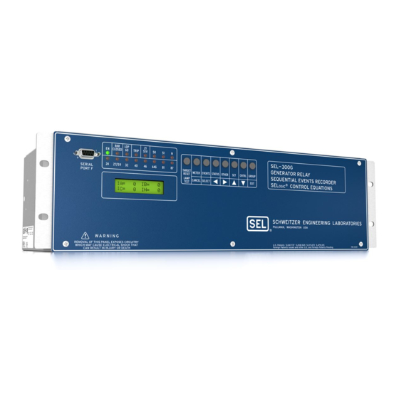
SEL-300G
Schweitzer Engineering Laboratories SEL-300G Manuals
Manuals and User Guides for Schweitzer Engineering Laboratories SEL-300G. We have
3
Schweitzer Engineering Laboratories SEL-300G manuals available for free PDF download: Instruction Manual, Manual
Schweitzer Engineering Laboratories SEL-300G Instruction Manual (714 pages)
MULTIFUNCTION GENERATOR RELAY
Brand:
Schweitzer Engineering Laboratories
| Category:
Relays
| Size: 8 MB
Table of Contents
Table of Contents
9
Section 1: Introduction and Specifications
11
Welcome
11
Table 1.1: SEL-300G Relay Instruction Manual Task Map
11
Typographic Conventions
12
SEL-300G Relay Models
12
Table 1.2: SEL-300G Relay Models
12
Table 1.3: SEL-300G Relay Hardware Models
13
Instruction Manual Sections Overview
14
SEL-300G Relay Protection Applications
16
Complete Generator Primary Protection
16
Figure 1.1: Large Generator Primary and Backup Protection
16
Feature-Rich Generator Backup Protection
17
Figure 1.2: Generator Differential Zone May Include Transformer
17
Figure 1.3: Simple Protection for Resistance Grounded Generators
17
Protection for Small- and Medium-Sized Machines
17
Solidly Grounded Machine Protection
18
Thermal Protection of Generator and Prime Mover
18
SEL-300G Relay Generator Protection Features
18
Figure 1.4: Generator Thermal Protection with SEL-2600 & SEL-300G Relay
18
SEL-300G Relay Additional Features
19
Contact I/O Application
19
Available Contact Input/Output Options
19
Power Supply and Optoisolated Input DC Voltages
20
Serial Communication Connections (Typical)
21
Figure 1.5: SEL-300G Relay Communication Connection Examples
21
SEL-5801 Cable SEL ECTOR Software
22
SEL-300G Relay Ordering
22
Place a Request for Quotation or Order
22
Create a Relay Part Number (Screw-Terminal Block Option)
23
Table 1.4: SEL-300G Relay (Screw-Terminal Block) Part Number Creation Table
23
Create a Relay Part Number (Connectorized Option)
25
Table 1.5: SEL-300G Relay (Connectorized) Part Number Creation Table
25
Communication Cables
26
Special Specifications
26
Relay Specifications and Options
27
General
27
Processing Specifications
29
Relay Element Setting Ranges and Accuracies
29
Section 2: Relay Element Settings
35
Relay Functional Overview
41
Data Acquisition and Filtering
41
Relay Element Settings
41
Element Processing
42
Relay Word
42
SEL OGIC ® Control Equations
42
Background Tasks
42
Section 2: Relay Element Settings
41
Relay Settings Overview
42
Protection Element Selection Guidelines
45
Relay Configuration Settings
46
Group 1, Group 2 Configuration Setting Descriptions
46
Global Configuration Setting Descriptions (SET G)
49
BKR Monitor
51
Display Point Settings
51
Local Bit Settings
51
Optioisolated Input Timers
51
Setting Group Selection
51
Phase Mho Distance Element
51
Element Description
51
Functional Description
51
Setting Descriptions
52
Relay Word Bits
54
Setting Calculation
54
Information Needed
54
Recommendations
54
Phase Distance Tripping
55
Reverse-Power Tripping
68
Element Operating Characteristics
68
Loss-Of-Field Element
69
Element Description
69
Functional Description
69
Setting Descriptions
70
Relay Word Bits
71
Setting Calculation
72
Information Needed
72
Loss-Of-Field Protection Using a Negative Offset Zone 2
72
Recommendations
72
Element Operating Characteristics
74
Negative-Sequence Overcurrent Elements
75
Element Description
75
Functional Description
75
Setting Descriptions
75
Relay Word Bits
76
Setting Calculation
77
Information Needed
77
Negative-Sequence Overcurrent Tripping
77
Recommendations
77
Element Operating Characteristics
78
Overcurrent Elements
80
Element Description
80
Functional Description
80
Overcurrent Protection, All Relay Models
80
Overcurrent Protection, Relay Models with Differential Protection
80
Definite-Time Overcurrent Settings
81
Setting Descriptions
81
Definite-Time 50/87 Overcurrent Settings
82
Neutral Time-Overcurrent Settings
82
Relay Word Bits
83
Residual Time-Overcurrent Settings
83
Neutral Overcurrent Setting Calculation
85
Information Needed
85
Recommendations
85
Neutral Overcurrent Tripping
86
Other Overcurrent Elements
86
Element Operating Characteristics
86
Pickup and Reset Time Curves
86
Element Description
94
Functional Description
94
Setting Descriptions
95
Relay Word Bits
96
Voltage-Controlled and Voltage-Restrained Time-Overcurrent Setting Calculation
96
Information Needed
96
Recommendations
96
Voltage-Controlled Time-Overcurrent Settings
96
Voltage-Restrained Time-Overcurrent Settings
97
Overcurrent Tripping
98
Element Operating Characteristics
98
Over/Under Voltage Elements
100
Element Description
100
Functional Description
100
Setting Descriptions
100
Voltage Element Setting Calculation
101
100% Stator Ground Protection Elements
104
Setting Descriptions
106
Relay Word Bits
107
100% Stator Ground Protection Setting Calculation
107
Information Needed
107
Third-Harmonic Voltage Differential Setting Recommendations (Four-Wire Potentials Required)
107
Third-Harmonic Neutral Undervoltage Setting Recommendations (Use with Open-Delta Potentials)
109
100% Stator Ground Fault Tripping
111
Element Operating Characteristics
111
Element Description
112
Functional Description
112
Setting Descriptions
115
Relay Word Bits
116
Settings Calculation
116
Information Needed
116
Recommendations
116
Element Description
118
Functional Description
118
Relay Word Bits
122
Settings Calculation
122
Information Needed
122
Recommendations
122
Loss-Of-Potential (60LOP) Protection
104
Element Description
104
Functional Description
104
Relay Word Bits
104
Setting Descriptions
104
Frequency Protection
125
Element Description
125
Relay Word Bits
126
Frequency Element Setting Calculation
126
Information Needed
126
Recommendations
126
Underfrequency Tripping
127
Element Operating Characteristics
127
Off-Frequency Accumulators
129
Element Description
129
Functional Description
129
Setting Descriptions
129
Relay Word Bits
130
Abnormal Frequency Protection Setting Calculation
131
Abnormal Frequency Tripping
131
Information Needed
131
Recommendations
131
Element Operating Characteristics
132
RTD-Based Protection (Models Compatible with SEL-2600 RTD Module)
134
Element Description
134
Functional Description
134
RTD Configuration Settings
134
RTD Location Settings
134
Setting Descriptions
134
RTD Type Settings
135
RTD Alarms & Trip Temperature Settings
136
Relay Word Bits
140
Pole Open Logic
141
Element Description
141
Functional Description
141
Relay Word Bits
141
Setting Descriptions
141
Pole Open Logic Setting Calculation
142
Recommendations
142
Breaker Failure Protection
142
Differential Protection
142
Inadvertent Energization Protection
142
Synchronism Checking
142
Section 3: Auxiliary Function Settings
143
Demand Meter
145
Functional Description
145
Comparison of Thermal and Rolling Demand Meters
145
Demand Ammeter Thresholds
149
Setting Descriptions
149
Relay Word Bits
150
Introduction
145
Section 3: Auxiliary Function Settings
145
Station DC Monitor
152
Element Description
152
Functional Description
152
Setting Descriptions
152
DCLO < DCHI (Top of Figure 3.5)
154
DCLO > DCHI (Bottom of Figure 3.5)
155
Output Contact Type Considerations ("A" or "B")
155
Setting Group Selection Function
156
Active Setting Group Indication
156
Selecting the Active Setting Group
156
Operation of SEL OGIC Control Equation Settings SS1 and SS2
156
Operation of Serial Port GROUP Command and Front-Panel GROUP Pushbutton
157
Active Setting Group Switching Example
157
Feedback Control
159
Active Setting Group Retained
162
Power Loss
162
Settings Change
162
Breaker Monitor Function
163
Breaker Monitor Setting Example
165
Breaker Maintenance Curve Details
165
Bkmon
167
Operation of SEL OGIC Control Equation Breaker Monitor Initiation Setting
167
Optoisolated Input Debounce Timers
168
Input Debounce Timers
169
Input Functions
170
Factory Settings Example
170
Input IN101
170
SER Trigger Settings and Alias Settings
171
SER Triggering
171
Making SER Trigger Settings
171
Alias Settings
172
Table of Contents
173
Introduction
177
Relay Word Bits
177
Relay Word Bit Operation Example - Neutral Time-Overcurrent Element 51NT
178
Neutral Time-Overcurrent Element 51NT Pickup Indication
178
Neutral Time-Overcurrent Element 51NT Reset Indication
178
Neutral Time-Overcurrent Element 51NT Time out Indication
178
Relay Word Bit Application Examples - Neutral Time-Overcurrent Element 51NT
179
Other Relay Word Bits
179
SEL OGIC Control Equation Overview
177
Sel Ogic ® Control Equations
177
SEL OGIC Control Equations
179
SEL OGIC Control Equation Operators
180
SEL OGIC Control Equation Falling Edge Operator
180
SEL OGIC Control Equation Rising Edge Operator
180
Example of NOT Operator, !, Applied to Single Element
181
SEL OGIC Control Equation NOT Operator
181
SEL OGIC Control Equation Parentheses Operator, ( )
181
Example of NOT Operator, !, Applied to Multiple Elements (Within Parentheses)
182
All SEL OGIC Control Equations Must be Set
183
Set SEL OGIC Control Equations Directly to 1 or 0
183
SEL OGIC Control Equation Limitations
183
Nondedicated SEL OGIC Control Equation Variable Settings
184
Latch Control Switch Application Ideas
186
Local/Remote Generator Shutdown Setting Example
186
Use Local Bit LB1 or Remote Bit RB1 to Shut down the Generator
187
Latch Control Switch States Retained
187
Power Loss
187
Settings Change or Active Setting Group Change
187
NOTE: Make Latch Control Switch Settings with Care
187
Unlatch Trip
190
Generator Tripping
190
Generator Main Circuit Breaker Trip, TR1
190
Generator Field Breaker Trip, TR2
191
Prime Mover Trip, TR3
192
Generator Lockout Relay Trip, TR4
193
Factory Default Tripping Logic
194
Generator Abnormal Operating Conditions and Manual Trips
194
Generator Fault, Prolonged System Fault, and Inadvertent Energization
194
Generator Field Circuit Breaker Tripping Settings
195
Generator Main Circuit Breaker Tripping Settings
195
Generator Lockout Relay Tripping Settings
196
Prime Mover Tripping Settings
196
Program Output Contacts for Tripping
197
Close Logic
197
Set Close
198
Unlatch Close
198
Settings Example
199
Set Close
199
Unlatch Close
199
Defeat the Close Logic
200
Program an Output Contact for Closing
200
Synchronism Checking Function (Models 0300G2 and 0300G3)
200
Element Description
200
Functional Description
200
Setting Descriptions
201
Relay Word Bits
203
Setting Calculation
203
Information Needed
203
Recommendations
204
Manually Refine the 25RCF Setting While the Generator Is in Service
207
Synch-Check Supervised Closing
209
Element Operating Characteristics
210
ER Control Equation
212
Output Contact Control
213
Factory Settings Example
213
Operation of Output Contacts for Different Output Contact Types
214
ALARM Output Contact
214
Output Contacts OUT101 through OUT107 (All Models) and OUT201 through OUT212
214
Local Control Switch Types
218
OFF/MOMENTARY Switch
218
ON/OFF Switch
218
ON/OFF/MOMENTARY Switch
219
Factory Settings Examples
220
Additional Local Control Switch Application Ideas
221
Local Control Switch States Retained
221
Power Loss
221
Settings Change or Active Setting Group Change
221
Remote Bit Application Ideas
222
Remote Bit States Not Retained When Power Is Lost
223
Remote Bit States Retained When Settings Changed or Active Setting Group Changed
223
Front-Panel Display Configuration
223
Traditional Indicating Panel Meters
223
Traditional Indicating Panel Meters Replaced with Rotating Meter Display
223
Traditional Indicating Panel Lights
224
Circuit Breaker Status Indication
225
Traditional Indicating Panel Lights Replaced with Rotating Text Display
225
General Operation of Rotating Text Display Settings
226
Factory Settings Examples
226
Circuit Breaker Closed
226
Main Circuit Breaker Status Indication
226
Circuit Breaker Open
227
Additional Settings Examples
227
Circuit Breaker Closed
227
Display Only One Message
227
Continually Display a Message
228
Inadvertent Energization
228
Breaker Failure Protection
232
Application Examples
233
Performance Alarms
233
Circuit Breaker Wear Monitor
234
Generator Off-Frequency Accumulator Protection
234
Loss-Of-Potential, 60LOP
234
Protection Element Alarms
234
Unbalance Current Alarm, 46Q1T and 46Q2
234
Volts/Hertz Overexcitation Alarms, 24D1T and 24C2
234
DC Voltage Monitor
235
Relay Self-Test Alarms
235
Current Transformer Inputs (Connectorized Models)
261
Section 5: Installation
265
Installation
265
Relay Mounting
265
SEL-300G Instruction Manual Date Code
267
Making Rear-Panel Connections
276
Models 0300G_W and 0300G_Y (Connectorized)
276
Required Equipment and General Connect Information
276
Wiring Harness
276
Chassis Ground
279
Models 0300G_0 and 000G_1
279
Models 0300G_0 and 000G_1 (Screw-Terminal Blocks)
279
Models 0300G_0 and 0300G_1
279
Models 0300G_0H, 0300G_03, 0300G_WH, and 0300G_W3
279
Models 0300G_W and 000G_Y
279
Models 0300G_W and 0300G_Y
279
Output Contacts
279
Power Supply
279
High Current Interrupting Output Contacts
280
Models 0300G_1H, 0300G_13, 0300G_YH, and 0300G_Y3
280
Standard Output Contacts
280
Current Transformer Inputs (Connectorized Models)
281
Current Transformer Inputs (Screw-Terminal Block Models)
281
Models 0300G0, 0300G1, 0300G2, and 0300G3
281
Models 0300G1 and 0300G3
281
Optoisolated Inputs
281
Models 0300G1 and 0300G3
282
Potential Transformer Inputs
282
Serial Ports
282
IRIG-B Time-Code Input
283
Example AC and DC Connection Diagrams
284
Accessing the Relay Main Board (All Models) and Extra I/O Board
290
Extra Alarm" Output Contact Control Jumper
293
Password and Breaker Jumpers
294
Condition of Acceptability for North American Product Safety Compliance
295
EIA-232 Serial Port Voltage Jumpers
295
Clock Battery
296
Table of Contents
297
Enter Relay Settings
299
Introduction
299
Settings Changes Via the Serial Port
299
Communication Setup
299
Terminal Emulation
300
Establish Communication
300
Setting Entry
300
Setting Entry Error Messages
301
Volts/Hertz Element
302
Settings Sheets
308
Section 8: Monitoring and Metering Functions
455
Generator Operating Statistics
457
Generator Hour Meters
457
Generator Accumulated I
458
Generator Average Output Power
458
Off-Frequency Operating Time Accumulators
458
Example PROFILE Command Response
458
Resetting the Averages and Accumulators
459
Introduction
457
Section 8: Monitoring and Metering Functions
457
Breaker Monitor
459
Breaker Monitor Operation Example
459
0% to 10% Breaker Wear
459
10% to 25% Breaker Wear
459
25% to 50% Breaker Wear
459
50% to 100% Breaker Wear
460
Breaker Monitor Output
465
Example Applications
465
View or Reset Breaker Monitor Information
465
Via Serial Port
465
Via Front Panel
466
Determination of Relay Initiated Trips and Externally Initiated Trips
466
Factory Default Setting Example
466
Station DC Battery Monitor
466
View Station DC Battery Voltage
467
Via Front Panel
467
Via Serial Port
467
Analyze Station DC Battery Voltage
467
Station DC Battery Voltage Dips During Circuit Breaker Closing
467
Station DC Battery Voltage Dips During Circuit Breaker Tripping
467
Operation of Station DC Battery Monitor When AC Voltage Is Powering the Relay
468
Differential Metering
468
View Differential Metering Information
468
Via Front Panel
468
Via Serial Port
468
Energy Metering
468
View or Reset Energy Metering Information
468
Maximum/Minimum Metering Updating and Storage
470
Section 9: Front-Panel Operation
471
Front-Panel Target Leds
473
Target Reset/Lamp Test Front-Panel Pushbutton
474
Introduction
473
Section 9: Front-Panel Operation
473
Front-Panel Pushbutton Operation
474
Overview
474
Primary Functions
474
Front-Panel Password Security
475
Secondary Functions
476
Local Control Function Description
478
View Local Control (with Factory Settings)
479
Operate Local Control (with Factory Settings)
479
Local Control State Retained When Relay Deenergized
481
Rotating Default Display
481
Table of Contents
483
Section 10: Serial Port Communications and
485
Commands
485
Irig-B
486
SEL-300G to Computer
486
SEL-300G to Modem
487
Communications Protocol
489
Hardware Protocol
489
SEL ASCII Protocol
490
Software Protocols
490
Modbus RTU Protocol
491
SEL Compressed ASCII Protocol
491
SEL Distributed Port Switch Protocol (LMD)
491
SEL Fast Meter Protocol
491
Serial Port Access Levels
492
Access Level 0
492
Access Level 2
492
Access Level B
492
Command Summary
494
Command Explanations
496
ACC, BAC, and 2AC Commands (Go to Access Level 1, B, or 2)
496
Access Level 0 Commands
496
Access Level Attempt (Password Required)
496
HELP Command (Display Available Serial Port Commands)
496
Password Requirements and Default Passwords
496
Access Level 1 Commands
497
Access Level Attempt (Password Not Required)
497
BRE Command (Breaker Monitor Data)
497
DAT Command (View/Change Date)
498
EVE Command (Event Reports)
498
GRO Command (Display Active Setting Group Number)
498
HIS Command (Event Summaries/History)
498
PRO Command (Display Generator Operation Profile)
505
QUI Command (Quit Access Level)
506
STA Command (Relay Self-Test Status)
512
STA Command Row and Column Definitions
512
SYN Command (Synch-Check Function Report) (Models 0300G2 and 0300G3)
512
TAR Command (Display Relay Element Status)
513
Access Level B Commands
516
CLO Command (Close Breaker)
516
GRO N Command (Change Active Setting Group)
516
OPE N Command (Open Breaker)
517
CON Command (Control Remote Bit)
519
COP M N Command (Copy Setting Group)
519
HIS C Command (Clear Event Summaries/History)
520
PAS Command (View/Change Passwords)
520
Pro R
520
SET Command (Change Settings)
521
Sta C
521
SYN R (Models 0300G2, 0300G3)
522
Section 11: Event Reports and Ser Functions
525
Section 11: Event Reports and Ser Functions
527
Standard 15/30-Cycle Event Reports
527
Event Report Length (Settings LER and PRE)
527
Standard Event Report Triggering
528
Programmable SEL OGIC ® Control Equation Setting er
528
Relay Word Bit TRIP1 through TRIP4
528
TRI (Trigger Event Report) and PUL (Pulse Output Contact) Commands
529
Standard Event Report Summary
529
Currents
529
Event Type
529
Retrieving Full-Length Standard Event Reports
530
Compressed ASCII Event Reports
532
Filtered and Unfiltered Event Reports
532
Clearing Standard Event Report Buffer
532
Standard Event Report Column Definitions
532
Current, Voltage, and Frequency Columns
533
Output, Input, Protection and Control Columns
533
Differential Event Report Column Definitions (Models 0300G1 and 0300G3)
541
Current Columns
542
Differential Element, Output, and Input Columns
542
Differential Current Magnitudes and Control Elements
543
Sequential Events Recorder (SER) Report
544
SER Triggering
544
Making SER Trigger Settings
544
Retrieving SER Reports
544
Clearing SER Report
546
Synchronism Checking Report (Models 0300G2, 0300G3)
546
SYN Report Triggering
546
Conditions When CLOSE Asserted
547
SYN Report Closure
547
Use the Breaker Close Time Average
548
Reset the Breaker Close Time Average
548
Example Standard 15-Cycle Event Report
548
Differential Event Report Headers
557
Advertisement
Schweitzer Engineering Laboratories SEL-300G Instruction Manual (728 pages)
Multifunction Generator Relay
Brand:
Schweitzer Engineering Laboratories
| Category:
Relays
| Size: 6 MB
Table of Contents
Table of Contents
5
Introduction and Specifications
7
Overview
7
Table 1.1: SEL-300G Relay Instruction Manual Task Map
7
Instruction Manual Sections Overview
8
Typographic Conventions
10
SEL-300G Relay Models
10
Table 1.2: SEL-300G Relay Models
10
Table 1.3: SEL-300G Relay Hardware Models
11
SEL-300G Relay Protection Applications
12
Complete Generator Primary Protection
12
Figure 1.1: Large Generator Primary and Backup Protection
12
Feature-Rich Generator Backup Protection
13
Figure 1.2: Generator Differential Zone May Include Transformer
13
Figure 1.3: Simple Protection for Resistance Grounded Generators
13
Protection for Small- and Medium-Sized Machines
13
Field Ground Protection of Generator
14
Figure 1.4: Generator Thermal Protection with SEL-2600 Series RTD Module and SEL-300G
14
Solidly Grounded Machine Protection
14
Thermal Protection of Generator and Prime Mover
14
Figure 1.5: Field Ground Protection with the SEL-300G Relay
15
Table 1.4: SEL-300G Requirements for Field Ground Protection Functionality
15
SEL-300G Relay Additional Features
16
Contact I/O Application
16
Available Contact Input/Output Options
16
Power Supply and Optoisolated Input DC Voltages
17
Serial Communication Connections (Typical)
18
Figure 1.6: SEL-300G Relay Communication Connection Examples
18
SEL-5801 Cable Selector Software
19
Relay Specifications and Options
19
General
19
Processing Specifications
21
Relay Element Setting Ranges and Accuracies
21
Table of Contents
25
Section 2: Relay Element Settings
29
Relay Element Settings
29
Data Acquisition and Filtering
29
Relay Functional Overview
29
Background Tasks
30
Element Processing
30
Relay Settings Overview
30
Relay Word
30
SEL OGIC Control Equations
30
Protection Element Selection Guidelines
32
Group 1, Group 2 Configuration Setting Descriptions
33
Relay Configuration Settings
33
Global Configuration Setting Descriptions (SET G)
37
Distance Elements
39
Element Description
39
Setting Calculation
44
Element Operating Characteristics
46
Element Description
49
Volts/Hertz Element
49
Setting Calculation
51
Element Operating Characteristics
52
Element Description
57
Reverse/Low-Forward Power Element
57
Setting Calculation
59
Element Operating Characteristics
60
Element Description
61
Loss-Of-Field Element
61
Setting Calculation
63
Element Operating Characteristics
66
Element Description
67
Negative-Sequence Overcurrent Elements
67
Setting Calculation
69
Element Operating Characteristics
70
Element Description
72
Overcurrent Elements
72
Neutral Overcurrent Setting Calculation
76
Element Operating Characteristics
78
Time-Overcurrent Curves
83
Element Description
86
Voltage-Controlled/Restrained Time-Overcurrent Elements
86
Voltage-Controlled and Voltage-Restrained Time-Overcurrent Setting Calculation
88
Element Operating Characteristics
90
Element Description
92
Over/Under Voltage Elements
92
Voltage Element Setting Calculation
94
100% Stator Ground Protection Elements
96
Element Description
96
Loss-Of-Potential (60LOP) Protection
96
100% Stator Ground Protection Setting Calculation
99
Loss-Of-Potential Supervision
99
Element Operating Characteristics
103
Element Description
104
Field Ground Protection
104
Relay Word Bits
105
Element Description
107
Settings Calculation
111
Element Description
113
Settings Calculation
117
Element Description
120
Frequency Protection
120
Frequency Element Setting Calculation
121
Element Operating Characteristics
122
Element Description
124
Off-Frequency Accumulators
124
Abnormal Frequency Protection Setting Calculation
126
Element Operating Characteristics
127
Element Description
129
RTD-Based Protection (Models Compatible with SEL-2600 Series RTD Module)
129
Element Description
136
Pole Open Logic
136
Differential Protection
137
Pole Open Logic Setting Calculation
137
Synchronism Checking
137
Table of Contents
139
Auxiliary Function Settings
141
Demand Meter
141
Functional Description
141
Demand Ammeter Thresholds
145
Setting Descriptions
145
Relay Word Bits
146
Introduction
141
Station DC Monitor
147
Element Description
147
Create Desired Logic for DC Under- and Overvoltage Alarming
148
Setting Group Selection Function
150
Active Setting Group Indication
150
Selecting the Active Setting Group
150
Operation of SEL OGIC Control Equation Settings SS1 and SS2
150
Operation of Serial Port GROUP Command and Front-Panel GROUP Pushbutton
151
Relay Disabled Momentarily During Active Setting Group Change
151
Active Setting Group Switching Example
151
Active Setting Group Retained
155
Breaker Monitor Setting Example
158
Optoisolated Input Debounce Timers
161
Input Debounce Timers
162
Input Functions
163
Factory Settings Example
163
SER Trigger Settings and Alias Settings
164
SER Triggering
164
Making SER Trigger Settings
164
Alias Settings
165
Table of Contents
167
Introduction
171
Sel Control Equations
171
SEL OGIC Control Equation Overview
171
Relay Word Bits
172
Relay Word Bit Operation Example-Neutral Time-Overcurrent Element 51NT
172
Other Relay Word Bits
173
SEL OGIC Control Equations
175
All SEL OGIC Control Equations Must be Set
177
SEL OGIC Control Equation Limitations
177
Ogic
177
Latch Control Switch Application Ideas
180
Local/Remote Generator Shutdown Setting Example
180
Latch Control Switch States Retained
181
NOTE: Make Latch Control Switch Settings with Care
181
Trip Logic
182
Set Trip
184
Unlatch Trip
185
Generator Tripping
185
Generator Main Circuit Breaker Trip, TR1
185
Generator Field Breaker Trip, TR2
186
Prime Mover Trip, TR3
186
Generator Lockout Relay Trip, TR4
187
Factory Default Tripping Logic
187
Program Output Contacts for Tripping
189
Close Logic
190
Set Close
190
Unlatch Close
191
Settings Example
191
Defeat the Close Logic
192
Program an Output Contact for Closing
192
Synchronism Checking Function (Models 0300G2 and 0300G3)
192
Element Description
192
Setting Calculation
195
Element Operating Characteristics
201
ER Control Equation
204
Output Contact Control
205
Factory Settings Example
205
Operation of Output Contacts for Different Output Contact Types
205
Local Control Switches
209
Local Control Switch Types
210
Factory Settings Examples
212
Additional Local Control Switch Application Ideas
213
Local Control Switch States Retained
213
Remote Bit Application Ideas
214
Remote Bit States Not Retained When Power Is Lost
214
Remote Bit States Retained When Settings Changed or Active Setting Group Changed
215
Front-Panel Display Configuration
215
Traditional Indicating Panel Meters
215
Traditional Indicating Panel Meters Replaced with Rotating Meter Display
215
Traditional Indicating Panel Lights
216
Traditional Indicating Panel Lights Replaced with Rotating Text Display
217
General Operation of Rotating Text Display Settings
217
Factory Settings Examples
218
Additional Settings Examples
218
Inadvertent Energization
219
Application Examples
224
Performance Alarms
224
Relay Word Bits (Used in SEL OGIC Control Equations)
229
Table of Contents
251
Installation
253
Relay Mounting
253
Rack Mount
253
Panel Mount
253
Making Rear-Panel Connections
265
Required Equipment and General Connect Information
265
Chassis Ground
268
Power Supply
268
Output Contacts
268
Optoisolated Inputs
270
Current Transformer Inputs (Screw-Terminal Block Models)
270
Current Transformer Inputs (Connectorized Models)
270
Potential Transformer Inputs
271
Serial Communications Ports
271
IRIG-B Time-Code Input
273
Example AC and DC Connection Diagrams
274
Accessing the Relay Main Board (All Models) and Extra I/O Board (Models 0300G_1 and 0300G_Y)
280
Output Contact Jumpers
284
Extra Alarm" Output Contact Control Jumper
284
Password and Breaker Jumpers
285
EIA-232 Serial Port Voltage Jumpers
286
Clock Battery
287
Table of Contents
289
Section 6: Enter Relay Settings
291
Enter Relay Settings
291
Introduction
291
Communication Setup
292
Establish Communication
292
Setting Entry
292
Terminal Emulation
292
Setting Entry Error Messages
293
Settings Sheets
305
Table of Contents
325
Section 7: Relay Commissioning
329
Commissioning Testing Philosophy
329
Introduction
329
Relay Commissioning
329
Testing Methods and Tools
329
Test Features Provided by the Relay
329
Low-Level Test Interface
330
Test Methods
332
Relay Commissioning Procedure
334
Introduction
334
Required Equipment
334
Commissioning Procedure
335
Protection Element Tests
346
Introduction
346
Three Voltage Source and Three Current Source Connections
346
Distance (21) Element
347
Volts/Hertz (24) Element
353
Synchronism Checking (25) Function
365
Undervoltage (27) Elements
374
Reverse/Low-Forward Power (32) Element
376
Loss-Of-Field (40) Element
382
Negative-Sequence Overcurrent (46) Element
390
Overcurrent (50/51) Elements
395
Voltage Controlled Time-Overcurrent (51C) Element
398
Voltage Restrained Time-Overcurrent (51V) Element
402
Overvoltage (59) Elements
407
100% Stator Ground (64) Element
409
Out-Of-Step (78) Element-Single Blinder
417
Out-Of-Step (78) Element-Double Blinder
422
Over/Underfrequency (81) Elements
423
Ground Differential (87N) Element
426
Current Differential (87) Elements
430
Check List
440
Figures
441
Generator Operating Statistics
443
Generator Hour Meters
443
Generator Accumulated I
444
Generator Average Output Power
444
Off-Frequency Operating Time Accumulators
444
Example PROFILE Command Response
444
Resetting the Averages and Accumulators
444
Introduction
443
Monitoring and Metering Functions
443
Breaker Monitor
445
Breaker Monitor Operation Example
445
Breaker Monitor Output
446
View or Reset Breaker Monitor Information
446
Determination of Relay Initiated Trips and Externally Initiated Trips
447
Station DC Battery Monitor
452
View Station DC Battery Voltage
452
Analyze Station DC Battery Voltage
452
Operation of Station DC Battery Monitor When AC Voltage Is Powering the Relay
453
Differential Metering
453
View Differential Metering Information
453
Energy Metering
453
View or Reset Energy Metering Information
453
Energy Metering Updating and Storage
454
Maximum/Minimum Metering
454
View or Reset Maximum/Minimum Metering Information
454
Maximum/Minimum Metering Updating and Storage
455
Table of Contents
457
Front-Panel Operation
459
Front-Panel Target Leds
459
Target Reset/Lamp Test Front-Panel Pushbutton
460
Overview
460
Primary Functions
461
Secondary Functions
462
Local Control Function Description
464
View Local Control (with Factory Settings)
465
Operate Local Control (with Factory Settings)
465
Local Control State Retained When Relay De-Energized
467
Introduction
459
Rotating Default Display
467
Section 10: Serial Port Communications and Commands
469
Introduction
471
Irig-B
472
SEL-300G to Computer
473
SEL-300G to Modem
473
SEL-300G to SEL-PRTU
474
Section 10: Serial Port Communications and Commands
471
Communications Protocol
475
Hardware Protocol
475
Software Protocols
476
Serial Port Access Levels
478
Access Level 0
478
Access Level 1
478
Access Level B
478
Access Level 2
478
Command Summary
480
Command Explanations
482
Access Level 0 Commands
482
Access Level B Commands
504
Section 11: Event Reports and Ser Functions
517
Introduction
519
Section 11: Event Reports and Ser Functions
519
Standard Event Reports
519
Event Report Length (Settings LER and PRE)
519
Standard Event Report Triggering
520
Standard Event Report Summary
521
Retrieving Full-Length Standard Event Reports
522
Compressed ASCII Event Reports
524
Filtered and Unfiltered Event Reports
524
Clearing Standard Event Report Buffer
524
Standard Event Report Column Definitions
524
Differential Event Report Column Definitions (Models 0300G1 and 0300G3)
534
Sequential Events Recorder (SER) Report
536
SER Triggering
536
Making SER Trigger Settings
536
Retrieving SER Reports
536
Conditions When CLOSE Asserted
539
SYN Report Closure
539
Use the Breaker Close Time Average
539
Reset the Breaker Close Time Average
540
Example Standard 15-Cycle Event Report
540
Differential Event Report Headers
550
Section 12: Maintain and Troubleshoot Relay
553
Section 12: Maintain and Troubleshoot Relay
555
Relay Maintenance Testing
555
Relay Misoperation
556
Relay Troubleshooting
557
Inspection Procedure
557
Troubleshooting Procedure
557
Relay Calibration
558
Section 13: Differential Element Settings
559
Section 13: Differential Element Settings
561
Introduction
561
Ground Differential Element (Models 0300G0 and 0300G2)
561
Element Description
561
Element Operating Characteristics
563
Setting Calculation
563
Settings for Generator Protection
568
Setting Description
568
Setting Calculation
569
Settings for Unit Protection
571
Setting Description
571
Setting Calculation
572
Restrained Differential Element Operating Characteristics
577
Schweitzer Engineering Laboratories SEL-300G Manual (21 pages)
Generator Relay
Brand:
Schweitzer Engineering Laboratories
| Category:
Relays
| Size: 1 MB
Table of Contents
Functional Overview
2
Additional Features
5
Hardware Overview
8
Wiring Diagrams
9
Front-Panel Drawings
11
Rear-Panel Drawings
12
Relay Dimensions
13
Specifications
14
Technical Support
20
Advertisement
Advertisement
Related Products
Schweitzer Engineering Laboratories SEL-321-5
Schweitzer Engineering Laboratories SEL-321-2
Schweitzer Engineering Laboratories SEL-321-3
Schweitzer Engineering Laboratories SEL-352-1
Schweitzer Engineering Laboratories SEL-352-2
Schweitzer Engineering Laboratories SEL-321-1
Schweitzer Engineering Laboratories SEL-387-0
Schweitzer Engineering Laboratories SEL-387-5
Schweitzer Engineering Laboratories SEL-351-3
Schweitzer Engineering Laboratories SEL-351-4
Schweitzer Engineering Laboratories Categories
Relays
Computer Hardware
Transceiver
Protection Device
Measuring Instruments
More Schweitzer Engineering Laboratories Manuals
Login
Sign In
OR
Sign in with Facebook
Sign in with Google
Upload manual
Upload from disk
Upload from URL