Sign In
Upload
Manuals
Brands
Schweitzer Engineering Laboratories Manuals
Relays
SEL-2BFR
Schweitzer Engineering Laboratories SEL-2BFR Manuals
Manuals and User Guides for Schweitzer Engineering Laboratories SEL-2BFR. We have
1
Schweitzer Engineering Laboratories SEL-2BFR manual available for free PDF download: Instruction Manual
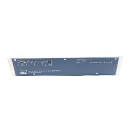
Schweitzer Engineering Laboratories SEL-2BFR Instruction Manual (240 pages)
Breaker Failure Relay and Monitor
Brand:
Schweitzer Engineering Laboratories
| Category:
Relays
| Size: 6 MB
Table of Contents
Table of Contents
9
Section 1: Introduction
5
Introduction
11
Getting Started
11
Overview
11
Relay Features
11
Model Variations
12
2BFR-2 Relay
12
Conventional Terminal Block
12
SEL-2BFR Relay
12
Sel-Bfr
12
Phase Rotation
13
Plug-In Connector
13
System Frequency
13
General Description
13
Table of Contents
17
Date Code
21
Fault Current Element (50FT)
23
MOD Current Element (50MD)
23
Load/Line-Charging Current Element (50LD)
23
Flashover Voltage Element (59FO)
23
Negative-Sequence Overvoltage Element (47Q)
24
Flashover Voltage Element (59H)
24
Voltage Across Closed Breaker Element (Vwarn)
24
Current Unbalance Element (87UB)
24
Overpower Elements (37OP)
24
Breaker Resistor Thermal Elements (26CF, 26CP, 26TF, 26TP)
24
Settable Timers
25
Fixed Timers
25
Logic Inputs
25
Relay Outputs
26
86BF TRIP Output
26
Programmable Outputs (A1, A2, A3, A4, A5)
26
Table 2.1: Logic Input Functions
26
ALARM Output
27
Relay Word
27
Table 2.2: SEL-2BFR Relay Word
27
Table 2.3: Relay Word Bit Definitions
28
Specifications Date Code 20010515
28
Programmable Output Logic
29
Relay Targets
30
Table 2.4: Front-Panel Target Illumination Conditions
30
Signal Processing
31
Logic Description
31
Protection While Tripping Fault Current
32
Scheme 1
32
Scheme 2
33
Scheme 3
33
Scheme 4
34
Scheme 5
34
Scheme 6
35
Figure 2.7: Double-Breaker Arrangement Provides Two Fault Current Sources
37
Protection While Tripping Load or Line-Charging Current
37
Figure 2.8: Failure to Trip Load or Line-Charging Current Logic
38
Thermal Protection of Close and Trip Resistors
39
Figure 2.9: Trip and Close Resistor Thermal Protection Logic
40
Figure 2.10: Protection for Current through an Open Breaker Logic
41
Protection for Current through an Open Breaker (Flashover)
42
Protection for Failure to Close
42
Figure 2.11: Phase Discordance While Closing Logic
43
Time-Delayed Breaker Retrip (SEL-2BFR Relay)
43
Figure 2.12: Time-Delayed Retrip Logic (SEL-2BFR Relay)
44
Time-Delayed Breaker Retrip (SEL-2BFR-2 Relay)
44
86BF Trip and Reset Logic
45
Figure 2.13: Time-Delayed Retrip Logic (SEL-2BFR-2 Relay)
45
Figure 2.14: 86BF TRIP and Reset Logic (MOD Trip Disabled)
45
MOD Trip Disabled
45
Figure 2.15: MOD Trip Disabled Logic Timing Diagram
46
MOD Trip Enabled
46
Figure 2.16: 86BF TRIP, Reset, and MOD Trip Logic (MOD Trip Enabled)
47
52BV Logic
48
Figure 2.17: MOD Trip Enabled Logic Timing Diagram
48
Figure 2.18: 52BV Logic
48
52A Contradicts Voltage
49
Alarm Logic
49
Blown Pot Fuse
49
CB DID Not Close
49
Current after MOD Trip
49
Current While Open
49
Failed CB Close Resistors Put in Service
49
Failed CB Trip Resistors Put in Service
49
Trip While Open
49
MOD Contradicts Current
50
MOD Trip Failed
50
Slow Close
50
Slow Trip
50
Volts Across Closed CB
50
Serial Interfaces
51
IRIG-B Input Description
51
Event Reporting
52
Metering
52
Self-Testing
52
Analog-To-Digital Converter
53
Master Offset
53
Offset
53
Power Supply
53
Random-Access Memory
53
Read-Only Memory
53
Table 2.5: Power Supply Self-Test Limits
53
Programmable Logic Mask Concept
54
Overcurrent Element Operating Time Curves
55
Figure 2.19: Programmable Logic Mask Analogy
55
Figure 2.20: 50FT Pickup Time Curves
56
Figure 2.21: 50FT Dropout Time Curves
56
Figure 2.22: 50MD Pickup Time Curves
57
Figure 2.23: 50MD Dropout Time Curves
57
Figure 2.24: 50LD Pickup Time Curves
58
Figure 2.25: 50LD Dropout Time Curves
58
Specifications
21
General Specifications
21
General
21
Table of Contents
115
Applications
117
Breaker Failure Relaying Overview
117
SEL-2BFR Relay Application
119
Relay AC Current and Voltage Inputs
119
Example Breaker
120
Scheme Overview
120
Setting Selection
121
Select Failure to Trip Fault Current Scheme
121
Select 50FT Overcurrent Element Setting
125
Select Scheme Timer Settings
126
Select 50LD Overcurrent Element Setting
128
Select 62LP and 62LD Settings
128
Select 52A Supervised Breaker Failure Protection Settings
129
Select Time-Delayed Retrip Settings
129
37OP Setting
130
Select Trip and Close Resistor Thermal Element Settings
130
26TF and 26TP Thermal Element Settings
131
Settings
132
47Q Negative-Sequence Overvoltage Element Setting
132
62OP Time Delay Pickup Setting
133
CRTC and TRTC Resistor Cooling Time Constants
133
Select Breaker Pole Flashover Settings
133
62UC Time Delay Pickup Timer Setting
134
87UB Unbalance Current Ratio
134
Select Phase Discordance/Failure to Close Settings
134
50MD Overcurrent Element Setting
135
62UF and 62UP Timer Settings
135
MOD Trip Logic Enabled, Modtrip Equals y
135
Select MOD Trip Logic Setting
135
50MD Overcurrent Element Setting
136
62M1 and 62M2 Timer Settings
136
62M1 Timer Setting
136
MOD Trip Logic Disabled, Modtrip Equals N
136
Select Breaker Monitor Settings Topen, Tclose, Vwarn
136
Select CTR and PTR Settings
136
Example Setting Summary
137
Select Serial Port Timeout Settings TIME1 and TIME2
137
Select the Autoport Setting AUTO
137
Select the External Modem Answer Setting RINGS
137
Example Setting Group
138
Logic Mask Setting Selection
138
Logic Mask M86T
139
M86T Mask Controls the 86BF TRIP Output
139
MER Logic Mask Triggers Event Report Generation
139
Logic Mask MA1
140
Logic Mask MER
140
MA1 Mask Controls the A1 Output, Breaker Operation Alarms
140
Logic Mask MA4
141
Logic Mask MA5
141
MA3 Controls the A3 Output, MOD Trip
141
MA4 Controls the A4 Output, Pending Failure Retrip
141
MA5 Controls the A5 Output, 86BF Reset
141
Other Programmable Output Applications
142
Single-Pole Instantaneous or Time-Delayed Retrip
142
Three-Pole Instantaneous or Time-Delayed Retrip
142
Hot Resistor Indication
143
Loss-Of-Potential Indication
143
Table of Contents
221
Appendix A - Firmware Versions in this Manual
223
Appendix B - Internal Diagrams
225
Appendix C - Sel-Bfr Specifications
227
SEL-BFR General Specifications
227
SEL-BFR Installation
228
Communications Circuits
228
Control Circuits
228
Frame Ground Connection
228
Mounting
228
Power Connections
228
Secondary Circuits
228
EIA-232 Jumpers
229
Jumper Selection
229
Output Contact Soldered Wire Jumpers
229
Password Protection Jumper
229
Remote Control Enable Jumper
229
IRIG-B Installation
230
Advertisement
Advertisement
Related Products
Schweitzer Engineering Laboratories SEL-2BFR-2
Schweitzer Engineering Laboratories SEL-251
Schweitzer Engineering Laboratories SEL-251-2
Schweitzer Engineering Laboratories SEL-251-3
Schweitzer Engineering Laboratories SEL-267D
Schweitzer Engineering Laboratories SEL-221F
Schweitzer Engineering Laboratories SEL-221F-1
Schweitzer Engineering Laboratories SEL-251-1
Schweitzer Engineering Laboratories SEL-251D-1
Schweitzer Engineering Laboratories SEL-251C-1
Schweitzer Engineering Laboratories Categories
Relays
Computer Hardware
Transceiver
Protection Device
Measuring Instruments
More Schweitzer Engineering Laboratories Manuals
Login
Sign In
OR
Sign in with Facebook
Sign in with Google
Upload manual
Upload from disk
Upload from URL