Sign In
Upload
Manuals
Brands
Schweitzer Engineering Laboratories Manuals
Relays
SEL-221F
Schweitzer Engineering Laboratories SEL-221F Manuals
Manuals and User Guides for Schweitzer Engineering Laboratories SEL-221F. We have
1
Schweitzer Engineering Laboratories SEL-221F manual available for free PDF download: Instruction Manual
Schweitzer Engineering Laboratories SEL-221F Instruction Manual (231 pages)
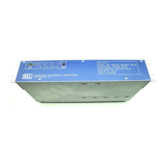
PHASE AND GROUND DISTANCE RELAY; GROUND DIRECTIONAL OVERCURRENT RELAY; SYNCHRONISM CHECKING RELAY; RECLOSING RELAY; FAULT LOCATOR
Brand:
Schweitzer Engineering Laboratories
| Category:
Relays
| Size: 4 MB
Table of Contents
Table of Contents
14
Introduction
20
Getting Started
20
Relay Overview
20
Model Variations Covered by this Instruction Manual
21
Other SEL-221F Relay Model Variations
22
General Description
22
Figure 1.1: System Single Line Diagram for the SEL-221F-1 Relay Modification Explanation
22
Explanation
22
Specifications
25
Table 2.1: Relay Word
25
Relay Standards and Input Parameters
26
Functional Specifications
27
Figure 2.1: Three Zones of Phase and Ground Mho Distance Protection
28
Detailed Specifications
32
Figure 2.2: 32Q Polarization Criteria
35
Table 2.2: Logic Input Functions
37
Table 2.3: LOPE Settings
42
Table 2.4: Relay Word Bit Summary
46
Table 2.5: Power Supply Self Test Limits
54
Functional Description
56
Table 2.6: Self Test Summary
56
Figure 2.4: Self-Polarized Mho Element Reach at Maximum Torque Angle
57
Figure 2.5: Phase-Phase Element Response for a Three-Phase Forward Fault
58
Figure 2.6: Phase-Phase Element Response for a Phase-Phase Forward Fault
58
Table 2.7: Voltages and Currents for Mho Elements AG, BG, CG, AB, BC, CA
59
Figure 2.7: Phase-Ground Element Response for a Phase-Ground Forward Fault
59
Figure 2.8: Positive-Sequence Polarizing Voltage Block Diagram
60
Table 2.8: Directional Element Torque Equations
61
Figure 2.9: Programmable Logic Mask Analogy
62
Relay Element Operating Time Curves
63
Figure 2.10: Phase and Ground Distance Element Speed Curves
63
Time-Overcurrent Curve Equations
64
Figure 2.11: Residual Time-Overcurrent Element Moderately Inverse Time
65
Figure 2.12: Residual Time-Overcurrent Element Inverse Time Characteristic (Curve 2)
66
Figure 2.13: Residual Time-Overcurrent Element very Inverse Time
67
Figure 2.14: Residual Time-Overcurrent Element Extremely Inverse Time
68
Communications
73
Introduction
74
Serial Port Connections and Configurations
74
Communications Protocol
76
Command Characteristics
78
Command Descriptions
80
Table 3.2: Hexadecimal/Binary Conversion
87
Table 3.3: Target LED Assignment
88
Figure 2.3: Relay Targets
88
Event Reporting
99
Event Report Generation
99
Table 4.1: Event Report Triggering Actions
99
Table 4.2: Non-Event Report Triggering Actions
99
Summary Event Report
100
Long Event Report
103
Example Event Reports
107
Figure 4.1: Example System Single-Line Diagram
109
Firmware Identification
113
Tables
115
Applications
116
Relay Application Overview
116
230 Kv SETTING EXAMPLE
118
Figure 5.2: Sync-Check Window
125
Figure 5.3: 52A Input and 52BT Timing Diagram
137
Figure 5.4: Faulted Line with All Sources in
138
Figure 5.5: Faulted System with Breakers 1 and 2 Closed
139
Figure 5.6: Faulted System with Breaker 2 Open
139
Table 5.1: Settings For: Bus B, 230 Kv Breaker 3
145
Reclosing Relay Operation Examples
151
Table 5.2: Reclosing Relay Timing Examples
151
Figure 5.7: Single Shot Unsupervised Reclose Sequence
152
Table 5.3: Recloser Settings for Examples 1 and 2
152
Figure 5.8: Reclosing Cancelled Due to RC Assertion
153
Figure 5.9: Live Bus\Dead-Line Supervised Reclose
154
Table 5.4: Recloser Settings for Example 3
154
Table 5.5: Recloser Settings for Example 4
155
Figure 5.10: Sync-Check Supervised Reclose Sequence
156
Setting Sheets
157
Installation
163
Installation Checkout
163
SEL Direction and Polarity Check Form
163
Figure 6.1: Nine-Pin Connector Pin Number Convention
163
Table 6.1: Pin Definition
167
Figure 6.3: Relay Dimensions, Panel Cutout, and Drill Plan
171
Figure 6.4: Communications and Clock Connections - One Unit at One Location
172
Figure 6.5: Communications and Clock Connections - Multiple Units at One Location
172
Figure 6.6: SEL Relay Communications Diagram for Connection to the SEL-DTA
173
Figure 6.7: External Current and Voltage Connections
173
Figure 6.8: DC External Connection Diagram (Typical)
174
SEL Direction and Polarity Check Form
175
Maintenance & Testing
177
Test Procedures
179
Initial Checkout
181
Figure 7.1: Relay Part Number and Hardware Identification Sticker
182
Figure 7.2: Communication Interface Setup
183
Table 7.1: Fault Locator Test Values
188
Table 7.2: Output Contact and Target LED Results
188
Full Functional Test
190
Setting Test
190
Meter Test
192
Figure 7.3: METER Test Connections
192
Mho Element Testing
193
Figure 7.4: Example ONEBUS Input Data for Phase-Phase and Ground Faults
194
Figure 7.5: Example ONEBUS Result Screen for Phase-Phase and Ground Faults
194
Figure 7.6: Example ONEBUS Input Data for Three-Phase Faults
195
Table 7.3: Three-Phase Fault Voltages and Currents at MTA
196
Table 7.4: Zone 1 Three-Phase Fault Test Quantities at MTA
198
Table 7.5: Zone 1 Three-Phase Fault Test Quantities at MTA +45
199
Figure 7.9A: Three-Phase Voltage and Two-Phase Current Source Test Connections for Phase-Phase Mho Test
201
Table 7.6: Zone 1 Phase-Phase Test Voltages and Currents, BC Fault
202
Table 7.7: Zone 1 Phase-Phase Test Quantities at MTA +45
203
Table 7.8: Zone 1 Ground Element Test Quantities, AG Fault
204
Directional Element Tests
206
Table 7.9: Zone 1 Phase-Ground Test Quantities at MTA+ 45
206
Table 7.10: 32Q Test Voltages
206
Figure 7.11: Three Voltage Vs. One Voltage for Directional Tests
207
Residual Overcurrent Element Tests
208
Residual Time-Overcurrent Element Timing Tests
208
Phase Overcurrent Element Tests
209
Table 7.11: Current Quantities for 51N Timing Test Example
209
Loss-Of-Potential Test
210
Table 7.12: Conditions to Test the SET LOP and CLEAR LOP Logic
210
Z2DG and Z3DG Timer Tests
211
Table 7.13: Standard Zone 2 AG Fault Using Factory Relay Settings
211
Table 7.14: Standard Zone 3 AG Fault Using Factory Relay Settings
211
Z2DP Timer Test
212
Table 7.15: Standard Zone 2 BC Fault Using Factory Relay Settings
212
Remote-End-Just-Opened Tests
213
Switch-Onto-Fault Tests
214
Table 7.16: Zone 2 AG Fault Quantities
214
Recloser Test
215
Table 7.17: 1AG Fault
215
Synchronizing and Polarizing Voltage Element Tests
216
Voltage Checking Logic Tests
216
Synchronism Checking Logic Tests
217
Input Circuits Test
218
Serial Ports Test
219
IRIG-B Time Code Input Test
219
Table 7.18: Contact Inputs and Terminal Numbers
219
Power Supply Voltages Test
220
Calibration
220
Troubleshooting
221
Firmware Upgrade Instructions
224
Program to Compute Test Set Settings for Testing Distance Relays
226
Appendices
228
Parts Placement Diagram
228
Advertisement
Advertisement
Related Products
Schweitzer Engineering Laboratories SEL-2BFR
Schweitzer Engineering Laboratories SEL-2BFR-2
Schweitzer Engineering Laboratories SEL-251
Schweitzer Engineering Laboratories SEL-251-2
Schweitzer Engineering Laboratories SEL-251-3
Schweitzer Engineering Laboratories SEL-267D
Schweitzer Engineering Laboratories SEL-221F-1
Schweitzer Engineering Laboratories SEL-251-1
Schweitzer Engineering Laboratories SEL-251D-1
Schweitzer Engineering Laboratories SEL-251C-1
Schweitzer Engineering Laboratories Categories
Relays
Computer Hardware
Transceiver
Protection Device
Measuring Instruments
More Schweitzer Engineering Laboratories Manuals
Login
Sign In
OR
Sign in with Facebook
Sign in with Google
Upload manual
Upload from disk
Upload from URL