Sign In
Upload
Manuals
Brands
SCHUNK Manuals
Industrial Equipment
PPU-E
SCHUNK PPU-E Manuals
Manuals and User Guides for SCHUNK PPU-E. We have
2
SCHUNK PPU-E manuals available for free PDF download: Assembly And Operating Manual
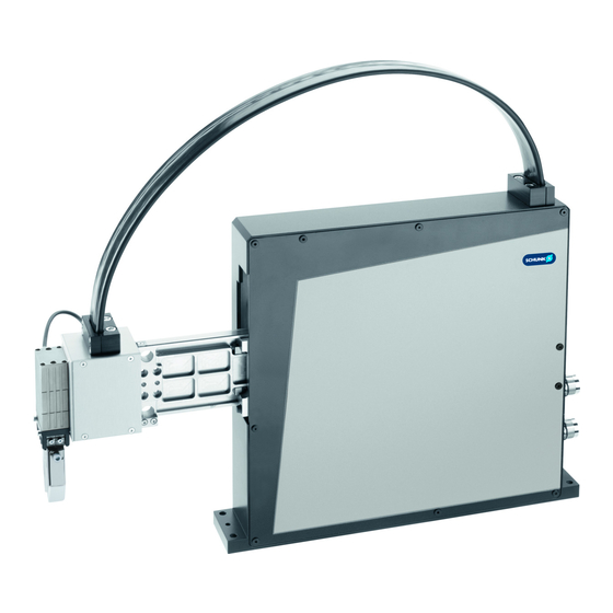
SCHUNK PPU-E Assembly And Operating Manual (148 pages)
Electric Pick & Place Unit
Brand:
SCHUNK
| Category:
Industrial Equipment
| Size: 6 MB
Table of Contents
Deutsch
7
Table of Contents
7
1 Allgemein
10
Zu dieser Anleitung
10
Darstellung der Warnhinweise
10
Mitgeltende Unterlagen
11
Lieferumfang
11
Gewährleistung
11
Zubehör
11
2 Grundlegende Sicherheitshinweise
12
Bestimmungsgemäße Verwendung
12
Vernünftigerweise Vorhersehbare Fehlanwendung
12
Bauliche Veränderungen
12
Ersatzteile
12
Umgebungs- und Einsatzbedingungen
13
Personalqualifikation
13
Persönliche Schutzausrüstung
14
Schilder am Antrieb
15
Grundsätzliche Gefahren
15
Schutz bei Handhabung und Montage
16
Schutz bei Inbetriebnahme und Betrieb
16
Schutz vor Gefährlichen Bewegungen
17
Schutz vor Stromschlag
17
Hinweise auf Besondere Gefahren
18
3 Produktbeschreibung
21
Baugrößen
21
Typenschlüssel
22
Technische Daten
23
Zulässige Statische Belastung
24
4 Transport und Lagerung
25
Transport
25
Lagerung
25
5 Beschreibung der Versionen und Optionen
26
Version mit Integrierten Ventilen 2X2 (PF2), 2X4 (PF4), 2X6 (PF6)
26
Version mit Zusätzlicher C-Achse (C04
28
Version mit Venturidüse (VAF)
29
Option Federrückstellung (FA)
29
Option Haltebremse (BV)
30
6 Montage
31
Mechanischer Anschluss
31
Mechanischer Anschluss des Moduls PPU-E 15
32
Mechanischer Anschluss des Moduls PPU-E 30
33
Mechanischer Anschluss des Moduls PPU-E 50
34
Mechanischer Anschluss Basisschnittstelle (A02)
35
Mechanischer Anschluss Baukastenschnittstelle (A01)
36
Mechanischer Anschluss C-Achse - Schnittstelle (C04
37
Elektrischer Anschluss
38
Erdung PE
39
Anschlüsse am Backpanel
39
Anschlüsse am Backpanel - Option C-Achse (C04
40
Inkrementelles Messsystem LE 100
41
Inkrementelles Messsystem LE200
42
Absolutes Messsystem TTK70
43
Absolutes Messsystem MSA111C
44
Inkrementelles Messsystem Encoder Kit R
45
Absolutes Messsystem SKM36S
46
Motor
47
E/A Schnittstelle Grenzbelastbarkeit
48
E/A Schnittstelle für Basis- und Baukasten-Versionen
49
E/A Schnittstelle für C-Achse (C04
50
E/A Schnittstelle für Venturidüse (VAF)
51
Sensoreingangsstecker 3Pol und 4Pol
52
Pneumatikanschluss / Pneumatikpläne
54
Pneumatikplan Version Basis und Baukasten 2X2 (PF2), 2X4 (PF4), 2X6 (PF6)
55
Pneumatikplan Version C-Achse
56
Pneumatikplan Version Venturidüse
57
Pneumatikplan Version Vakuumpumpe
58
Option Haltebremse
59
7 Instandsetzung
60
8 Wartung
62
Pflege
64
Kontrollarbeiten
64
Wartung PPU-E 15
65
Wartung PPU-E 30 und PPU-E 50
67
9 Fehlerbehebung
69
Produkt Bewegt sich nicht
69
Produkt Erreicht die Zykluszeiten nicht
69
Produkt wird zu Warm
69
Achse Fällt nach Unten
69
10 Ersatzteile
70
Hinweis zur Bestellung von Ersatzteilen
70
Verschleißteile
70
Hilfsmittel
71
11 Einbauerklärung
72
Anlage zur Einbauerklärung
73
English
78
1 General
81
About this Manual
81
Presentation of Warning Labels
81
Applicable Documents
82
Scope of Delivery
82
Warranty
82
Accessories
82
2 Basic Safety Notes
83
Intended Use
83
Reasonably Foreseeable Misuse
83
Constructional Changes
83
Spare Parts
83
Ambient Conditions and Operating Conditions
84
Personnel Qualification
84
Personal Protective Equipment
85
Signs on the Drive
85
Fundamental Dangers
86
Protection During Handling and Assembly
86
Protection During Commissioning and Operation
86
Protection against Dangerous Movements
87
Protection against Electric Shock
87
Notes on Particular Risks
88
3 Product Description
91
Sizes
91
Type Code
92
Technical Data
93
Permissible Static Load
94
4 Transport and Storage
95
Transportation
95
Storage
95
5 Description of the Versions and Options
96
Version with Integrated Valves 2X2 (PF2), 2X4 (PF4), 2X6 (PF6)
96
Version with Additional C-Axis (C04
98
Version with Venturi Nozzle (VAF)
99
Optional Spring Return (FA)
99
Optional Holding Brake (BV)
100
6 Assembly
101
Mechanical Connection of the Module
101
Mechanical Connection of the PPU-E 15 Module
102
Mechanical Connection of the PPU-E 30 Module
103
Mechmechanical Connection of the PPU-E 50 Module
104
Mechanical Connection of Basic Interface (A02)
105
Mechanical Connection of the Modular System Interface (A01)
106
Mechanical Connection C-Axis Interface (C04
107
Electrical Connection
108
PE Ground
109
Connections on the Back Panel
110
Connection on the Back Panel - Optional C-Axis (C04
111
Incremental Measuring System LE100
112
Incremental Measuring System LE200
113
Absolute Measuring System TTK70
114
MSA111C Absolute Measuring System
115
Incremental Measuring System Encoder Kit R
116
Absolute Measuring System SKM36S
117
Motor
118
I/O Interface for Critical Load
119
I/O Interface for Basic and Modular System Versions
120
I/O Interface for C-Axis (C04
121
I/O Interface for Venturi Nozzles (VAF)
122
Sensor Input Plug 3-Pin and 4-Pin
123
Pneumatic Connection / Pneumatic Diagrams
125
Pneumatic Diagram for Basic and Modular System Version 2X2 (PF2), 2X4 (PF4), 2X6 (PF6)
126
Pneumatic Diagram for C-Axis Version
127
Pneumatic Diagram for Venturi Nozzle Version
128
Pneumatic Diagram for Vacuum Pump Version
129
Optional Holding Brake
130
7 Servicing
131
8 Maintenance
133
Care
135
Checks
135
Maintenance of PPU-E 15
136
Maintenance of PPU-E 30 and PPU-E 50
138
9 Troubleshooting
140
Product Does Not Move
140
Product Does Not Achieve the Cycle Times
140
Product Gets too Hot
140
Axis Drops down
140
10 Spare Parts
141
Note Regarding Spare Part Orders
141
Wearing Parts
141
Aid
142
11 Translation of Original Declaration of Incorporation
143
Annex to Declaration of Incorporation
144
Advertisement
SCHUNK PPU-E Assembly And Operating Manual (144 pages)
Electric Pick & Place Unit
Brand:
SCHUNK
| Category:
Industrial Equipment
| Size: 7 MB
Table of Contents
Deutsch
5
Table of Contents
5
Darstellung der Warnhinweise
8
Allgemein
8
Zu dieser Anleitung
8
Mitgeltende Unterlagen
9
Lieferumfang
9
Gewährleistung
9
Zubehör
9
Grundlegende Sicherheitshinweise
10
Bestimmungsgemäße Verwendung
10
Vernünftigerweise Vorhersehbare Fehlanwendung
10
Bauliche Veränderungen
10
Personalqualifikation
11
Umgebungs- und Einsatzbedingungen
11
Ersatzteile
11
Persönliche Schutzausrüstung
12
Schilder am Antrieb
13
Grundsätzliche Gefahren
14
Schutz bei Handhabung und Montage
14
Schutz bei Inbetriebnahme und Betrieb
14
Schutz vor Gefährlichen Bewegungen
15
Schutz vor Stromschlag
15
Hinweise auf Besondere Gefahren
16
Produktbeschreibung
18
Baugrößen
18
Typenschlüssel
19
Technische Daten
20
Zulässige Statische Belastung
21
Hilfs- und Schmierstoffe (Optional: H1-Zertifiziert)
22
Transport und Lagerung
23
Transport
23
Lagerung
23
Version mit Integrierten Ventilen 2X2 (PF2), 2X4 (PF4), 2X6 (PF6)
24
Beschreibung der Versionen und Optionen
24
Version mit Zusätzlicher C-Achse (C04
26
Version mit Venturidüse (VAF)
27
Option Federrückstellung (FA)
27
Option Haltebremse (BV)
28
Montage
29
Mechanischer Anschluss
29
Mechanischer Anschluss des Moduls PPU-E 15
30
Mechanischer Anschluss des Moduls PPU-E 30
31
Mechanischer Anschluss des Moduls PPU-E 50
32
Mechanischer Anschluss Basisschnittstelle (A02)
33
Mechanischer Anschluss Baukastenschnittstelle (A01)
34
Mechanischer Anschluss C-Achse - Schnittstelle (C04
35
Elektrischer Anschluss
36
Erdung PE
37
Anschlüsse am Backpanel
38
Anschlüsse am Backpanel - Option C-Achse (C04
39
Inkrementelles Messsystem le 100
40
Inkrementelles Messsystem LE200
41
Absolutes Messsystem TTK70 / TTK70S
42
Absolutes Messsystem MSA111C
43
Inkrementelles Messsystem Encoder Kit R
44
Absolutes Messsystem SKM36S
45
Motor
46
E/A Schnittstelle Grenzbelastbarkeit
47
E/A Schnittstelle für Basis- und Baukasten-Versionen
48
E/A Schnittstelle für C-Achse (C04
49
E/A Schnittstelle für Venturidüse (VAF)
50
Sensoreingangsstecker 3Pol und 4Pol
51
Pneumatikanschluss / Pneumatikpläne
53
Pneumatikplan Version Basis und Baukasten 2X2 (PF2), 2X4 (PF4), 2X6 (PF6)
54
Pneumatikplan Version C-Achse
55
Pneumatikplan Version Venturidüse
56
Pneumatikplan Version Vakuumpumpe
56
Option Haltebremse
57
Instandsetzung
58
Wartung
60
Pflege
62
Kontrollarbeiten
63
Wartung PPU-E 15
63
Wartung PPU-E 30 und PPU-E 50
65
Achse Fällt nach Unten
67
Produkt wird zu Warm
67
Produkt Erreicht die Zykluszeiten nicht
67
Produkt Bewegt sich nicht
67
Fehlerbehebung
67
Ersatzteile
68
Hinweis zur Bestellung von Ersatzteilen
68
Verschleißteile
68
Hilfsmittel
69
Einbauerklärung
70
Information zur Rohs-Richtlinie, REACH-Verordnung und zu Besonders Besorgniserregenden Inhaltsstoffen (SVHC)
71
English
74
About this Manual
77
General
77
Presentation of Warning Labels
77
Accessories
78
Applicable Documents
78
Scope of Delivery
78
Warranty
78
Basic Safety Notes
79
Constructional Changes
79
Intended Use
79
Reasonably Foreseeable Misuse
79
Spare Parts
79
Ambient Conditions and Operating Conditions
80
Personnel Qualification
80
Personal Protective Equipment
81
Signs on the Drive
82
Fundamental Dangers
83
Protection During Commissioning and Operation
83
Protection During Handling and Assembly
83
Protection against Dangerous Movements
84
Protection against Electric Shock
84
Notes on Particular Risks
85
Product Description
87
Sizes
87
Type Code
88
Technical Data
89
Permissible Static Load
90
Auxiliary Materials and Lubricants (Optional: H1 Certified)
91
Storage
92
Transport
92
Transport and Storage
92
Description of the Versions and Options
93
Version with Integrated Valves 2X2 (PF2), 2X4 (PF4), 2X6 (PF6)
93
Version with Additional C-Axis (C04
95
Optional Spring Return (FA)
96
Version with Venturi Nozzle (VAF)
96
Optional Holding Brake (BV)
97
Assembly
98
Mechanical Connection of the Module
98
Mechanical Connection of the PPU-E 15 Module
99
Mechanical Connection of the PPU-E 30 Module
100
Mechmechanical Connection of the PPU-E 50 Module
101
Mechanical Connection of Basic Interface (A02)
102
Mechanical Connection of the Modular System Interface (A01)
103
Mechanical Connection C-Axis Interface (C04
104
Electrical Connection
105
PE Ground
106
Connections on the Back Panel
107
Connection on the Back Panel - Optional C-Axis (C04
108
Incremental Measuring System LE100
109
Incremental Measuring System LE200
110
Absolute Measuring System TTK70 / TTK70S
111
MSA111C Absolute Measuring System
112
Incremental Measuring System Encoder Kit R
113
Absolute Measuring System SKM36S
114
Motor
115
I/O Interface for Critical Load
116
I/O Interface for Basic and Modular System Versions
117
I/O Interface for C-Axis (C04
118
I/O Interface for Venturi Nozzles (VAF)
119
Sensor Input Plug 3-Pin and 4-Pin
120
Pneumatic Connection / Pneumatic Diagrams
122
Pneumatic Diagram for Basic and Modular System Version 2X2 (PF2), 2X4 (PF4), 2X6 (PF6)
123
Pneumatic Diagram for C-Axis Version
124
Pneumatic Diagram for Vacuum Pump Version
125
Pneumatic Diagram for Venturi Nozzle Version
125
Optional Holding Brake
126
Servicing
127
Maintenance
129
Care
131
Checks
131
Maintenance of PPU-E 15
132
Maintenance of PPU-E 30 and PPU-E 50
134
Axis Drops down
136
Product Does Not Achieve the Cycle Times
136
Product Does Not Move
136
Product Gets too Hot
136
Troubleshooting
136
Note Regarding Spare Part Orders
137
Spare Parts
137
Wearing Parts
137
Aid
138
Translation of Original Declaration of Incorporation
139
UKCA Declaration of Incorporation
140
Information on the Rohs Directive, REACH Regulation and Substances of very High Concern (SVHC)
141
Advertisement
Related Products
SCHUNK PPU-P
SCHUNK PPD
SCHUNK PFH 250
SCHUNK VERO-S NSE plus 90
SCHUNK VERO-S NSE plus 99
SCHUNK VERO-S NSL plus 150-V1
SCHUNK PGL-plus-P 20
SCHUNK PHL-W 63
SCHUNK PRH 060-100
SCHUNK PFH 300
SCHUNK Categories
Industrial Equipment
Power Tool
Control Unit
Accessories
Tools
More SCHUNK Manuals
Login
Sign In
OR
Sign in with Facebook
Sign in with Google
Upload manual
Upload from disk
Upload from URL