Sign In
Upload
Manuals
Brands
SCHUNK Manuals
Engine
LDN-DS-0200
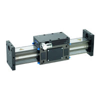
SCHUNK LDN-DS-0200 Linear Motor Drive Manuals
Manuals and User Guides for SCHUNK LDN-DS-0200 Linear Motor Drive. We have
2
SCHUNK LDN-DS-0200 Linear Motor Drive manuals available for free PDF download: Assembly And Operating Manual
SCHUNK LDN-DS-0200 Assembly And Operating Manual (148 pages)
Linear Motor Axis
Brand:
SCHUNK
| Category:
Engine
| Size: 7 MB
Table of Contents
Deutsch
5
Table of Contents
5
1 Allgemein
8
Zu dieser Anleitung
8
Darstellung der Warnhinweise
8
Mitgeltende Unterlagen
9
Gewährleistung
9
Lieferumfang
9
Zubehör
9
Optionales Zubehör
10
2 Grundlegende Sicherheitshinweise
11
Bestimmungsgemäße Verwendung
11
Vernünftigerweise Vorhersehbare Fehlanwendung
11
Bauliche Veränderungen
11
Ersatzteile
11
Umgebungs- und Einsatzbedingungen
12
Personalqualifikation
12
Persönliche Schutzausrüstung
13
Hinweise zum Sicheren Betrieb
13
Transport
14
Störungen
14
Entsorgung
14
Warnschilder am Antrieb
15
Grundsätzliche Gefahren
15
Schutz bei Handhabung und Montage
16
Schutz bei Inbetriebnahme und Betrieb
16
Schutz vor Gefährlichen Bewegungen
17
Schutz vor Stromschlag
18
Hinweise auf Besondere Gefahren
19
3 Technische Daten
21
Typenübersicht
22
Typenschlüssel
24
Zulässige Statische Belastung
25
4 Transport und Lagerung
26
Transport
26
Lagerung
26
5 Beschreibung der Optionen
27
Option Halterbremse
27
Option Schaltventil
28
Option StoßDämpfer
28
Option Abstreifer
28
Option Endschalter und Referenzschalter
28
6 Montage
29
Mechanischer Anschluss des Moduls
29
Abmessungen
31
Elektrischer Anschluss
33
Erdung PE
34
Elektrische Anschlüsse am Schlitten
34
Inkrementelles Messsystem LE100 M12
35
Inkrementelles Messsystem LE100
36
Absolutes Messsystem MSA111C-DQ
37
Absolutes Messsystem TTK70 / TTK70S
38
Absolutes Messsystem MSA111C
39
Motor
40
Pneumatischer Anschluss (nur bei Haltebremse)
41
7 Wartung und Instandsetzungsarbeiten
43
Übersicht
45
Motorgehäuse Wechseln
45
Motorgehäuse Ausbauen
47
Motorgehäuse Einbauen
47
Motorstecker Drehen
47
Motorstecker auf Gegenüber Liegende
48
Motordrehrichtung
50
Führungsschlitten - Stützrollen auf Exzenterseite Wechseln
51
Führungsschlitten - Stützrollen auf Festlagerseite Wechseln
52
Wegmesssystem Wechseln
54
Magnetband LE100 Wechseln
54
Abstreifer Wechseln
55
Haltebremse Tauschen
56
Endschalter und Referenzschalter
58
Pflege
59
Kontrollarbeiten
59
8 Fehlerbehebung
60
Produkt Bewegt sich nicht
60
Produkt Erreicht die Zykluszeiten nicht
60
Produkt wird zu Warm
60
9 Ersatzteile
61
Hinweis zur Bestellung von Ersatzteilen
61
Verschleißteile
61
Achsen
62
Motoren
63
Führung
66
Messsystem
67
Haltebremse
68
Zubehör
69
Hilfsmittel
70
10 Einbauerklärung
71
Anlage zur Einbauerklärung
72
English
77
1 General
80
About this Manual
80
Presentation of Warning Labels
80
Applicable Documents
81
Warranty
81
Scope of Delivery
81
Accessories
81
Optional Accessories
82
2 Basic Safety Notes
83
Intended Use
83
Reasonably Foreseeable Misuse
83
Constructional Changes
83
Spare Parts
83
Ambient Conditions and Operating Conditions
84
Personnel Qualification
84
Personal Protective Equipment
85
Notes on Safe Operation
85
Transport
85
Malfunctions
86
Disposal
86
Warnings on the Drive
86
Fundamental Dangers
87
Protection During Handling and Assembly
87
Protection During Commissioning and Operation
87
Protection against Dangerous Movements
88
Protection against Electric Shock
89
Notes on Particular Risks
90
3 Technical Data
93
Overview of Types
93
Type Code
95
Permissible Static Load
96
4 Transport and Storage
97
Transport
97
Storage
97
5 Description of the Options
98
Optional Holding Break
98
Optional Switching Valve
99
Optional Shock Absorbers
99
Optional Wipers
99
Optional Limit and Reference Switches
99
6 Assembly
100
Mechanical Connection of the Module
100
Dimensions
102
Electrical Connection
104
PE Ground
105
Electrical Connections at the Slide
105
LE100 M12 Incremental Measuring System
106
LE100 Incremental Measuring System
107
MSA111C-DQ Absolute Measuring System
108
Absolute Measuring System TTK70 / TTK70S
109
MSA111C Absolute Measuring System
110
Motor
111
Pneumatic Connection (Only for the Holding Brake)
112
7 Maintenance and Repair Work
114
Overview
115
Changing the Motor Housing
116
Uninstalling the Motor Housing
117
Installing the Motor Housing
117
Turning the Motor Plug
117
Mounting the Motor Plug on the Opposite Side
119
Motor Rotation Direction
121
Guided Slide - Changing the Support Rollers on the Eccentric Side
122
Guided Slide - Changing the Support Rollers on the Locating Bearing Side
123
Changing the Stroke Measuring System
124
Changing the Magnetic Strip
125
Changing the Wipers
127
Replacing the Holding Brake
128
Limit Switches and Reference Switches
130
Care
131
Checks
131
8 Troubleshooting
132
Product Does Not Move
132
Product Does Not Achieve the Cycle Times
132
Product Gets too Hot
132
9 Spare Parts
133
Note Regarding Spare Part Orders
133
Wearing Parts
133
Axes
134
Motors
135
Guide
138
Measuring System
139
Holding Brake
140
Accessories
141
Aids
142
10 Translation of Original Declaration of Incorporation
143
Annex to Declaration of Incorporation
144
Advertisement
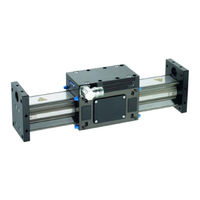
SCHUNK LDN-DS-0200 Assembly And Operating Manual (146 pages)
Linear motor axis
Brand:
SCHUNK
| Category:
Industrial Equipment
| Size: 7 MB
Table of Contents
Deutsch
7
Table of Contents
7
1 Zu dieser Anleitung
10
Warnhinweise
10
Mitgeltende Unterlagen
11
2 Grundlegende Sicherheitshinweise
12
Bestimmungsgemäße Verwendung
12
Vernünftigerweise Vorhersehbare Fehlanwendung
12
Umgebungs- und Einsatzbedingungen
12
Produktsicherheit
13
Schutzeinrichtungen
13
Bauliche Veränderungen
13
Personalqualifikation
13
Warnschilder am Antrieb
15
Verwendung von Persönlichen Schutzausrüstungen
15
Hinweise auf Besondere Gefahren
16
3 Gewährleistung
18
4 Lieferumfang
18
5 Zubehör
18
Optionales Zubehör
18
6 Produktbeschreibung
19
Typenübersicht
19
Nomenklatur
21
Technische Daten
22
Zulässige Statische Belastung
23
7 Transport, Lagerung und Entsorgung
24
Transport
24
Lagerung
24
Entsorgung
24
8 Beschreibung der Optionen
25
Option Halterbremse
25
Option Schaltventil
26
Option StoßDämpfer
26
Option Abstreifer
26
Option Endschalter und Referenzschalter
26
9 Montage
27
Mechanischer Anschluss des Moduls
27
Abmessungen
29
Elektrischer Anschluss
31
Erdung PE
32
Elektrische Anschlüsse am Schlitten
32
Inkrementelles Messsystem LE100 M12
33
Inkrementelles Messsystem LE100
34
Absolutes Messsystem MSA111C-DQ
35
Absolutes Messsystem TTK70
36
Absolutes Messsystem MSA111C
37
Motor
38
Pneumatischer Anschluss (nur bei Haltebremse)
39
10 Wartung und Instandsetzungsarbeiten
41
Übersicht
42
Motorgehäuse Wechseln
43
Motorgehäuse Ausbauen
44
Motorgehäuse Einbauen
44
Motorstecker Drehen
45
Motorstecker auf Gegenüber Liegende
46
Motordrehrichtung
48
Führungsschlitten - Stützrollen auf Exzenterseite Wechseln
49
Führungsschlitten - Stützrollen auf Festlagerseite Wechseln
50
Wegmesssystem Wechseln
51
Hauptkomponenten
51
Messsystem LE100 Wechseln
53
Messsystem TTK 70 Wechseln
54
Magnetband LE100 Wechseln
55
Abstreifer Wechseln
56
Haltebremse Tauschen
57
Endschalter und Referenzschalter
59
Pflege
60
Kontrollarbeiten
60
11 Fehlerbehebung
61
Produkt Bewegt sich nicht
61
Produkt Erreicht die Zykluszeiten nicht
61
Produkt wird zu Warm
61
12 Ersatzteile
62
Hinweis zur Bestellung von Ersatzteilen
62
Verschleißteile
62
Achsen
63
Motoren
64
Führung
67
Messsystem
68
Haltebremse
69
Zubehör
70
Hilfsmittel
70
13 Einbauerklärung
71
Anlage zur Einbauerklärung
72
English
77
1 About this Manual
80
Warnings
80
Applicable Documents
81
2 Basic Safety Notes
82
Intended Use
82
Reasonably Foreseeable Misuse
82
Ambient Conditions and Operating Conditions
82
Product Safety
83
Protective Equipment
83
Constructional Changes
83
Personnel Qualification
83
Warnings on the Drive
85
Using Personal Protective Equipment
85
Notes on Particular Risks
86
3 Warranty
88
4 Scope of Delivery
88
5 Accessories
88
Optional Accessories
88
6 Product Description
89
Overview of Types
89
Nomenclature
91
Technical Data
92
Permissible Static Load
93
7 Transport, Storage and Disposal
94
Transport
94
Storage
94
Disposal
94
8 Description of the Options
95
Optional Holding Break
95
Optional Switching Valve
96
Optional Shock Absorbers
96
Optional Wipers
96
Optional Limit and Reference Switches
96
9 Assembly
97
Mechanical Connection of the Module
97
Dimensions
99
Electrical Connection
101
PE Ground
102
Electrical Connections at the Slide
102
LE100 M12 Incremental Measuring System
103
LE100 Incremental Measuring System
104
MSA111C-DQ Absolute Measuring System
105
TTK70 Absolute Measuring System
106
MSA111C Absolute Measuring System
107
Motor
108
Pneumatic Connection (Only for the Holding Brake)
109
10 Maintenance and Repair Work
111
Overview
112
Changing the Motor Housing
113
Uninstalling the Motor Housing
114
Installing the Motor Housing
114
Turning the Motor Plug
115
Mounting the Motor Plug on the Opposite Side
116
Motor Rotation Direction
118
Guided Slide - Changing the Support Rollers on the Eccentric Side
119
Guided Slide - Changing the Support Rollers on the Locating Bearing Side
120
Changing the Stroke Measuring System
121
Main Components
121
Changing the Measuring System LE 100
123
Changing Measuring System TTK 70
124
Changing the Magnetic Strip
125
Changing the Wipers
126
Replacing the Holding Brake
127
Limit Switches and Reference Switches
129
Care
130
Checks
130
11 Troubleshooting
131
Product Does Not Move
131
Product Does Not Achieve the Cycle Times
131
Product Gets too Hot
131
12 Spare Parts
132
Note Regarding Spare Part Orders
132
Wearing Parts
132
Axes
133
Motors
134
Guide
137
Measuring System
138
Holding Brake
139
Accessories
140
Aids
140
13 Translation of Original Declaration of Incorporation
141
Annex to Declaration of Incorporation
142
Advertisement
Related Products
SCHUNK LDN-DS Series
SCHUNK LDN-DL Series
SCHUNK LDN-DG
SCHUNK LDN-DL-0400
SCHUNK LDN-DG-0600
SCHUNK LDN Series
SCHUNK LDN L Series
SCHUNK LDN-ES-0100
SCHUNK LDN-UL-0200
SCHUNK LDN-EG-0300
SCHUNK Categories
Industrial Equipment
Power Tool
Control Unit
Accessories
Tools
More SCHUNK Manuals
Login
Sign In
OR
Sign in with Facebook
Sign in with Google
Upload manual
Upload from disk
Upload from URL