Sign In
Upload
Manuals
Brands
Sakai Manuals
Construction Equipment
SV400FB-2
User Manuals: Sakai SV400FB-2 Soil Compactor
Manuals and User Guides for Sakai SV400FB-2 Soil Compactor. We have
1
Sakai SV400FB-2 Soil Compactor manual available for free PDF download: Shop Manual
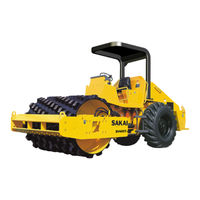
Sakai SV400FB-2 Shop Manual (218 pages)
Brand:
Sakai
| Category:
Construction Equipment
| Size: 16 MB
Table of Contents
Table of Contents
5
Safety
11
General Safety
13
Understanding the Safety Symbols and Signal Words
13
General
13
Qualifications of Operators and Maintenance Personnel
14
Safety Practices and Policies
14
Pre Start Inspection
15
Safety Instructions
15
Starting
15
Operating
15
Stopping
16
Maintenance
16
Transporting the Machine
18
Specifications
19
Specification Data 1-1. Sv400D-2
21
Sv400T-2
23
Sv400Tb-2
25
Sv400Tf-2
27
Sv400Fb-2
29
Specifications and Setting
31
Engine
31
Propulsion
31
Hydraulic Devices
32
Steering Devices
32
Brakes
33
Oil and Grease Capacity
33
Fuel and Lubricants Specification
34
Rating
34
Recommended Lubricants
34
Tightening Torque Chart
35
Engine and Controls
37
Engine
39
Engine Mount
39
Engine Exterior
40
Cooling System
41
Control System
42
Throttle Control
42
Forward-Reverse Control
43
Pump Mount
44
Pump Attachment
45
Hydraulic Systems
47
System Circuit Diagram
50
Graphic Symbols for Hydraulic
50
Hydraulic Circuit Diagram (SV400D/T/TF-2)
53
Hydraulic Circuit Diagram (SV400TB/FB-2)
55
Propulsion Hydraulic System
57
Propulsion Hydraulic Piping (1) (Front)
57
Propulsion Hydraulic Piping (2) (Rear)
59
Hydraulic Equipment Specifications
62
Propulsion Pump (Propulsion, Vibrator, Steering/Charge) (SV400D/T/TF-2)
63
Propulsion Pump (Propulsion, Vibrator, Steering/Charge) (SV400TB/FB-2)
65
Propulsion Hydraulic Motor (Front)
66
Internal Structure of Propulsion Hydraulic Motor (Front)
67
Propulsion Hydraulic Motor (Rear)
68
Block
69
Vibrator Hydraulic System
73
Hydraulic Equipment Specifications
73
Vibrator Hydraulic Motor
73
Steering System
75
Steering Hydraulic Piping (SV400D/T/TF-2)
75
Steering Hydraulic Piping (SV400TB/FB-2)
77
Frame (Center Pin)
79
Steering Wheel
80
Steering Valve (Orbitrol)
81
Steering Cylinder
82
Internal Structure of Steering Cylinder
83
Blade (Sv400Tb/Fb-2)
87
Hydraulic Equipment Specifications
87
Control Valve
87
Internal Structure of Cylinder
88
Flow Dividing Valve
89
Electrical System
91
General System Circuit
93
Electrical Wiring Diagram
93
Electrical Components
97
Electrical Component Layout
97
Battery Layout
98
Electrical Component Specifications
99
Fuse Box
99
Diode Unit
100
Vibratory Drum Rear Axle
101
Precautions for Disassembly and Reassembly
103
Vibratory Drum
104
Removal and Installation of Vibratory Drum
104
Removal of Vibratory Drum
104
Installation of Vibratory Drum
107
Vibratory Drum Assembly
111
Disassembly and Reassembly of Vibratory Drum
111
Disassembly of Vibratory Drum
111
Reassembly of Vibratory Drum
117
Axle
125
Rear Axle
125
Rear Axle Lubrication
127
Rear Axle Structure
128
Center Housing
128
Differential
129
Hub Reduction Gear
130
Brake
131
Brakes
133
Brake System
135
Brake Pedal
135
Brake Circuit Configuration
137
Brake on Condition
137
Brake off Condition
139
Brake Piping
141
Brake Solenoid
142
Brake Structure
143
Brake Adjustment
144
Brake Clearance Adjustment
144
Manually Releasing the Brake
145
Inspection and Adjustment
147
Inspection and Adjustment
149
Safety Precautions for Inspection and Adjustment
149
Preparation for Inspection and Adjustment
150
Precautions for Inspection and Adjustment
150
Warm-Up
150
Measurement and Adjustment of Propulsion Circuit Pressure
151
Measurement
151
Adjustment
152
Measurement and Adjustment of Propulsion Charge Circuit Pressure
153
Measurement
153
Adjustment
154
Measurement of Vehicle High/Low-Speed Change Circuit Pressure
155
Measurement
155
Measurement of Parking Brake Release Pressure
156
Measurement
156
Measurement and Inspection of Vibrator Circuit Pressure
157
Measurement
157
Inspection
158
Measurement and Inspection of Vibration Charge Circuit Pressure
159
Measurement
160
Inspection
161
Measurement and Inspection of Steering Circuit Pressure
162
Measurement
162
Inspection
163
Adjustment of Throttle Lever Linkage
164
Adjustment
164
Adjustment of Forward-Reverse Lever Linkage
165
Adjustment
165
Troubleshooting
167
Safety Precautions for Troubleshooting
169
Important Information for Troubleshooting
170
Before Starting a Troubleshooting Session
170
Wire Color Code
170
Electrical System Troubleshooting
171
When Performing Electrical System Fault Diagnosis
171
Precautions to Take During Electric Circuit Fault Diagnosis
171
Inspection of Electrical System
171
Engine
175
Engine will Not Start (Starter Motor Does Not Run)
175
Engine will Not Start (but Starter Motor Runs)
179
Engine Does Not Stop Running
179
No Charging
179
Starter Motor Runs Even Without Forward/Reverse Lever in Neutral
179
Starting Engine Is Difficult
181
Propulsion
183
Vehicle Speed Does Not Change
183
Brake Does Not Release
183
Brake Does Not Operate
187
Vehicle Moves Neither Forward nor Backward
189
Vibrator
193
No Vibration Occurs
193
Amplitude Does Not Change (Remains Either Low or High)
193
When the Forward/Reverse Lever Is Operated
195
Lighting and Accessories
197
Combination Meter Monitor Lamps Do Not Light
197
Tachometer Reading Is Abnormal
197
Hour Meter Is Abnormal
199
Temperature Gauge Is Abnormal
199
Fuel Gauge Is Abnormal
199
Hydraulic Oil Filter Warning Lamp Remains on
201
Oil Pressure Warning Lamp Remains on
201
Vibrator Operation Indicator Lamp Does Not Turn on
201
Parking Brake Indicator Lamp Does Not Light
203
Horn Does Not Sound
203
Backup Buzzer Does Not Beep
205
Engine Warning Lamp Remains on
205
Hydraulic System Troubleshooting
206
When Performing Hydraulic System Troubleshooting
206
Propulsion
207
Vehicle Moves Neither Forward nor Backward
207
Vehicle Moves in One Direction Only (Forward or Backward)
208
Slow Vehicle Speed or Small Drive Force
208
Vehicle Speed Does Not Change
209
Propulsion System Is Overheating
210
Abnormal Noise from Propulsion System
210
Vibrator
211
No Vibration
211
Vibrator Frequency Is too Low
212
Vibrator L-H Does Not Switch
212
Vibrator Does Not Stop
212
Vibrator System Is Overheating
213
Abnormal Noise from Vibrator System
213
Steering
214
Steering Wheel Is Hard to Turn
214
Steering Response Is Slow
214
Steering Wheel Backlash or Play Is Large
215
Steering System Is Overheating
215
Abnormal Noise from Steering System
215
Blade (SV400TB/FB-2)
216
Blade Up/Down Operation Not Possible
216
Blade Movement Is Slow or Force Is Small
216
Blade Floating Operation Not Possible
217
Blade Hydraulic System Is Overheating
217
Abnormal Noise from Blade Hydraulic System
217
Advertisement
Advertisement
Related Products
Sakai SV400D-2
Sakai SV400T-2
Sakai SV400TB-2
Sakai SV400TF-2
Sakai SV410-2
Sakai SV410TB-2
Sakai SV410TF-2
Sakai SV410T-2
Sakai SV410D-2
Sakai SV414
Sakai Categories
Construction Equipment
Vibratory rammers & tampers
Power Roller
Power Tool
Garbage Disposal
More Sakai Manuals
Login
Sign In
OR
Sign in with Facebook
Sign in with Google
Upload manual
Upload from disk
Upload from URL