Sign In
Upload
Manuals
Brands
Sailor Manuals
Radio
RE2100
Sailor RE2100 Manuals
Manuals and User Guides for Sailor RE2100. We have
2
Sailor RE2100 manuals available for free PDF download: Instruction Book, Technical Manual
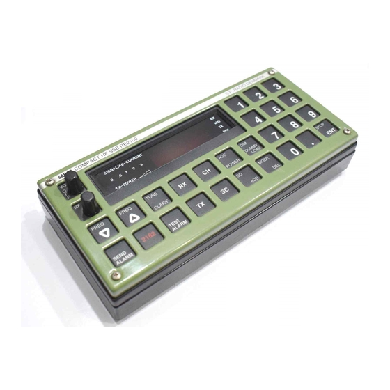
Sailor RE2100 Instruction Book (219 pages)
Brand:
Sailor
| Category:
Transceiver
| Size: 53.53 MB
Table of Contents
Contents
2
Introduction
5
General Description
6
Technical Data
7
Controls
9
Principle of Operation
11
Processor Unit
11
Display Unit
11
Synthesizer Unit
11
Exciter Unit
12
Power Unit
12
Installation
17
Mounting Possibilities
17
Tabletop and Deckhead
17
Bulkhead and Console
18
Dimensions and Drilling Plan
19
Electrical Connection and Assembling
25
Service
29
Maintenance
29
Preventive Maintenance
29
Alignment
29
Proposal for Necessary Test Equipment
30
Diode Probe
31
Layout of the Probe
31
Power Supply
32
Testbox
32
Component Location Testbox
32
Diagram Testbox
33
Troubleshooting
35
Locating the Fault Unit
35
Error Codes
36
Locating the Fault Module
37
Locating the Faulty Circuit
37
Performance Check
38
General
38
Performance Check of Display and Keyboard
39
Performance Check of Display
39
Performance Check of Receiver
41
Performance Check of Receiver Sensitivity
41
SSB Mode
42
AM Mode
42
Performance Check of Receiver Audio Passband
43
LSB-SSB Mode
43
Performance Check of Receiver AGC
45
SSB Decay
47
AM Attach and Decay
47
Performance Check of Receiver Squelch
48
Performance Check of Receiver External Connections
48
Performance Check of Exciter
50
Performance Check of Exciter Output Signal
50
Performance Check of Exciter Step Attenuator
53
Module Performance Check
55
Module Performance Check of Receiver Unit
56
Check of Sensitivity
56
Check of LO2 and Reinjection Signals
57
Check of Crystal Filters
57
Check of Detector
63
Check of AF Fitlers
64
Check of Earpiece Amplifier
65
Check of Squelch Circuit
66
Module Performance Check of Front End Unit
68
Check of Front End Gain
69
Check of Mute and RX/TX Switch
71
Check of Selection Circuit for Pre-Filters
72
Check of LO1 Signal and Buffer
72
Check of TCXO
73
Check of PLL1
73
Check of PLL2
74
Check of Compressor and AF Limiter
76
Check of Carrier Limiter Amplifier
77
Check of Modulator
77
Check of RF Limiter and Carrier Insertion
77
Check of Step Attenuator
78
Check of 70Mhz if and lo Injection
78
Check of on Board Power Supply
79
Check of Microprocessor
79
Check of External ROM
79
Control of Power Low Circuit
80
Control of Watch Dog Circuit
80
Check of Baud Rate Generator
80
Check of Tune/Alarm Tone Generator
80
Control of Tune Tone
81
Control of Alarm Tone
81
Check of Distress Driver
81
Check of Meter Amplifier
81
Check of SPI Data
82
Check of SPI Clock
82
Check of SPI Address Select
82
Check of SP-BUS Transmitter/Receiver
83
Check of EEPROM U05
83
Module Performance Check of Power Unit
85
Check of Voltage Regulators
85
Check of RF Amplifier and Filter
85
Adjustment Procedure
87
Adjustment Procedure for Front End and Receiver Unit
87
Adjustment of 70 Mhz Transformer
88
Adjustment of 2Nd if Gain
88
Adjustment of Signal Meter
89
Adjustment of Earpiece Level
89
Adjustment Procedure for Synthesizer Unit
90
Adjustment of TCXO
90
Adjustment of the VCO Circuits in PLL1
90
Adjustment of the VCO Circuits in PLL2
91
Adjustment Procedure for Exciter Unit
92
Adjustment of Compressor and AF Limiter
92
Adjustment of Carrier Limit Amplifier
92
Adjustment of Modulator
93
Adjustment of RF Limiter
93
Adjustment of Carrier Insertion
93
Adjustment of Step Attenuator
94
Adjustment of 70 Mhz if
95
Adjustment for Power Unit
96
Adjustment of +5V
96
Adjustment of RF Output Level
96
Necessary Adjustment and Check after Repair
97
Receiver Unit
97
Front End Unit
98
Function Check
100
Selection and Description of the Service Programmes
102
How to Select a Service Program
102
Description of Service Programmers
102
Mechanical Disassembling and Module Location
109
Circuit Description and Schematic Diagrams
115
Second Mixer and Crystal Filters
115
IF Amplifier
115
AGC Generator
115
Detector
116
AF Switches
118
Block Diagram of AF Switches
118
AF Output Amplifiers
118
AF Pre. Amplifier
118
Squelch
119
Earpiece Amplifier
119
Limiting Amplifier
119
Voltage Change Detector
119
Signal Strength Detector
120
Microprocessor Controlling
120
Logarithmic Amplifier
120
Buffer Amplifier
120
Phase Locked Loop 1
135
Voltage Controlled Oscillators
135
Passive Loop Filter
136
Active Loop Filter
136
Phase Detector
136
Current Mirror
137
Control Signal Outs
137
API Circuit
137
Modulus Control Logic
138
Divider Circuits
138
Buffer Circuits
138
Phase Locked Loop 2
139
USB Receiver
139
LSD Receiver
139
Prescaler Buffer
141
Prescaler and Divider
141
Phase Detector and Loop Filter
141
Output Local Oscillator Buffer
141
AF Selector
149
Compressor and AF Limiter
149
Carrier Limiter Amplifier
149
Modulator
149
Modulation Level Amplifier
150
Carrier Level Amplifier
150
Mode Selector
150
Step Attenuator and 1St Mixer
150
Microprocessor
157
Watch Dog
157
Memory
157
Keyboard
157
Ext. Port
158
On Board Power Supply
158
Tune/Alarm Tone Generator
158
Distress Driver
158
SP-BUS Transmitter and Receiver
159
Component Location Processor Unit
160
Display Driver
167
Dummy Load and Tune Led
167
Keyboard Light Driver
167
LED-Bar and LED-Bar Driver
167
Regulators
173
RF Amplifier and Filter
173
Component Location Power Unit
174
Interconnection Cable Plan
177
Microtelephone Installation
181
Advertisement
Sailor RE2100 Technical Manual (186 pages)
Compact HF SSB
Brand:
Sailor
| Category:
Radio
| Size: 11.69 MB
Table of Contents
Table of Contents
5
1 General Information
7
Introduction
7
Description of Sailor Hf Ssb Programme
7
General Description of Sailor Hf Ssb Re2100
10
Technical Data
11
(Complies with SOLAS, ITU, CEPT, MPT, DOC, FTZ, KSR, FCC)
11
Controls
13
Principle of Operation
15
2 Installation
19
Mounting Possibilities
19
Dimensions and Drilling Plan
19
Electrical Connection and Assembling
19
Installation 2.1 Mounting Possibilities
21
3 Service
29
Maintenance
29
Alignment Instructions
29
Proposal for Necessary Test Equipment
29
Trouble Shooting
29
Performance Check
29
Module Performance Check
29
Adjustment Procedure
29
Necessary Adjustment and Check after Repair
29
Function Check
29
Service 3.1 Maintenance
31
Performance Check of Display and Keyboard
39
Performance Check of Receiver
41
Performance Check of Exciter
48
Module Performance Check of Receiver Unit
52
Module Performance Check of Front End Unit
62
Module Performance Check of Synthesizer Unit
67
Module Performance Check of Exciter Unit
70
Performance Check of Microprocessor Module
72
Adjustment Procedure for Front End and Receiver Unit
77
Module Performance Check of Power Unit
77
Adjustment Procedure for Synthesizer Unit
80
Adjustment Procedure for Exciter Unit
82
Adjustment Procedure for Power Unit
85
Description of Service Programmes
90
How to Select a Service Programme
90
Selection and Description of the Service Programmes
90
4 Mechanical Disassembling and Module Location
93
Adjustments and Locations
93
5 Circuit Description and Schematic Diagrams
99
Receiver Unit (Module 1) Part No. 625631
101
Circuit Description and Schematic Diagrams 5.1 Receiver Unit (Module 1) Part No. 625631
101
Front End Unit (Module 2) Part No. 625632
109
Synthesizer Unit (Module 3) Part No. 625633
113
Exciter Unit (Module 4) Part No. 625634
123
Processor Unit (Module 5) Part No. 625635
129
Keyboard Unit (Module 6) Part No. 625636
135
Display Unit (Module 7) Part No. 625637
137
Power Unit (Module 8) Part No. 625638
141
Interconnection Cable Plan
145
6 Microtelephone Installation
147
Normal Installation Re2100 and C2140
147
Normal Installation Re2100 or C2140 with 2 Micro Telephones
147
Mechanical Dimensions for Handset
147
Microtelephone Installation 6.1 Normal Installation Re2100 and C2140
151
7 Parts List
155
Advertisement
Related Products
Sailor RT2047
Sailor RM2042
Sailor R109
Sailor R108
Sailor RT2047D
Sailor SA-S RED240
Sailor RT5020 VHF DSC Duplex
Sailor R 110
Sailor R 103
Sailor R 105
Sailor Categories
Radio
Transceiver
Marine Equipment
Receiver
Marine Radio
More Sailor Manuals
Login
Sign In
OR
Sign in with Facebook
Sign in with Google
Upload manual
Upload from disk
Upload from URL