Sign In
Upload
Manuals
Brands
S&P Manuals
Air Handlers
UTBS-2
S&P UTBS-2 Manuals
Manuals and User Guides for S&P UTBS-2. We have
4
S&P UTBS-2 manuals available for free PDF download: Installation Manual. Instructions For Use, Installation Manual, Manual
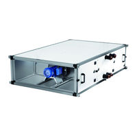
S&P UTBS-2 Installation Manual (90 pages)
Low-profile air-handling units
Brand:
S&P
| Category:
Air Handlers
| Size: 3 MB
Table of Contents
Español
2
Table of Contents
2
Generalidades
3
Normas de Seguridad y Marcado "Ce
3
Normas Generales
3
Etiquetado de la Unidad
4
Manipulación
5
Instalación
5
Generalidades
5
Identificación de Partes del Equipo
6
Lugar de Emplazamiento
6
Espacio para Mantenimiento
6
Ensamblaje de Módulos
8
Unión de Tejadillos
8
Ensamblaje de Juntas Flexibles
9
Ensamblaje de Unidades en Paralelo
9
Conexión Eléctrica del Equipo
10
Conexión de la Batería Eléctrica
11
Conexión de Los Motores
11
Conexión de Sensores de Presión
16
Ensuciamiento de Filtros
16
Control en Ventiladores
16
Conexionado del Equipo a Presión O Caudal Constante
16
Configuración del Transmisor de Presión Diferencial
17
(Tdp-S y Tdp-D)
17
Modelo Tdp-S
18
Modelo Tdp-D
19
Calibración del Transmisor de Presión (Tdp-S y Tdp-D)
21
Configuración del Variador de Frecuencia
21
Ajuste del Punto de Trabajo
21
Funcionamiento y Fallos
22
Reconfiguración del Variador de Frecuencia
23
Conexión del Equipo a la Red Hidráulica
25
Conexión del Equipo a la Red de Conductos
26
Red de Desagüe
26
Procedimiento de Puesta en Marcha
27
Instalación de Cajas con Compuertas
27
Operaciones de Emergencia
28
Mantenimiento Preventivo
29
Baterías de Intercambio Térmico
29
Red de Desagüe
29
Motores
29
Ventiladores
30
Filtros
30
Sustitución de Filtro en Equipo Principaly Recuperador Paralelo y de Doble Altura
30
Baterías
31
Compuertas
31
Sustitución de Filtros en Recuperadores en Línea
31
Módulo de Mezclas
32
Caja de Mezcla 2 Vías con Bancada y Tejadillo
33
Humectador
33
Recuperador
34
Reciclaje
34
English
35
General Standards
36
Overview
36
Safety Standards and "Ec" Marking
36
Handling
37
Unit Labeling
37
Identification of Parts of the Unit
38
Installation
38
Overview
38
Installation Site
39
Maintenance Space
39
Assembling Flexible Connections
41
Assembling the Modules
41
Cover Seams
41
Assembling Units Side by Side
42
Electrical Connection
43
Connecting the Electrical Heater
44
Connecting the Motors
44
Connecting the Constant Pressure or Constant Airflow Equipment
49
Connecting the Pressure Sensors
49
Dirty Filters
49
Fan Controls
49
(Tdp-S & Tdp-D)
50
Configuring the Differential Pressure Transmitter
50
Tdp-S Model
51
Tdp-D Model
52
(TDP-S and TDP-D)
54
Calibration of the Pressure Transmitter
54
Configuring the Variable Frequency Drive
54
Setting the Working Point
54
Operation and Faults
55
Reconfiguring the Frequency Inverter
56
Connecting the Unit to the Water Network
58
Connecting the Unit to the Duct System
59
Drainage System
59
Installing Dampers Boxes
60
Start-Up Procedure
60
Emergency Operations
61
Preventive Maintenance
61
Drainage System
62
DX Coils
62
Heat Exchanger Coils
62
Motors
62
Filters
63
Replacing the Filter in the Main Unit and Side-By-Side or Stacked Recovery Unit
63
Ventiladores
63
Coils
64
Dampers
64
Replacing Filters for In-Line Recovery Modules
64
Mixing Module
65
Silencer
65
Mixing Box 2 Way with Base and Roof
66
Recovery Unit
66
Recycling
67
Français
68
Généralités
69
Normes de Sécurité Et Marquage "Ce
69
Normes Générales
69
Étiquetage de L'unité
70
Généralités
71
Installation
71
Manipulation
71
Emplacement
72
Espace Pour la Maintenance
72
Identification des Composants
72
Assemblage des Modules
74
Montage des Manchettes Souples
74
Toles Pare-Pluie
74
Assemblage D'appareils en Parallèle
75
Raccordement Aux Moteurs
76
Raccordement Électrique
76
Raccordement de la Batterie Électrique
77
Branchement des Capteurs de Pression
80
Contrôle Sur Les Ventilateurs
80
Filtres Encrasses
80
Raccordement de L'équipement Au Réseau de Conduits
82
Reseau D'evacuation
82
Installation de Caissons de Melange
83
Mise en Marche
83
Maintenance Préventive
84
Opérations D'urgence
84
Batteries D'échange Thermique
85
Filtres
85
Moteurs
85
Réseau D'évacuation
85
Ventilateurs
85
Remplacement des Filtres Sur Les Récupérateurs en Ligne
86
Remplacement du Filtre du Module Principal Et des Modules Avec Récupérateur de Chaleur
86
Batteries
87
Humidificateur
87
Registres
87
Récupérateur
88
Recyclage
89
Advertisement
S&P UTBS-2 Installation Manual. Instructions For Use (112 pages)
Low-profile air-handling units
Brand:
S&P
| Category:
Air Handlers
| Size: 3 MB
Table of Contents
English
39
Table of Contents
39
1 Overview
40
Safety Standards and "Ec" Marking
40
3 General Standards
40
4 Unit Labeling
41
5 Handling
41
6 Installation
42
Overview
42
Identification of Parts of the Unit
42
Installation Site
43
Maintenance Space
43
Assembling the Modules
45
Cover Seams
45
Assembling Flexible Connections
45
Assembling Units Side by Side
46
Electrical Connection
47
Connecting the Motors
48
Connecting the Electrical Heater
49
Connecting the Pressure Sensors
55
Dirty Filters
55
Fan Controls
55
Connecting the Constant Pressure or
55
Constant Airflow Equipment
55
Configuring the Differential Pressure Transmitter
56
(Tdp-S & Tdp-D)
56
Tdp-S Model
57
Tdp-D Model
58
Calibration of the Pressure Transmitter
60
(TDP-S and TDP-D)
60
Configuring the Variable Frequency Drive
60
Setting the Working Point
60
Operation and Faults
61
Reconfiguring the Frequency Inverter
61
Connecting the Unit to the Water Network
63
Connecting the Unit to the Duct System
65
Batteries Direct Expansion
65
Drainage System
66
Installing Dampers Boxes
66
7 Start-Up Procedure
67
8 Emergency Operations
68
9 Preventive Maintenance
68
DX Coils
69
Drainage System
69
Motors
69
Filters
69
Replacin-Lineg the Filters In-Line the Main-Line Unit and Side-By-Side for Stacked Recovery Unit
70
Coils
71
Dampers
71
Silencer
71
Mixing Module
72
Mixing Box 2 Way with Base and Roof
72
Recovery Unit
73
10 Recycling
73
Français
74
1 Généralités
75
2 Normes de Sécurité Et Marquage "Ce
75
3 Normas Generales
75
4 Étiquetage de L'unité
76
5 Manipulation
77
6 Installation
77
Identification des Composants
78
Emplacement
78
Espace Necessaire a la Maintenance
78
Assemblage des Modules
80
Toles Pare-Pluie
80
Montage des Manchettes Souples
81
Assemblage D'appareils en Parallèle
81
Raccordement Électrique
82
Raccordement des Moteurs
83
Raccordement de la Batterie Électrique
84
Branchement des Capteurs de Pression
90
Filtres Encrasses
90
Contrôle Sur Les Ventilateurs
90
Raccordement de L'unité en Pression Constante Ou en Débit Constant
90
Configuration du Transmetteur de Pression Différentielle
91
(TDP-S Et TDP-D)
91
Modèle Tdp-S
91
Modèle Tdp-D
93
CALIBRATION du TRANSMETTEUR de PRESSION (TDP-S Et TDP-D)
95
Configuration du Variateur de Fréquence
95
Réglage du Point du Fonctionnement
95
Fonctionnement Et Défauts
96
Réinitialisation du Variateur de Fréquence
96
Raccordement de L'unite Au Réseau D'eau
98
Raccordement de L'équipement Au Réseau de Conduits
100
Batteries DX
101
Reseau D'evacuation
101
Installation de Caissons de Mélange
101
7 Mise en Marche
102
8 Opérations D'urgence
103
9 Maintenance Préventive
103
Batteries D'échange Thermique
103
Réseau D'évacuation
104
Moteurs
104
Ventilateurs
104
Filtres
104
Remplacement du Filtre du Module Principal Et des Modules Avec Récupérateur de Chaleur
105
Remplacement des Filtres Sur Les Récupérateurs en Ligne
105
Batteries
106
Registres
106
Silencieux
106
Caissons de Mélange
107
Caisson de Mélange Avec Chassis Et Tole Pare-Pluie
107
Humidificateur
108
Récupérateur
109
10 Recyclage
109
S&P UTBS-2 Manual (72 pages)
Brand:
S&P
| Category:
Air Handlers
| Size: 5 MB
Table of Contents
Table of Contents
3
1 Overview
5
Safety Standards and "Ec" Marking
5
2 Safety Standards and “Ec” Marking
5
3 General Standards
5
4 Unit Labeling
6
5 Technical Characteristics
6
6 Handling
9
7 Installation
10
Overview
10
Identifi Cation Unit Parts
11
Installation Site
11
Maintenance Space
11
Dimensions
12
Space for Maintenance
15
Assembling the Modules
17
Additional Filters Mounting
18
Assembling Flexible Connections
18
Mixing Module Installation
19
Installation with Isolation Damper
19
Connecting the Unit to the Duct System
21
Direct Expansion Coils Connection (DX)
22
Drainage System
23
Electrical Connection
23
Temperature Probes Location
24
8 Start-Up Procedure
26
9 Control Functions
27
10 Control Diagram
29
11 Remote Control Operation
32
Change Language
32
Simplified Menus / Accesses
32
User Level
32
Installer Level
33
Operation Fan Modes
35
Constant Airfl Ow Operation (CAV)
35
Variable Airfl Ow Operation (VAV)
37
Constant Pressure Operation (COP)
38
Control Slave of an External Fan (for All Working Modes)
41
Postheater Control
42
Constant Supply Air Temperature Maintenance
42
Constant Ambient Temperature Maintenance
42
Temperature Set Point Adaptation Vs. Outdoor Temperature
43
Automatic Control Mode
43
Initial Temperature Setpoint
43
Time Programming
44
Mixing Module Control (3 Ways)
47
Without Mixing Module
47
CO Control
47
Temperature Control
47
CO Control and Temperature
47
Control of Isolation Damper
47
12 BOOST FUNCTION (Only Available in CAV and COP Modes)
48
13 Remote Stop-Start
48
14 Free Cooling by Night
49
15 Water Heater Frost Protection
50
16 Reset the Corrigo Controller
50
17 Connection to Building Management Systems (Bms)
53
RTU Modbus
53
TCP/IP Bacnet
54
18 Replacement of the Battery from the Corrigo Programmable Logic Controller
54
19 Operation Anomalies
55
General Anomalies
55
Failure List
56
20 Emergency Operations
57
21 Preventive Maintenance
57
Water Coils
58
DX Coils
58
Drainage System
58
Motors
58
Fans
58
Filters
58
Replacing the Filter in the Main Unit and Side-By-Side or Stacked Recovery Unit
59
Replacing Filters for In-Line Recovery Modules
60
Coils
60
Dampers
60
Silencers
61
Connecting the Unit to the Water Network
61
22 Wiring Diagrams
62
Advertisement
S&P UTBS-2 Manual (52 pages)
Brand:
S&P
| Category:
Air Handlers
| Size: 6 MB
Table of Contents
Table of Contents
2
Introduction
4
Safety Regulations and "Ce" Marking
4
General Instructions
4
Unit Labelling
5
Handling
5
Technical Characteristics
6
Installation
9
Overview
9
Identification Unit Parts
10
Installation Site
10
Maintenance Space
10
Dimensions
11
Space for Maintenance
27
Assembling the Modules
29
Move the Fl Ange from the Main Module to the Accessory Module
30
Additional Fi Lters Mounting
31
Assembling Fl Exible Connections
31
Mixing Module Installation
31
Installation with Isolation Damper
32
Connecting the Unit to the Hidraulic Circuit
32
Connecting the Unit to the Duct System
34
Direct Expansion Coils Connection (DX)
34
Drainage System
37
Outdoor Installation
37
Electrical Connection
38
Connecting the Motors
39
Electric Battery Connection
40
Pressure Switches Connection
44
Filter Clogging Detection
44
Fan Control
44
Start-Up Procedure
45
Operation Anomalies
46
General Anomalies
46
Emergency Operations
47
Preventive Maintenance
47
Water Coils
48
DX Coils
48
Drainage System
48
Motors
48
Fans
48
Filters
48
Filter Replacement
49
Coils
51
Dampers
51
Advertisement
Related Products
S&P UTBS PRO-REG Series
S&P UTBS-3
S&P UTBS-5
S&P UTBS-8
S&P UTBS Series
S&P UTBS-3 1,1kW
S&P UTBS-5 1,1kW
S&P UTBS-5 2,2kW
S&P UTBS-8 1,5kW
S&P UTBS-8 3kW
S&P Categories
Fan
Heater
Ventilation Hood
Controller
Heating System
More S&P Manuals
Login
Sign In
OR
Sign in with Facebook
Sign in with Google
Upload manual
Upload from disk
Upload from URL