Sign In
Upload
Manuals
Brands
Rosemount Manuals
Measuring Instruments
951C
Rosemount 951C Manuals
Manuals and User Guides for Rosemount 951C. We have
3
Rosemount 951C manuals available for free PDF download: Instruction Manual
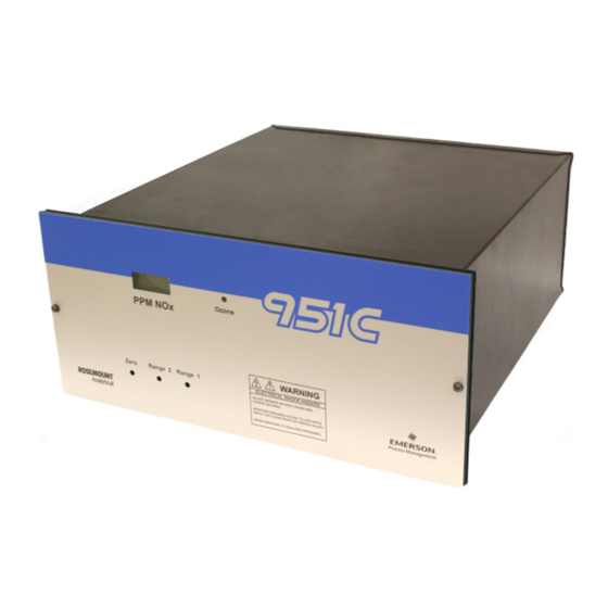
Rosemount 951C Instruction Manual (90 pages)
NOx Analyzer
Brand:
Rosemount
| Category:
Measuring Instruments
| Size: 3 MB
Table of Contents
Table of Contents
3
Section 1: Description and Specifications
15
Typical Applications
16
Specifications
17
Section 2: Installation
19
Unpacking
19
Location
19
Voltage Requirements
20
Operating on 230 VAC
20
Connecting Cables
22
Connecting the Power Cord
23
Connecting the Potentiometric Recorder Cables
24
Connecting the Current Recorder
24
Adjusting the Current Output to Produce a Zero of 0 Ma
24
Gas Requirements
25
Air (U.S.P. Breathing Grade)
25
Span Gas
25
Sample Requirements
26
Connecting Gas
27
Leak Testing
28
Section 3: Operation
29
Front Panel Indicators and Controls
29
Display
29
Range Selection
29
Blinking Backlight
30
Sample Pressure Gauge
31
Ozone Pressure
31
Zero and Span Potentiometers
32
Ozone Interlock
32
Starting the Analyzer
34
Setting up Remote Range Switching
37
Calibrating the Analyzer
40
Zero Calibrating
40
Upscale Calibrating
40
Optimizing the Converter Temperature
41
Measuring Converter Efficiency
44
Recommended Calibration Frequency
45
Section 4: Theory
47
Nitric Oxide Concentration Is Determination by Chemiluminescence Method
47
Analyzer Flow System
47
Flow of Sample, Standard Gas or Zero Gas to Reaction Chamber
50
Ozone Generation
50
Signal Conditioning and Display
51
Circuit Functions
52
Analyzer Thermal System
54
Section 5: Routine Servicing
57
System Checks and Adjustments
57
Adjusting the Display Fullscale Span
57
Factors Affecting the Overall Sensitivity of the Analyzer
58
Monitoring Ozone Output
59
Finding the Cause of Excessive Background Current
60
Servicing the Flow System
61
Cleaning the Sample Capillary
61
Confirming a Faulty Ozone Restrictor Fitting
63
Servicing the Photomultiplier Tube and the Reaction Chamber
65
Removing or Replacing the Photomultiplier Assembly
67
Cleaning the Reaction Chamber
67
Reconstructing the Photomultiplier Assembly
71
Photomultiplier Tube and Housing
72
Replacing the Photomultiplier Tube
72
Ozone Generator Assembly
73
Removing the Ultraviolet Lamp and Lamp Housing
73
Replacing the Ultraviolet Lamp
74
Removing the Power Supply
74
Converter Assembly
75
Removing the Glass Converter Tube
76
Servicing the Electronic Circuitry
76
Section 6: Replacement Parts
77
Matrix
77
Circuit Board Replacement Policy
78
Replacement Parts
78
Common Parts
79
Photomultiplier Assembly
81
Converter Assembly 654070
83
Temperature Control Assembly 654068
84
Advertisement
Rosemount 951C Instruction Manual (60 pages)
NOx Analyzer
Brand:
Rosemount
| Category:
Measuring Instruments
| Size: 3 MB
Table of Contents
Table of Contents
3
Preface
7
Definitions
7
Safety Summary
8
General Precautions for Handling and Storing High Pressure Gas Cylinders
11
Documentation
12
Compliances
12
Condensed Startup and Calibration Procedure
13
Description and Specifications
15
Overview
15
Typical Applications
15
Specifications
16
Installation
17
Unpacking
17
Location
17
Voltage Requirements
17
Electrical Connections
17
Line Power Connections
17
Figure 2-1. Power Supply Board Voltage Select Switches
18
Figure 2-2. Temperature Control Board
18
Potentiometric Recorder Connections
19
Current Recorder Connections
19
Figure 2-3. Cable Gland
19
Figure 2-4. Rear View of Model 951C (Cover Removed)
19
Figure 2-5. Rear Panel Wiring Connections
20
Gas Requirements
21
Air (U.S.P. Breathing Grade)
21
Span Gas
21
Sample Requirements
21
Gas Connections
21
Leak Test
22
Operation
23
Front Panel Indicators and Controls
23
Display
23
Range Selection
23
Sample Pressure Gauge
23
Ozone Pressure
23
Figure 3-1. Model 951C Controls, Indicators and Adjustments
23
Zero and Span Potentiometers
24
Ozone Interlock
24
Figure 3-2. Signal Board
24
Figure 3-3. Signal Board Test Points
24
Figure 3-4. Signal Board Diagnostic Jumpers
24
Figure 3-5. Hi/Lo Range Select Jumper
25
Figure 3-6. PPM Range Select Switch
25
Figure 3-7. Decimal Point Select Jumpers
25
Figure 3-8. Range 2 Selection Jumpers
25
Startup Procedure
25
Figure 3-9. Power Supply Board
27
Calibration
28
Zero Calibration
28
Upscale Calibration
28
Routine Operation
28
Converter Temperature Adjustment Procedure
28
Table 3-1. Resistance of Converter Temperature Sensor Vs. Temperature
29
Measurement of Converter Efficiency
30
Recommended Calibration Frequency
30
Theory
31
Nitric Oxide Determination by Chemiluminescence Method
31
Analyzer Flow System
31
Flow of Sample, Standard Gas or Zero Gas to Reaction Chamber
31
Ozone Generation
31
Signal Conditioning and Display
32
Circuit Functions
32
Analyzer Thermal System
33
Figure 4-1. Analyzer Signal Conditioning Circuit
34
Figure 4-2. Analyzer Thermal System
35
Routine Servicing
37
System Checks and Adjustments
37
Display Fullscale Span Adjustment
37
Overall Sensitivity
37
Ozone Output
38
Background Current
38
Servicing Flow System
38
Cleaning Sample Capillary
39
Ozone Restrictor Fitting
39
Photomultiplier Tube/Reaction Chamber
39
Removal
40
Cleaning Reaction Chamber
40
Photomultiplier Tube and Housing
41
Replacement of Photomultiplier Tube
41
Ozone Generation System
42
Lamp/Housing Removal
42
UV Lamp Replacement
42
Power Supply Removal
43
Converter Assembly
43
Servicing Electronic Circuitry
43
Replacement Parts
45
Matrix
45
Circuit Board Replacement Policy
46
Replacement Parts
46
Common Parts
46
Figure 6-1. Major Assemblies of the Model 951C
47
Figure 6-2. Photomultiplier Housing Assembly
48
B. Photomultiplier Assembly 654062
48
Converter Assembly 654070
49
Figure 6-3. Converter Assembly
49
Temperature Control Assembly 654068
50
Figure 6-4. Case Heater Temperature Control Assembly
50
Return of Material
51
Customer Service
51
Training
51
Index
53
Rosemount 951C Instruction Manual (58 pages)
NOX ANALYZER
Brand:
Rosemount
| Category:
Measuring Instruments
| Size: 0 MB
Table of Contents
Table of Contents
3
Preface
7
Purpose/Safety Summary
7
Specifications - lo Range
10
Specifications - Hi Range
11
Customer Service, Technical Assistance and Field Service
12
Returning Parts to the Factory
12
Training
12
Documentation
12
Compliances
13
Condensed Startup and Calibration Procedure
16
Introduction
17
Overview
17
Applications
18
Installation
19
Location
19
Unpacking
19
Voltage Requirements
19
Electrical Connections
20
Line Power Connections
20
Figures
21
Power Supply Board Voltage Select Switches
21
Temperature Control Board
21
Potentiometric Recorder Connections
22
Current Recorder Connections
22
Cable Gland
22
Gas Requirements
23
Rear View of Model 951C
23
Gas Connections
24
Sample Requirements
24
Leak Test
25
Initial Tartup and
27
Front Panel Indicators and Controls
27
Display
27
Range Selection
27
Model 951C Controls, Indicators and Adjustments
27
Sample Pressure Gauge
28
Ozone Pressure
28
Zero and Span Potentiometers
28
Ozone Interlock
28
Startup Procedure
29
Signal Board
30
Power Supply Board
31
Calibration
32
Zero Calibration
32
Upscale Calibration
32
Routine Operation
32
Converter Temperature Adjustment Procedure
33
Measurement of Converter Efficiency
35
Recommended Calibration Frequency
36
Nitric Oxide Determination by Chemiluminescence
37
Method
37
Analyzer Flow System
37
Chamber
37
Ozone Generation
38
Signal Processing Electronics System
38
Analyzer Thermal System
39
Analyzer Signal Conditioning Circuit
39
Analyzer Thermal System
40
Routine Servicing
41
System Checks and Adjustments
41
Display Fullscale Span Adjustment
41
Overall Sensitivity
42
Ozone Output
42
Background Current
43
Excessive Photomultiplier Dark Current
43
Servicing Flow System
44
Cleaning Sample Capillary
44
Ozone Restrictor Fitting
45
Photomultiplier Tube/Reaction Chamber
46
Photomultiplier Tube/Reaction Chamber Removal
46
Cleaning Reaction Chamber
46
Photomultiplier Tube and Housing
48
Replacement of Photomultiplier Tube
48
Ozone Generation System
49
Lamp/Housing Removal
49
UV Lamp Replacement
50
Power Supply Removal
50
Converter Assembly
51
Servicing Electronic Circuitry
51
Replacement
53
Circuit Board Replacement Policy
53
Replacement Parts
53
Major Assemblies of the Model 951C
55
Photomultiplier Housing Assembly
56
Converter Assembly
57
Case Heater Temperature Control Assembly
58
Advertisement
Advertisement
Related Products
Rosemount 1054A pH
Rosemount 1054B
Rosemount 1151
Rosemount 1151AP
Rosemount 1151DP
Rosemount 1151GP
Rosemount 1151HP
Rosemount 1151LT
Rosemount 1159
Rosemount 1195
Rosemount Categories
Measuring Instruments
Transmitter
Accessories
Analytical Instruments
Touch Panel
More Rosemount Manuals
Login
Sign In
OR
Sign in with Facebook
Sign in with Google
Upload manual
Upload from disk
Upload from URL