Sign In
Upload
Manuals
Brands
Rohde & Schwarz Manuals
Measuring Instruments
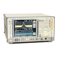
FSEB30
Rohde & Schwarz FSEB30 Manuals
Manuals and User Guides for Rohde & Schwarz FSEB30. We have
2
Rohde & Schwarz FSEB30 manuals available for free PDF download: Operating Manual, Operating Instructions Manual
Rohde & Schwarz FSEB30 Operating Instructions Manual (421 pages)
SPECTRUM ANALYZER
Brand:
Rohde & Schwarz
| Category:
Test Equipment
| Size: 4 MB
Table of Contents
Tabbed Divider Overview
3
Safety Instructions
5
Patent Information
6
Support Center
13
Table of Contents
21
Preparing for Operation
23
Description of Front and Rear Panel Views
23
Front View
23
Rear View
35
Start-Up - Instruments with Windows NT ® Controller
40
Unpacking the Instrument
40
Setting up the Instrument
40
Stand-Alone Operation
40
19" Rack Installation
41
EMI Protection Measures
41
Connecting to AC Supply
41
AC Power Line Fuses
41
Switching the Instrument On/Off
42
Switching on the Instrument
42
Startup Menu and Booting
43
Switching off the Instrument
43
Energy Saving Mode
43
Battery Backed-Up Memory
43
Function Test
44
Controller Function - Windows NT
45
Connecting a Mouse
46
Connecting an External Keyboard
47
Connecting an External Monitor
48
Connecting a Printer
50
Installation of a Network Printer (with Option FSE-B16 Only)
56
Connecting a CD-ROM Drive
58
Firmware Update
60
Installing Windows NT Software
61
Options
62
Option FSE-B17 - Second IEC/IEEE Interface
62
Installing the Software
62
Operation
64
Option FSE-B5 - FFT Filter
65
Option FSE-B16 - Ethernet Adapter
66
Hardware Installation
66
Software Installation
67
Examples of Configurations
71
Operation
71
Printing on a Network Printer
74
Server Function
76
Start-Up - Instruments with MS DOS ® Controller or Without Controller
78
Unpacking the Instrument
78
Instrument Setup
78
19" Rack Installation
78
EMI Protection Measures
79
Connecting to AC Power
79
AC Power Line Fuses
79
Instrument On/Off
79
Battery-Powered Memory
80
Functional Test
80
Connecting a Mouse
80
Connecting an External Keyboard
84
Connecting an Output Device
88
Firmware Update
92
Options
93
Option FSE-B17 - Second IEC/IEEE Interface
93
Installing the Software
93
Operation
93
Option FSE-B5 - FFT Filter
94
Prerequisites
94
Enabling the Option
94
Option FSE-B16 - Ethernet Adapter
95
Hardware Installation
95
BNC (Thin Ethernet, Cheapernet; FSE-B16 Var. 03)
95
AUI (Thick Ethernet; FSE B16 Var. 02)
96
RJ45 (UTP, 10Baset, Western Connector)
96
Software Installation
97
Installation of Network Drivers
97
Installation of Network Operating System
100
Novell Netware
100
Operation
103
Getting Started
113
Level and Frequency Measurements
113
Measurement Task
113
Important Spectrum Analyzer Functions
114
Sweep, Level and Frequency Measurements - Example 1
114
Center Frequency
114
Sweep, Level and Frequency Measurements - Example 2
118
Level Measurement Accuracy
120
Measurement of Harmonic Separation
121
Measurement Task
121
Important Spectrum Analyzer Functions
122
Measurement Procedure - Harmonic Separation - Example 1
123
Reference Level
123
Start Frequency
124
Stop Frequency
124
Measurement Procedure - Harmonic Separation - Example 2
128
Measurement Procedure - Harmonic Separation - Example 3
132
Measurement of Intermodulation Distortions
136
Measuring Task
136
Important Spectrum-Analyzer Functions
137
Measurement
138
Reference Level
139
Input Attenuation
140
Time-Domain Measurements with Pulsed Signals
143
Measuring Task
143
Important Spectrum Analyzer Functions
143
Measurement
144
Sweep Time
145
Gap Length
148
Manual Operation
153
The Screen
154
Diagram Area
155
Displays in the Diagram Area
156
Full Screen
161
Split Screen
161
Softkey Area
162
Changing the Menu
163
Setting the Parameters
165
Data Entry
165
Numeric Keypad on the Front Panel
165
Roll-Key and Cursor Keys
166
Entry Windows
167
Setting up the Entry Window
167
Editing of Numeric Parameters
168
Editing of Alphanumeric Parameters
169
Help Line Editor
169
Shifting Mode
170
Editing Mode
170
Disabling the Control Elements - HOLD Key
171
Setting the Stepsize - STEP Key
172
Mouse and External Keyboard Control
173
External Keyboard Control
173
Data Entry Windows with Mouse Control
174
Mouse Control of Further Display Elements
175
Menu Overview
176
System Key Group
176
Display Info
176
Configuration Key Group
179
Setup for Instruments with Windows NT Controller Option
180
Setup for Instruments with MS DOS Controller Option or Without Controller
181
Hardcopy Key Group
182
Frequency Key Group
183
Level Key Group, Input Key
184
Marker Key Group
186
Normal Search
187
Lines Key Group
190
Trace Key Group
192
Sweep Key Group
193
Memory Key Group
195
User Key Group
198
Instrument Functions
203
General Configuration - SYSTEM and CONFIGURATION Key Groups
204
FSE Initial Configuration - PRESET Key
204
Display Configuration - DISPLAY Key
205
Display Screen Mode Selection
206
Measurement Window Coupling
207
Display Screen Configuration
208
Recording the Correction Data - CAL Key
211
Correction Function Calls
212
Results of System Error Correction
214
Calibration Results
214
Instrument Status and Measurement Parameters - INFO Key
215
Firmware Versions
215
Hardware Configuration and Options
216
Self Test
217
System Messages
218
Statistics Function for Input Attenuator Switching
219
Mode Selection - MODE Key
220
Preliminary Setup and Interface Configuration - SETUP Key
222
Using Transducers
222
Activating Transducer Factors and Transducer Sets
223
Transducer Set
224
New Entry and Editing of Transducer Factors
225
New Entry and Editing of Transducer Sets
229
Enabling Firmware Options
233
External Reference Oscillator
233
Service Functions
234
Setting the Interface Configuration and Time - with Windows NT Controller
236
User Port Configuration
237
Setting the Date and Time
241
Connecting the External Monitor
241
Setting the Interface Configuration and Time - Without Controller Option or with MS DOS Controller
242
IEC Bus Address Selection
242
Switching the Beeper ON/OFF
242
Key Click
242
User Port Configuration
243
Serial Interface Configuration
244
Com Ports
244
Setting Date and Time
247
Mouse Configuration
248
Firmware Update
250
Status Display-Remote/Manual Control - STATUS Key Group
251
Measurement Documentation - HARDCOPY Key Group
252
Printing Data - START Key - with Windows NT Controller
252
Printing Data - START Key- with MS DOS Controller or Without Controller
254
Printing Configuration - SETTINGS Key
256
Selection of Displayed Elements and Colour Settings
257
Selection of Hardcopy Format
258
Entry of Comment Text
259
Selection and Configuration of the Printer - with Windows NT Controller
260
Memory Configuration
268
Saving and Recalling Data Sets - MEMORY Key Group
268
Configuration of Memory - CONFIG Key
270
Saving Data Sets - SAVE Key
272
Selecting the Data Set for Saving
273
Selecting the Data Subset for Storage
275
Recalling of Data Sets - RECALL Key
277
Clear All
279
Building a Data Set
280
Macros - USER Key
282
Fundamentals
282
Starting Macros
283
Defining Macros
284
Analyzer Mode
286
Frequency and Span Selection - FREQUENCY Key Group
286
Start Frequency - START Key
286
Stop Frequency - STOP Key
288
Center Frequency - CENTER Key
289
Center Frequency Step Size
291
Frequency Span - SPAN Key
293
Display Zoom
295
Level Display and RF Input Configuration - LEVEL Key Group
296
Reference Level - REF Key
296
Display Units
298
Level Range - RANGE Key
300
RF Input Configuration - INPUT Key
302
Option 1 Db Attenuator - FSE-B13
305
Marker Functions - MARKER Key Group
307
LF Demodulation
311
Frequency Measurement
313
Noise Power Density Measurement
314
Channel Power Measurements
315
Channel Configuration
316
Channel Power Measurement
320
Measurement Procedure
322
Adjacent Channel Power
324
Measurement Principle
326
Marker Step Size
329
Delta Markers - DELTA Key
330
Phase Noise Measurement
333
Delta-Marker Step Size - STEP Key
334
Search Functions - SEARCH Key
335
Summary Marker
340
Instrument Parameter Changes Via Markers - MKR Í Key
343
Setup of Display and Limit Lines - LINES Key Field
345
Display Lines - D LINES Key
345
Limit Lines - LIMITS Key
349
Limit Line Selection
350
Limit Line
352
Entering and Editing of Limit Lines
353
Trace Selection and Setup -TRACE Key Group
358
Measurement Function Selection - TRACE 1 to 4 Key
358
Detector Selection
363
Quasi Analog Display
367
Mathematical Functions for Traces
367
Trace Export
369
Sweep Control - SWEEP Key Group
372
Sweep Coupling Ratio
378
Sweep Trigger - TRIGGER Key
380
Sweep Control
382
Sweep Setup - SWEEP Key
382
Gated Sweep
384
SETTINGS Sub-Menu
385
Gate Length
385
Measurement Example
388
Sweep Blanking - Gap Sweep
390
Tracking Generator Option
394
Tracking Generator Settings
395
Transmission Measurement
396
Calibration of the Transmission Measurement
396
Normalization
398
Reflection Measurements
402
Calibration of Reflection Measurement
402
Calibration Methods
403
Frequency-Converting Measurements
404
External Modulation of Tracking Generator
405
Option FSE-B3 −TV Demodulator
408
Configuration of the TV Demodulator
408
Triggering on TV Signals
410
Advertisement
Rohde & Schwarz FSEB30 Operating Manual (438 pages)
SPECTRUM ANALYZER
Brand:
Rohde & Schwarz
| Category:
Measuring Instruments
| Size: 1 MB
Table of Contents
Contents - Chapter 5 "Remote Control - "Basics"
18
Volume
2
Safety Instructions
7
Basic Safety Instructions
7
Service Manual
16
Table of Contents
18
Remote Control - Basics
20
Introduction
20
Brief Instructions
21
Switchover to Remote Control
21
Indications During Remote Control
21
Remote Control Via IEC Bus
22
Setting the Device Address
22
Return to Manual Operation
22
Remote Control Via RS-232-Interface
23
Setting the Transmission Parameters
23
Return to Manual Operation
23
Limitations
24
Remote Control Via RSIB Interface
25
Windows Environment
25
Unix Enviroment - with Windows NT Controller
25
Remote Control
25
Return to Manual Operation
25
Messages
26
IEE/IEEE-Bus Interface Messages
26
RSIB Interface Messages
26
Device Messages (Commands and Device Responses)
27
Structure and Syntax of the Device Messages
28
SCPI Introduction
28
Structure of a Command
28
Structure of a Command Line
31
Responses to Queries
31
Parameters
32
Overview of Syntax Elements
33
Instrument Model and Command Processing
34
Input Unit
34
Command Recognition
35
Data Set and Instrument Hardware
35
Status Reporting System
35
Output Unit
36
Command Sequence and Command Synchronization
36
Status Reporting System
37
Structure of an SCPI Status Register
37
Overview of the Status Registers
39
Description of the Status Registers
40
Status Byte (STB) and Service Request Enable Register (SRE)
40
IST Flag and Parallel Poll Enable Register (PPE)
41
Event-Status Register (ESR) and Event-Status-Enable Register (ESE)
41
Status:operation Register
42
Status:questionable Register
43
Status Questionable:acplimit Register
44
Status Questionable:frequency Register
45
Status Questionable:limit Register
46
Status Questionable:lmargin Register
47
Status Questionable:power Register
48
Status Questionable:sync Register
49
Status Questionable:transducer Register
50
Application of the Status Reporting Systems
51
Service Request, Making Use of the Hierarchy Structure
51
Serial Poll
51
Parallel Poll
52
Query by Means of Commands
52
Error-Queue Query
52
Resetting Values of the Status Reporting System
53
Contents - Description of Commands
55
1 Chapter 1 I-5.1
123
Format Subsystem
174
Sense Subsystem
220
Sense:ademod Subsystem
220
Sense:average Subsystem
222
Sense:bandwidth Subsystem
224
Sense:correction-Subsystem
228
Sense:detector Subsystem
238
Sense:ddemod Subsystem
239
Sense:filter Subsystem
247
Sense:frequency Subsystem
250
Sense:mixer - Subsystem
254
Sense:msummary Subsystem
258
Sense:power Subsystem
260
Sense:roscillator Subsystem
263
Sense:sweep Subsystem
264
Sense:tv Subsystem
268
Source Subsystem
269
Status Subsystem
271
System Subsystem
283
Trace Subsystem
290
Trigger Subsystem
292
UNIT Subsystem
297
Alphabetical List of Commands
298
Table of Softkeys with IEC/IEEE-Bus Command Assignment
316
Basic Instrument - Signal Analysis Mode
316
FREQUENCY Key Group
316
LEVEL Key Group
318
INPUT Key
319
MARKER Key Group
320
LINES Key Group
324
TRACE Key Group
326
SWEEP Key Group
328
CONFIGURATION Key Group
334
STATUS Key Group
336
HARDCOPY Key Group
337
MEMORY Key Group
338
USER Key
340
Operating Mode Vector-Signal Analyzer (Option FSE-B7)
341
CONFIGURATION Key Group - Digital Demodulation
341
CONFIGURATION Key Group - Analog Demodulation
345
LEVEL Key Group
347
INPUT Key
348
MARKER Key Group
348
LINES Key Group
350
TRACE Key Group
351
SWEEP Key Group
352
TRIGGER Key Group - Digital Demodulation
352
TRIGGER Key Group - Analog Demodulation
353
Operating Mode Tracking Generator (Option FSE-B8 to B11)
354
CONFIGURATION Key Group
354
Operating Mode TV Demodulation (Option FSE-B3)
355
CONFIGURATION Key Group
355
SWEEP Key Group
355
Operating Mode GSM BTS Analyzer (Option FSE-K11)
356
CONFIGURATION Key Group
356
Operating Mode GSM MS Analyzer (Option FSE-K10)
366
CONFIGURATION Key Group
366
2 Chapter 2 External Mixer Output (Option FSE-B21)
376
INPUT Key Group
376
Contents - Chapter 7 "Remote Control - Programming
378
Programming Examples
380
Programming Via IEC/IEEE Bus
380
Including IEC-Bus Library for Quickbasic
380
Initialization and Default Status
380
Initiate Controller
380
Initiate Instrument
380
Transmission of Instrument Setting Commands
381
Switchover to Manual Control
381
Reading out Instrument Settings
381
Positioning a Marker and Displaying Values
381
Command Synchronization
382
Service Request
383
Programming Via the RSIB Interface
385
Visual Basic
385
Visual Basic for Applications (Winword and Excel)
388
C / C
389
Interfaces"
392
Maintenance
394
Mechanical Maintenance
394
Electrical Maintenance
394
Testing the Level Measuring Accuracy
394
Testing the Frequency Accuracy
394
Maintenance and Instrument Interfaces
394
Instrument Interfaces
395
IEC Bus Interface
395
Interface Characteristics
395
Bus Lines
396
Interface Functions
397
IEC Bus Messages
397
Interface Messages
397
Instrument Messages
398
RS-232-C Interface
399
Interface Characteristics
399
Signal Lines
399
Interface Functions
400
Transmission Parameters
400
Handshake
401
RSIB Interface
403
Windows Environment
403
Unix Environment
404
RSIB Interface Functions
405
Variables Ibsta, Iberr, Ibcntl
405
List of Interface Functions
406
Description of Interface Functions
407
User Interface (USER)
414
Printer Interface (LPT)
415
Measurement Converters (PROBE CODE)
416
Probe Connector (PROBE POWER)
416
AF-Output (AF OUTPUT)
417
IF Output 21.4 Mhz (21.4 Mhz OUT)
417
Video Output (VIDEO OUT)
417
Reference Output/Input (EXT REF IN/OUT)
417
Sweep Output (SWEEP)
417
External Trigger Input (EXT TRIGGER/GATE)
417
Noise Source Control (NOISE SOURCE)
417
External Keyboard (KEYBOARD)
418
Mouse Connector (MOUSE)
418
Monitor Connector (MONITOR)
418
List of Error Messages
422
SCPI-Specific Error Messages
422
Command Error - Faulty Command; Sets Bit 5 in the ESR Register
422
Execution Error - Error on Execution of a Command; Sets Bit 4 in the ESR Register
425
Device Specific Error; Sets Bit 3 in the ESR Register
428
Query Error - Error in Data Request; Sets Bit 2 in the ESR Register
428
Advertisement
Related Products
Rohde & Schwarz FSE-B7
Rohde & Schwarz FSEA20
Rohde & Schwarz FSEA30
Rohde & Schwarz FSEB20
Rohde & Schwarz FSEM20
Rohde & Schwarz FSEM30
Rohde & Schwarz FSEK20
Rohde & Schwarz FSEK30
Rohde & Schwarz FSVA30
Rohde & Schwarz FSVA3030
Rohde & Schwarz Categories
Measuring Instruments
Test Equipment
Portable Generator
Power Supply
Accessories
More Rohde & Schwarz Manuals
Login
Sign In
OR
Sign in with Facebook
Sign in with Google
Upload manual
Upload from disk
Upload from URL