Sign In
Upload
Manuals
Brands
Rohde & Schwarz Manuals
Measuring Instruments
FSEA20
Rohde & Schwarz FSEA20 Manuals
Manuals and User Guides for Rohde & Schwarz FSEA20. We have
1
Rohde & Schwarz FSEA20 manual available for free PDF download: Operating Manual
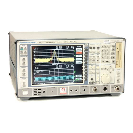
Rohde & Schwarz FSEA20 Operating Manual (438 pages)
SPECTRUM ANALYZER
Brand:
Rohde & Schwarz
| Category:
Measuring Instruments
| Size: 1.75 MB
Table of Contents
Contents - Chapter 5 "Remote Control - "Basics"
18
Volume
2
Safety Instructions
7
Basic Safety Instructions
7
Service Manual
16
Table of Contents
18
Remote Control - Basics
20
Introduction
20
Brief Instructions
21
Switchover to Remote Control
21
Indications During Remote Control
21
Remote Control Via IEC Bus
22
Setting the Device Address
22
Return to Manual Operation
22
Remote Control Via RS-232-Interface
23
Setting the Transmission Parameters
23
Return to Manual Operation
23
Limitations
24
Remote Control Via RSIB Interface
25
Windows Environment
25
Unix Enviroment - with Windows NT Controller
25
Remote Control
25
Return to Manual Operation
25
Messages
26
IEE/IEEE-Bus Interface Messages
26
RSIB Interface Messages
26
Device Messages (Commands and Device Responses)
27
Structure and Syntax of the Device Messages
28
SCPI Introduction
28
Structure of a Command
28
Structure of a Command Line
31
Responses to Queries
31
Parameters
32
Overview of Syntax Elements
33
Instrument Model and Command Processing
34
Input Unit
34
Command Recognition
35
Data Set and Instrument Hardware
35
Status Reporting System
35
Output Unit
36
Command Sequence and Command Synchronization
36
Status Reporting System
37
Structure of an SCPI Status Register
37
Overview of the Status Registers
39
Description of the Status Registers
40
Status Byte (STB) and Service Request Enable Register (SRE)
40
IST Flag and Parallel Poll Enable Register (PPE)
41
Event-Status Register (ESR) and Event-Status-Enable Register (ESE)
41
Status:operation Register
42
Status:questionable Register
43
Status Questionable:acplimit Register
44
Status Questionable:frequency Register
45
Status Questionable:limit Register
46
Status Questionable:lmargin Register
47
Status Questionable:power Register
48
Status Questionable:sync Register
49
Status Questionable:transducer Register
50
Application of the Status Reporting Systems
51
Service Request, Making Use of the Hierarchy Structure
51
Serial Poll
51
Parallel Poll
52
Query by Means of Commands
52
Error-Queue Query
52
Resetting Values of the Status Reporting System
53
Contents - Description of Commands
55
1 Chapter 1 I-5.1
123
Format Subsystem
174
Sense Subsystem
220
Sense:ademod Subsystem
220
Sense:average Subsystem
222
Sense:bandwidth Subsystem
224
Sense:correction-Subsystem
228
Sense:detector Subsystem
238
Sense:ddemod Subsystem
239
Sense:filter Subsystem
247
Sense:frequency Subsystem
250
Sense:mixer - Subsystem
254
Sense:msummary Subsystem
258
Sense:power Subsystem
260
Sense:roscillator Subsystem
263
Sense:sweep Subsystem
264
Sense:tv Subsystem
268
Source Subsystem
269
Status Subsystem
271
System Subsystem
283
Trace Subsystem
290
Trigger Subsystem
292
UNIT Subsystem
297
Alphabetical List of Commands
298
Table of Softkeys with IEC/IEEE-Bus Command Assignment
316
Basic Instrument - Signal Analysis Mode
316
FREQUENCY Key Group
316
LEVEL Key Group
318
INPUT Key
319
MARKER Key Group
320
LINES Key Group
324
TRACE Key Group
326
SWEEP Key Group
328
CONFIGURATION Key Group
334
STATUS Key Group
336
HARDCOPY Key Group
337
MEMORY Key Group
338
USER Key
340
Operating Mode Vector-Signal Analyzer (Option FSE-B7)
341
CONFIGURATION Key Group - Digital Demodulation
341
CONFIGURATION Key Group - Analog Demodulation
345
LEVEL Key Group
347
INPUT Key
348
MARKER Key Group
348
LINES Key Group
350
TRACE Key Group
351
SWEEP Key Group
352
TRIGGER Key Group - Digital Demodulation
352
TRIGGER Key Group - Analog Demodulation
353
Operating Mode Tracking Generator (Option FSE-B8 to B11)
354
CONFIGURATION Key Group
354
Operating Mode TV Demodulation (Option FSE-B3)
355
CONFIGURATION Key Group
355
SWEEP Key Group
355
Operating Mode GSM BTS Analyzer (Option FSE-K11)
356
CONFIGURATION Key Group
356
Operating Mode GSM MS Analyzer (Option FSE-K10)
366
CONFIGURATION Key Group
366
2 Chapter 2 External Mixer Output (Option FSE-B21)
376
INPUT Key Group
376
Contents - Chapter 7 "Remote Control - Programming
378
Programming Examples
380
Programming Via IEC/IEEE Bus
380
Including IEC-Bus Library for Quickbasic
380
Initialization and Default Status
380
Initiate Controller
380
Initiate Instrument
380
Transmission of Instrument Setting Commands
381
Switchover to Manual Control
381
Reading out Instrument Settings
381
Positioning a Marker and Displaying Values
381
Command Synchronization
382
Service Request
383
Programming Via the RSIB Interface
385
Visual Basic
385
Visual Basic for Applications (Winword and Excel)
388
C / C
389
Interfaces"
392
Maintenance
394
Mechanical Maintenance
394
Electrical Maintenance
394
Testing the Level Measuring Accuracy
394
Testing the Frequency Accuracy
394
Maintenance and Instrument Interfaces
394
Instrument Interfaces
395
IEC Bus Interface
395
Interface Characteristics
395
Bus Lines
396
Interface Functions
397
IEC Bus Messages
397
Interface Messages
397
Instrument Messages
398
RS-232-C Interface
399
Interface Characteristics
399
Signal Lines
399
Interface Functions
400
Transmission Parameters
400
Handshake
401
RSIB Interface
403
Windows Environment
403
Unix Environment
404
RSIB Interface Functions
405
Variables Ibsta, Iberr, Ibcntl
405
List of Interface Functions
406
Description of Interface Functions
407
User Interface (USER)
414
Printer Interface (LPT)
415
Measurement Converters (PROBE CODE)
416
Probe Connector (PROBE POWER)
416
AF-Output (AF OUTPUT)
417
IF Output 21.4 Mhz (21.4 Mhz OUT)
417
Video Output (VIDEO OUT)
417
Reference Output/Input (EXT REF IN/OUT)
417
Sweep Output (SWEEP)
417
External Trigger Input (EXT TRIGGER/GATE)
417
Noise Source Control (NOISE SOURCE)
417
External Keyboard (KEYBOARD)
418
Mouse Connector (MOUSE)
418
Monitor Connector (MONITOR)
418
List of Error Messages
422
SCPI-Specific Error Messages
422
Command Error - Faulty Command; Sets Bit 5 in the ESR Register
422
Execution Error - Error on Execution of a Command; Sets Bit 4 in the ESR Register
425
Device Specific Error; Sets Bit 3 in the ESR Register
428
Query Error - Error in Data Request; Sets Bit 2 in the ESR Register
428
Advertisement
Advertisement
Related Products
Rohde & Schwarz FSE-B7
Rohde & Schwarz FSEA30
Rohde & Schwarz FSEB20
Rohde & Schwarz FSEB30
Rohde & Schwarz FSEM20
Rohde & Schwarz FSEM30
Rohde & Schwarz FSEK20
Rohde & Schwarz FSEK30
Rohde & Schwarz FSMR series
Rohde & Schwarz FSVA3000
Rohde & Schwarz Categories
Measuring Instruments
Test Equipment
Power Supply
Portable Generator
Accessories
More Rohde & Schwarz Manuals
Login
Sign In
OR
Sign in with Facebook
Sign in with Google
Upload manual
Upload from disk
Upload from URL