Sign In
Upload
Manuals
Brands
Rockwell Automation Manuals
DC Drives
Reliance Electric MD65
Rockwell Automation Reliance Electric MD65 Manuals
Manuals and User Guides for Rockwell Automation Reliance Electric MD65. We have
2
Rockwell Automation Reliance Electric MD65 manuals available for free PDF download: User Manual
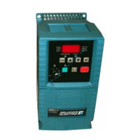
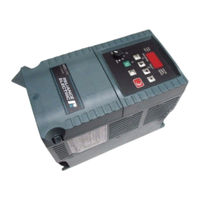
Rockwell Automation Reliance Electric MD65 User Manual (188 pages)
AC Drive
Brand:
Rockwell Automation
| Category:
DC Drives
| Size: 4.18 MB
Table of Contents
Table of Contents
4
Chapter 1 Introduction
12
Getting Assistance from Reliance Electric
12
Chapter 2 About the MD65 Drive
14
Identifying the Drive by Model Number
14
Figure 2.1 - Identifying the Drive by Model Number
14
MD65 Drive Ratings, Model Numbers, and Frame Sizes
15
Table 2.1 - Drive Ratings, Model Numbers, and Frame Sizes
15
Kits and Accessories
16
Table 2.2 - Standard Kits and Accessories
16
Storage Guidelines
17
Chapter 3 Mounting the Drive
18
General Requirements for the Installation Site
18
Operating Conditions
19
Minimum Mounting Clearances
19
Figure 3.1 - Minimum Mounting Clearances
19
Table 3.1 - Ambient Operating Temperatures and Mounting Clearances
19
Mounting Dimensions for the MD65 Drive
20
Figure 3.2 - Drive Dimensions and Weights
20
Figure 3.3 - Drive Dimensions - NEMA 1/IP30 Kit Without
21
Figure 3.4 - Drive Dimensions - NEMA 1/IP30 Kit with
22
Mounting the Drive
23
Protecting the Drive from Debris
23
Table 3.2 - Mounting Specifications
23
Chapter 4 Grounding the Drive
24
Figure 4.1 - Typical Grounding
24
RFI Filter Grounding
25
Chapter 5 Installing Power Wiring
26
Opening the Cover
26
Figure 5.1 - Opening the Cover
26
Verifying Drive AC Input Ratings Match Available Power
27
Ungrounded Distribution Systems
27
Figure 5.2 - Removing the Finger Guard
27
Figure 5.3 - Removing the Jumper
28
Figure 5.4 - Phase-To-Ground MOV Removal
28
Input Power Conditioning
29
Power Wiring Specifications
29
Table 5.1 - Corrective Actions for Input Power Conditions
29
Table 5.2 - Power Wiring Specifications
29
Power Terminal Block Connections
30
Figure 5.5 - Power Terminal Block Connections
30
Table 5.3 - Power Terminal Block Specifications
30
Fuses and Circuit Breakers
31
Installations
31
Table 5.4 - Drive, Fuse, and Circuit Breaker Ratings
32
Table 5.5 - Shielded Motor Cable Types Acceptable for 200-600 Volt Installations
34
Reflected Wave Protection
35
Output Disconnect
35
Table 5.6 - Maximum Cable Length Recommendation
35
Chapter 6 Installing Control Wiring
36
Stop Circuit Requirements
36
Motor Start/Stop Precautions
37
I/O Wiring Recommendations
38
Maximum Control Wire Length Recommendations
38
Table 6.1 - Recommended Control and Signal Wire
38
Table 6.2 - I/O Terminal Block Specifications
38
Wiring the Control Terminal Block
39
Figure 6.1 - Control Terminal Block
39
Table 6.3 - Control Terminal Definitions and Related Parameters
40
I/O Wiring Examples
41
Table 6.4 - Typical Multiple Drive Connection Examples
44
Typical Multiple Drive Connection Examples
44
Start and Speed Reference Control
45
Figure 6.2 - Override Priority for the Speed Reference Command
45
Accel/Decel Selection
46
Figure 6.3 - Accel/Decel Selection
46
Chapter 7 Completing the Installation
48
Checking the Installation before Applying Power to the Drive
48
Powering up after Installation Is Complete
49
Chapter 8 Using the Integral Keypad to Program and Control the Drive
50
Keypad Components
50
Figure 8.1 - Integral Keypad
50
Display Description
51
LED Descriptions
51
Table 8.1 - LED Descriptions
51
Key Descriptions
52
Table 8.2 - Key Descriptions
52
About Parameters
53
How Parameters Are Organized
53
Viewing and Adjusting Basic (P) and Advanced (A) Parameters
54
Table 8.3 - Viewing and Adjusting Basic (P) and Advanced (A)
54
Viewing the Display (D) Parameters
55
Table 8.4 - Viewing the Display (D) Parameters
55
Chapter 9 Parameter Descriptions
56
Basic Program Group Parameters
57
Figure 9.1 - Accel Time 1 (P039)
61
Figure 9.2 - Decel Time 1 (P040)
62
Advanced Group Parameters
63
Table 9.1 - Trip Points for Digital Output Relay
68
Table 9.2 - On/Off Points for the Opto Outputs
71
Table 9.3 - A064 Options
72
Table 9.4 - Analog Output Signal Mode Selections
72
Figure 9.3 - Accel Time 2 (A067)
73
Figure 9.4 - Decel Time 2 (A068)
74
Table 9.5 - Selecting the Reference Source Using Presets
75
Figure 9.5 - DC Brake Level (A081)
76
Figure 9.6 - S Curve % (A083) Example
77
Figure 9.7 - Boost Select (A084)
78
Figure 9.8 - Start Boost (A085)
79
Figure 9.9 - Motor OL Select (A090)
80
Figure 9.10 - Derating Guidelines Based on PWM Frequency (A091) Selection
81
Figure 9.11 - Anlg in 0-10V lo (A110)
87
Figure 9.12 - Skip Freq Band (A120)
90
Table 9.6 - Related Parameters for Stp Logic Parameters (A140-A147)
96
Figure 9.13 - Digit Settings
98
Figure 9.14 - EM BRK off Delay
99
Display Group Parameters
101
Figure 9.15 - Drive Status (D006) Bit Definitions
102
Figure 9.16 - Control Source (D012) Bit Definitions
103
Figure 9.17 - Contrl in Status (D013) Bit Definitions
104
Figure 9.18 - Dig in Status (D014) Bit Definitions
104
Figure 9.19 - Comm Status (D015) Bit Definitions
105
Chapter 10 Troubleshooting the Drive
108
Fault Codes
108
Manually Clearing Faults
109
Automatically Clearing Faults (Auto Restart Feature)
109
Table 10.1 - Fault Descriptions and Corrective Actions
110
Troubleshooting Tables
114
Problem: Drive Does Not Start from Terminal Block Start or Run Inputs
114
Table 10.2 - Problem: Drive Does Not Start from Terminal Block
114
Problem: Drive Does Not Start from Integral Keypad
115
Problem: Drive Does Not Respond to Changes in Speed Command
115
Table 10.3 - Problem: Drive Does Not Start from Integral Keypad
115
Table 10.4 - Problem: Drive Does Not Respond to Changes in
115
Problem: Motor Does Not Start
116
Problem: Motor And/Or Drive will Not Accelerate to Commanded Speed
117
Problem: Motor Operation Is Unstable
117
Table 10.5 - Problem: Motor And/Or Drive will Not Accelerate to
117
Table 10.6 - Problem: Motor Operation Is Unstable
117
Problem: Drive will Not Reverse Motor
118
Direction
118
Problem: Drive Does Not Power up
118
Table 10.7 - Problem: Drive will Not Reverse Motor Direction
118
Appendix A Technical Specifications
120
Advertisement
Rockwell Automation Reliance Electric MD65 User Manual (186 pages)
Brand:
Rockwell Automation
| Category:
Servo Drives
| Size: 88.18 MB
Table of Contents
Table of Contents
3
Getting Assistance from Reliance Electric
11
About the MD65 Drive
13
Identifying the Drive by Model Numbet
13
MD65 Drive Ratings, Model Numbers, and
14
Kits and ACCESSOTSICS
15
Mounting the Drive
17
General Requirementsfor the Installation Site
17
Operating Conditions
18
Minimum Mounting Clearances
18
Mounting Dimensions for the MD65 Drive
19
Mounting the Drive
22
Protecting the Drive from Debris
22
Grounding the Drive
23
Installing Power Wiring
25
Opening the Cover
25
Verifying Drive AC Input Ratings Match
26
Ungroundeddistribution Systems
26
Input Power Conditioning
28
Power Terminal Block Connections
29
Fuses and Circuit Breakers 0.0
30
Reflected Wave Protection
34
Installing Control Wiring
35
Stop Circuit Requirement
35
Motor Start/Stop Precautions
36
I/O Wiring Recommendations
37
Maximum Control Wire Length
37
Wiring the Control Terminal BIOCK
38
I/O Wiring Examples
40
Typical Multiple Drive Connection Examples
43
Start and Speed Reference Control
44
Accel/Decel Selection
45
Completing the Installation
47
Checking Theinstallation before Applying Power to the Drive
47
Powering up Afterinstallation Is Complete
48
Using the Integral Keypad to Program and Control the Drive
49
Keypad Component
49
Display Description
50
LED Descriptions
50
Key Descriptionns
51
About Parameters
52
How Parameters Are Organized
52
Viewing and Adjusting Basic (P) and Advanced(A)
53
Viewing the Display (D) Parameters
54
Parameter Descriptions
55
Basic Program Group Parameters
56
Advanced Group Parameters
62
Display Group Parameters
100
Troubleshooting the Drive
107
Fault Cod@S
107
Manually Clearing Faults "0.0.0.0
108
Automatically Clearing Faults (Auto Restart Feature) "2.0
108
Troubleshooting Tables
113
Problem: Drive Does Not Start from Terminal Block Start or Run Inputs
113
Problem: Drive Does Not Start from Integral Keypad
114
Problem: Drive Does Not Respond to Changesin Speed Command
114
4Problem: Motor Does Notstart
115
Problem: Motor And/Or Drive will Not Accelerate to Commanded Speed
116
Problem: Motor Operation Is Unstable
116
Problem: Drive will Not Reverse Motor Dif@Ction 20.22
117
Problem: Drive Does Not Power up
117
Technical Specifications
119
Advertisement
Related Products
Rockwell Automation MD60
Rockwell Automation Reliance electricWebPak 3000
Rockwell Automation Reliance electric SP600 Series
Rockwell Automation Reliance electric 6SP201-2P2
Rockwell Automation Reliance electric 6SP201-4P2
Rockwell Automation Reliance electric 6SP201-6P8
Rockwell Automation Reliance electric 6SP201-9P6
Rockwell Automation Reliance electric 6SP201-015
Rockwell Automation Reliance electric 6SP201-022
Rockwell Automation Reliance electric 6SP201-028
Rockwell Automation Categories
Controller
Control Unit
Power Supply
DC Drives
Industrial Equipment
More Rockwell Automation Manuals
Login
Sign In
OR
Sign in with Facebook
Sign in with Google
Upload manual
Upload from disk
Upload from URL