Sign In
Upload
Manuals
Brands
Rockwell Automation Manuals
Controller
Allen-Bradley PowerFlex 7000
Rockwell Automation Allen-Bradley PowerFlex 7000 Manuals
Manuals and User Guides for Rockwell Automation Allen-Bradley PowerFlex 7000. We have
5
Rockwell Automation Allen-Bradley PowerFlex 7000 manuals available for free PDF download: User Manual, Installation Instructions Manual
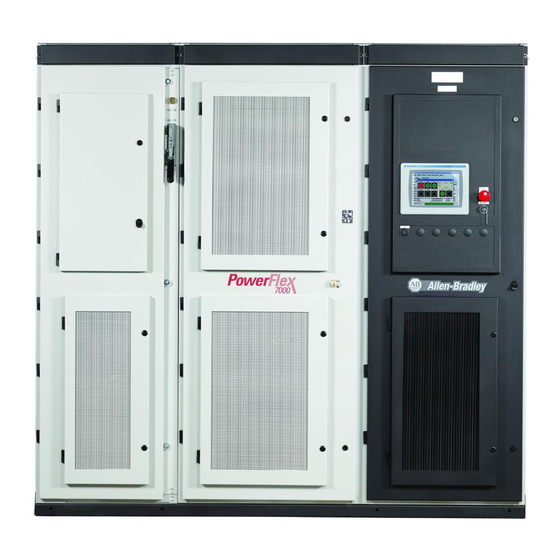
Rockwell Automation Allen-Bradley PowerFlex 7000 User Manual (434 pages)
Medium Voltage AC Drive Liquid-Cooled, C Frame ForGe Control
Brand:
Rockwell Automation
| Category:
DC Drives
| Size: 44.56 MB
Table of Contents
Table of Contents
3
Preface
13
Summary of Changes
13
What Is Not in this Manual
13
Who Should Use this Manual
13
Additional Resources
14
Commissioning Support
14
General Precautions
14
Chapter 1 Introduction
15
Liquid Cooling
15
Benefits of Liquid Cooling Include
15
Benefits of the 7000L "C" Frame Liquid-Cooled Drive
16
Overview of Drive
15
Topology
17
Rectifier Designs
18
18 Pulse Rectifier
18
Active Front End (AFE Rectifier)
18
Direct-To-Drive" Technology
19
Motor Compatibility
21
SGCT Features and Benefits
22
Specifications
23
Simplified Electrical Drawings
27
Control Overview
29
Control Hardware
30
Direct Vector Control
30
Operator Interface
31
Chapter 2 Safety and Codes
33
Drive Installation
33
Transportation and Handling
33
Overhead Lifting
34
Rod or Pipe Rollers
35
Fork Lift Trucks
36
Storage
36
Unpacking and Inspection
33
Siting of the Drive
36
Site Considerations
36
Installation
37
Joining Shipping Splits
38
Connect the Sections
39
Tools Required (Not Supplied)
39
Install CPVC Piping Splices
39
Connect Power: M+, L+, M-, L- Power Bus
42
Control Wiring Connections
47
Removal of DC Link Choke Turnbuckle Supports
54
Removal of Lifting Angles
54
Shock Indication Labels
55
Installation of Exhaust Air Hood
56
Internally Mounted Fans
57
Externally Mounted Fans and Fan Hood
58
Typical Powerflex 7000L Drive Structure Layout
59
Control/Cabling Cabinet
59
Major Components
59
IEC Component and Device Designation
68
Power Wiring Selection
68
General Notes
68
Cable Insulation
69
Power Cabling Access
71
Access the Customer Power Cable Terminations
71
Power Connections
74
Incoming Connections
74
Liquid Connections
75
Liquid-To-Air Heat Exchangers
75
Pipe Materials and Layout
76
External Piping to the Drive
77
External Piping Cleaning
77
Controlled Siphon into Open-Top Reservoir
78
Liquid-To-Liquid Heat Exchangers
80
Power and Control Wiring
83
Control Cables
83
Encoder Installation Guidelines
83
Information Regarding Termination of Customer Cables
86
Grounding Practices
87
Grounding Guidelines and Practices for Drive Signal and Safety Grounds
88
Grounding Requirements and Grounding Specification for Customers and Power Integrators
88
Identification of Types of Electrical Supplies - Grounded and Ungrounded Systems
89
Ground Bus
89
Interlocking
89
Chapter 3 Chapter Objectives
91
Operator Interface
91
Terminology
91
Overview
92
Keypad
93
Function (Softkeys) Keys
93
Cursor (Selection) Keys
93
Data Entry Keys
94
What Is a Screen
94
Components
94
Information Windows
96
Accessing/Writing to Drive
96
Communication Error
96
Languange Changing
97
General Operation
98
Operator Interface Power-Up Sequence
99
Top Level Menu
99
How to
100
Obtain Help
100
Related Topics
101
Help on Help
102
Modify Operator Interface Operation (Utility)
102
Changing Backlight Delay
103
Changing Contrast
104
Setting Time
104
Setting Date
105
Selecting Meters
106
Viewing Revision Levels
108
Transfer Data in Memory
109
Picking an Access Level
110
Select a Parameter
110
Via Groups
110
Via Name
111
Via Code
113
Edit Text
114
Configure the Drive
116
Enter/Modify an Access Level
116
Drive Setup
120
Language Selection
121
Modify Parameters
122
Numerical Value
122
Enumerated Value
124
Bit Encoded Value
125
Analog Ports
126
Fault Masks
128
User Definable External Text
131
Plc
132
Xio
133
Message Prompting
134
Store/Retrieve Configuration (NVRAM)
135
Initialize
135
Save
135
Load
136
Display Parameters
137
Custom Group
138
View Drive Status
139
View and Reset Alarms
140
Help for Alarms
141
Perform Diagnostic Trending
142
Assigning a Trace
144
Setting the Trigger
144
Defining Sample Rate and Positioning
146
Starting the Trace
146
Request Printouts
142
Flash Memory Transfers
148
Format Flash Card
149
View a Directory
150
Select a Filename
151
Enter a Filename
151
Loading Programs (Firmware)
152
Parameter Transfers
153
Upload to Operator Interface
154
Download from Operator Interface
154
Upload to Memory Card
155
Download from Memory Card
155
Parameter File Format
156
Loading Language Modules
156
Advanced Screen Operations
158
Communications Statistics
158
Protocol Analyzer
159
Print Screen
160
Memory Dump
160
Database Download
162
System Programming
158
Operator Interface Menu Hierarchy Chart
162
What Does It Show
162
How Do You Read It
163
Example
163
PCMCIA Memory Card Installation Data
167
Description
167
Installing the Memory Card
167
Chapter 4 Start-Up Commissioning Services
169
Drive Commissioning
169
Commissioning the Drive
170
Commissioning
169
Powerflex 7000 'C' Frame Pre-Commissioning Checklist
171
Receiving and Unpacking
171
Installation / Mounting
172
Safety
172
Control Wiring
172
Power Wiring
173
Drive Line-Up Status
173
Cooling System Status
173
Pre-Commissioning Responsibilities
171
Commissioning Preparation
175
Recommended Tools and Equipment
175
Additional Manuals
176
Powerflex 7000 "C" Frame Manual
176
Powerflex 7000 Parameters
176
Resources Required to Complete Drive Commissioning
176
Technical Publications
176
Important Note for Commissioning Engineer
177
Key Steps to Commissioning a Powerflex 7000 Drive
178
Powerflex 7000 "C" Frame Commissioning Datasheets
179
Powerflex 7000 "C" Frame Drive Commissioning Checklist
180
Drive Application Review
183
Rockwell Automation Drive Line-Up Drawings
183
Electrical System One-Line Diagram
184
Verify One-Line Diagram on Site
184
Inspect Process
184
Safety Tests
185
Lockout Tagout
185
Step down Transformer Fusing
186
Fuse and O/L Protection
186
Installation Review
186
Inspect for Shipping Damage
186
Inspect Cabinets for Debris
187
Protective Barriers
187
Component Grounding
187
Information on Splice Kits
188
Power Cabling
188
Control Wiring
188
Liquid-Cooling Connections
189
Service Data
190
Why this Information Is Needed
190
Customer Information
191
Control Power off Tests
195
Interlocking
195
Resistance Checks
196
SGCT Testing
197
SGCT Anode-To-Cathode Resistance
198
Snubber Resistance (SGCT Device)
199
Snubber Capacitance (SGCT Device)
200
SCR Testing
200
SCR Anode-To-Cathode Resistance
201
SCR Sharing Resistance Test
202
SCR Gate-To-Cathode Resistance
203
Snubber Resistance (SCR Device)
204
Snubber Capacitance (SCR Device)
205
Control Power Tests
206
Three-Phase Input
207
Three-Phase Input / Single Phase Input
207
Power Supply Tests
208
Circuit Board Healthy Lights
208
Control Power Transformer (CPT)
208
AC/DC Converter (PS1)
209
DC/DC Converter (PS2)
210
SGCT Power Supplies (IGDPS)
211
IGDPS Board Leds
214
Commissioning the Cooling System
214
Heat Exchanger Checks
215
Pumping Cabinet Control Power Checks
216
System Fill
217
System Fill and Air Venting
218
Normal Operation
220
Gating Tests
220
Gating Test Mode
220
SCR Firing Test
222
SGCT Firing Test
224
System Test
225
System Test Mode
225
Start/Stop Control Circuit
226
Status Indicators
227
Analog I/O
227
Configurable Alarms
231
18 Pulse Phasing Test
231
Line Terminal Resistance Measurements
232
Application of Medium Voltage
233
Input Phasing Check
233
DC Current Test
235
Tuning Procedure
238
Rectifier
238
Motor Impedance
243
Fluxspeed Regulator [INDUCTION MOTORS]
244
Fluxspeed Regulator [SYNCHRONOUS MOTORS]
249
Running the Load
253
Motor Starting Torque
253
Reaching Specific Load Points
253
Capturing Data
255
Drive Input Voltage Phasing Checks
255
Summary
255
(Required for AFE Drives Only)
257
Summary
257
Harmonic Analysis
257
DC Current Test
258
Summary
258
Load Test
259
Synchronous Transfer
261
Chapter 5
265
Component Definition and Maintenance
265
Control / Cabling Cabinet Components
265
Voltage-Sensing Assembly
268
Voltage-Sensing Circuit Board Assembly Replacement
268
Input Transient Protection
269
Overview
269
Transient Suppression Network (TSN)
270
Description
270
MOV Suppressor
270
MOV Fuse
271
Transient Suppression Network Fuse Replacement
272
Metal-Oxide Varistor Replacement
273
Surge Arresters
274
Description
274
Operation
275
Surge Arrester Replacement
276
Field Test and Care
277
Output Grounding Network Capacitor Replacement
277
Ground Filter Replacement
279
Hall Effect Sensor Replacement
280
Current Transformer Replacement
281
Filter Capacitor Cabinet
282
Filter Capacitors
282
Filter Capacitor Replacement
284
Testing Filter Capacitors
285
Converter Cabinet Components
287
Converter Cabinet
289
Powercage
289
SGCT and Snubber Circuit
291
Checking Clamping Pressure
292
Clamping Pressure Adjustment
292
Symmetrical Gate Commutated Thyristor Replacement
293
Board Replacement
296
Detachment of Coolant System from Powercage Modules
299
Reconnecting the Coolant System to a Powercage Module
303
Silicon Controlled Rectifier and SCR Self-Powered Gate Driver
299
Chill Block Removal and Replacement
303
Instructions for Removing Chill Block Assembly
303
Instructions for Inserting Chill Block Assembly
304
Powercage Removal and Replacement
305
Snubber Resistors
306
Testing Snubber Resistors
307
Sharing Resistors
307
Testing Sharing Resistors
308
Snubber and Sharing Resistor Replacement
309
Snubber Capacitor Replacement
311
Self-Powered Gate Driver Board - SPGDB
312
Description
312
Board Calibration
312
Test Points Description
312
Terminal/Connections Description
313
Testing Procedure for SCR Self-Powered Gate Driver Board
314
Equipment Needed
314
Procedure
314
Fiber Optic Cabling
318
DC Link Reactor
320
Control Power Components
322
Ride-Through
322
AC/DC Power Supply
323
Description
323
Location
324
Terminal / Connections Descriptions
325
Replacement Procedure
326
UPS Option
327
UPS Replacement Procedure
328
Cooling System
329
Cooling Circuit
330
Chill Blocks
330
Coolant Pumps
330
Pump Maintenance and Replacement
331
Pump Seal Replacement
331
Pump Replacement with Drive Running
332
Piping, Tubing and Connectors
334
Non-Return Valves
334
Pressure Indicator
335
Pressure Switch
335
Thermostatic Valve
335
Thermostatic Valve Replacement
335
Repair Instructions - Element Testing
336
Element Replacing
336
Heat Exchanger
337
Fluid Conductivity
338
Temperature Sensor
338
De-Ionizing Cartridge and Mesh Filter
339
Replacing the Mesh Filters
340
Reservoir Circuit
341
Fluid Top-Up
341
Strainers
341
Coolant
342
Maintaining Coolant Ratio
343
Leakage Checks
344
System Drain
345
Low Voltage Control Section
345
DC/DC Power Supplydescription
346
Description
346
Terminal/Connections Descriptions
347
Replacement Procedure for DC/DC Power Supply
348
Printed Circuit Board Replacement
349
IO Connectors on Control Boards
349
Drive Processor Module
350
Drive Processor Module Replacement
352
Instructions to Replace the Drive Processor Module
352
ACB Analog Control Board
354
Leds
358
Interface Module (IFM)
358
Analog Inputs and Outputs
358
Current Loop Transmitter
359
Isolated Process Receiver
359
Non-Isolated Process Outputs
360
Auxiliary +24V Power Supply
361
ACB Analog Control Board Replacement
361
Tachometer Feedback Board
362
Encoder Options
362
Quadrature Encoder Operation
365
Positional Encoder Operations
366
Positional Encoder Guidelines
367
External Input/Output Boards
368
External Input/Output Board Replacement
369
Optical Interface Boards (OIB)
370
Optical Interface Board Replacement
371
Optical Interface Base Board (OIBB)
373
Optical Interface Base Board Test Points
374
Downloading Firmware
375
Introduction
375
Overview
375
Powerflex 7000 in Download Mode
378
Reloading the Parameters
381
Setting Elapsed Time
382
Downloading the Terminal Firmware
383
Using Flash Memory Card
383
Dosfwdl
383
Method
384
Setting up Diagnostic Trending
384
Diagnostic Setup
385
Setting up the Trend
385
Printing (Uploading) Data from the Drive
391
Overview
391
Creating an Empty Notepad (.Txt) File
392
Setting up Hyperterminal Connection
394
Uploading the Data from the Drive
396
Printing (Uploading) Control Data
399
Set up Hyperterminal Connection
400
Printing Control Data
401
Environmental Considerations
403
Hazardous Materials
403
Disposal
405
Operational Maintenance
405
Preventive Maintenance Check List
405
Annual Maintenance
406
Initial Information Gathering
406
Physical Checks
407
Power)
407
Control Power Checks (no Medium Voltage)
408
Final Power Checks before Restarting
408
Additional Tasks During Preventive Maintenance
409
Final Reporting
409
Time Estimations
410
Tool / Parts / Information Requirements
410
Appendix A Rating Code
415
Powerflex 7000 Drive Selection Explanation
415
When Is an Encoder Required
416
Powerflex 7000 Drive Performance (Torque Capabilities)
417
Glossary of Terms
418
Torque Requirements
421
Appendix B Drive Meggering
423
Meggering the Powerflex 7000
423
Equipment Required
424
Procedure
424
Appendix D
429
Powerflex 7000 Maintenance Schedule
429
Advertisement
Rockwell Automation Allen-Bradley PowerFlex 7000 User Manual (228 pages)
Medium Voltage AC Drive Liquid-Cooled ('C' Frame)-ForGe Control
Brand:
Rockwell Automation
| Category:
Industrial Equipment
| Size: 27.87 MB
Table of Contents
Table of Contents
3
Preface
9
Summary of Changes
9
About this Publication
9
Download Firmware, AOP, EDS, and Other Files
9
Who Should Use this Manual
9
What Is Not in this Manual
10
Commissioning Support
10
General Precautions
11
Abbreviations
12
Additional Resources
13
Overview of Drive
15
Introduction
15
Liquid Cooling
15
Benefits of Liquid Cooling
15
Topology
17
Rectifier Designs
17
18-Pulse Rectifier
17
Active Front End (AFE Rectifier)
18
Direct-To-Drive Technology
19
Motor Compatibility
20
Symmetrical Gate-Commutated Thyristor (SGCT) Features and Benefits
20
Simplified Electrical Drawings
22
Control Overview
23
Direct Vector Control
24
Control Hardware
24
Functional Safety
25
Safe Torque off
25
Operator Interface
26
Basic Configurations
26
Drive Installation
29
Safety and Codes
29
Unpacking and Inspection
29
Transportation and Handling
30
Overhead Lifting
30
Rod or Pipe Rollers
31
Fork Lift Trucks
32
Storage
32
Siting of the Drive
32
Site Considerations
32
Installation
33
Joining Shipping Splits
33
Connect the Sections
34
Tools Required (Not Supplied)
34
Install CPVC Piping Splices
34
Connect Power: M+, L+, M-, L- Power Bus
37
Control Wiring Connections
42
Removal of DC Link Choke Turnbuckle Supports
49
Removal of Lifting Angles
50
Shock Indication Labels
50
Installation of Exhaust Air Hood
51
Internally-Mounted Fans
52
Externally-Mounted Fans and Fan Hood
52
Typical Powerflex 7000L Drive Structure Layout
54
Control/Cabling Cabinet
54
Major Components
55
IEC Component and Device Designation
60
Power Cabling Access
60
Access the Customer Power Cable Terminations
60
Power Connections
63
Incoming Connections
63
Liquid Connections
64
Liquid-To-Air Heat Exchangers
64
Pipe Materials and Layout
65
External Piping to the Drive
66
External Piping Cleaning
66
Controlled Siphon into Open-Top Reservoir
67
Liquid-To-Liquid Heat Exchangers
68
Power and Control Wiring
71
Control Cables
71
Encoder Installation Guidelines
71
Information Regarding Termination of Customer Cables
73
Grounding Practices
74
Grounding Guidelines and Practices for Drive Signal and Safety
75
Grounds
75
Grounding Requirements and Grounding Specification for Customers and Power Integrators
76
Identification of Types of Electrical Supplies - Grounded and Ungrounded Systems
76
Ground Bus
76
Interlocking
76
Power Component Definition and Maintenance
77
Control / Cabling Cabinet Components
77
Voltage Sensing Assembly
80
Voltage Sensing Circuit Board Assembly Replacement
80
Input Transient Protection
81
Overview
81
Transient Suppression Network (TSN)
81
Description
81
MOV Suppressor
82
MOV Fuse
83
Transient Suppression Network Fuse Replacement
84
Metal Oxide Varistor Replacement
85
Surge Arresters
85
Description
85
Operation
86
Surge Arrester Replacement
87
Field Test and Care
88
Output Grounding Network Capacitor Replacement
88
Ground Filter Replacement
90
Hall Effect Sensor Replacement
90
Current Transformer Replacement
91
Filter Capacitor Cabinet
92
Filter Capacitors
92
Filter Capacitor Replacement
93
Testing Filter Capacitors
94
Converter Cabinet
95
Converter Cabinet Components
96
Powercage
98
SGCT and Snubber Circuit
100
Checking Clamping Pressure
101
Clamping Pressure Adjustment
101
Symmetrical Gate Commutated Thyristor Replacement
103
Silicon Controlled Rectifier and SCR Self-Powered Gate Driver
105
Board Replacement
105
Detachment of Coolant System from Powercage Modules
107
Reconnecting the Coolant System to a Powercage Module
110
Chill Block Replacement
110
Remove the Chill Block Assembly
110
Insert the Chill Block Assembly
111
Powercage Replacement
112
Snubber Resistors
113
Testing Snubber Resistors
113
Sharing Resistors
114
Testing Sharing Resistors
114
Snubber and Sharing Resistor Replacement
115
Snubber Capacitor Replacement
116
Self-Powered Gate Driver Board - SPGDB
117
Description
117
Board Calibration
118
Test Points Description
118
Terminal/Connections Description
119
Testing Procedure for SCR Self-Powered Gate Driver Board
120
Required Equipment
120
Procedure
120
Fiber Optic Cabling
123
DC Link Reactor
125
Cooling System
127
Cooling Circuit
128
Chill Blocks
128
Coolant Pumps
128
Pump Maintenance and Replacement
129
Pump Maintenance Guidelines
129
Pump Replacement with Drive Running
130
Piping, Tubing, and Connectors
131
Non-Return Valves
131
Pressure Indicator
132
Pressure Switch
132
Thermostatic Valve
132
Thermostatic Valve Replacement
133
Repair Instructions - Element Testing
133
Element Replacing
134
Heat Exchanger
134
Pumping Cabinet Control Power Checks
136
Fluid Conductivity
136
Temperature Sensor
137
De-Ionizing Cartridge and Mesh Filter
137
Addressing High Coolant Conductivity
139
Reservoir Circuit
140
Fluid Top-Up
140
Strainers
140
Coolant
141
Maintaining Coolant Ratio
141
Leakage Checks
142
System Drain
143
System Fill
143
System Fill and Air Venting
145
Normal Operation
146
Control Component Definition and Maintenance
147
Control Power Components
147
Ride-Through
147
AC/DC Power Supply
149
Description
149
Terminal / Connections Descriptions
150
Replacement Procedure
151
UPS Option
152
Replace the UPS
153
Low Voltage Control Section
154
DC/DC Power Supply Description
155
Terminal/Connections Descriptions
155
Replacement Procedure for DC/DC Power Supply
156
Drive Processor Module
158
Drive Processor Module Replacement
160
Analog Control Board
162
Light-Emitting Diodes
165
Interface Module (IFM)
166
Analog Inputs and Outputs
166
Current Loop Transmitter
167
Isolated Process Receiver
167
Non-Isolated Process Outputs
168
Auxiliary +24V Power Supply
169
Analog Control Board Replacement
169
Encoder Feedback Board
169
Encoder Options
169
Quadrature Encoder Operation
173
Positional Encoder Operations
173
Positional Encoder Guidelines
174
External Input/Output Boards
175
External Input/Output Board Replacement
176
Optical Interface Boards (OIB)
177
Optical Interface Board Replacement
178
Optical Interface Base Board (OIBB)
180
Replace the Optical Interface Base Board
181
Optical Interface Base Board Test Points
181
Preventative Maintenance Schedule
183
Operational Maintenance
183
Annual Maintenance
184
Initial Information Gathering
184
Physical Checks (no Medium Voltage and no Control Power)
184
Control Power Checks (no Medium Voltage)
185
Final Power Checks before Restarting
186
Additional Tasks During Preventive Maintenance
186
Final Reporting
186
Time Estimations
187
Tool / Parts / Information Requirements
187
Powerflex 7000L Maintenance Schedule
189
General Notes
192
Maintenance of Medium Voltage Equipment
192
Periodic Inspection
192
Contamination
192
High-Voltage Testing
193
Maintenance after a Fault Condition
193
Part-Specific Notes
193
Cooling-Fans
193
Operating Mechanisms
193
Contacts
194
Vacuum Contactors
194
Power Cable and Control Wire Terminals
194
Coils
194
Batteries
194
Pilot Lights
194
Solid-State Devices
195
Locking and Interlocking Devices
195
Overview
197
Power Supplies
197
Control Equipment and Boards
198
Sgct/Scr/Sps
199
Cooling Fans
199
Signal Conditioners
199
Ethylene Glycol
199
Spare Parts Maintenance Schedule
200
Spare Parts Connection Matrix
201
Power Supply Connection Guidelines
202
Pioneer/Cosel Power Supply
202
Igdps
202
Intellivac Control Module
203
Absopulse AC/DC Converter
203
Absopulse DC/DC Converter
204
1606 Power Supply
205
Control Equipment and Boards Connection Guidelines
205
Analog Control Board (ACB)
205
Power Components Connection Guidelines
206
Sgct - Igdps
206
SGCT - SPS Board
207
SPS Board
207
Scr - Spgdb
208
Connection Wires Size
209
Torque Requirements
211
Powerflex 7000L Insulation Resistance Test
213
Equipment Required
214
Procedure
214
Hazardous Materials
217
Capacitor Dielectric Fluid
217
Printed Circuit Boards
217
Lithium Batteries
217
Chromate Plating
218
In Case of Fire
218
Disposal
218
Index
221
Rockwell Automation Allen-Bradley PowerFlex 7000 User Manual (208 pages)
Medium Voltage AC Drive Air-Cooled A-Frame
Brand:
Rockwell Automation
| Category:
DC Drives
| Size: 21.29 MB
Advertisement
Rockwell Automation Allen-Bradley PowerFlex 7000 User Manual (40 pages)
Brand:
Rockwell Automation
| Category:
DC Drives
| Size: 5.59 MB
Table of Contents
Table of Contents
3
Preface
5
About this Publication
5
Download Firmware, AOP, EDS, and Other Files
5
Summary of Changes
5
Additional Resources
6
Abbreviations
6
What Is the Powerflex 7000 Drive Safe Torque off Option
7
Safety Standards Applied to Safe Torque off Option
8
Introduction
9
Safety Certification
9
Important Safety Considerations
9
Safety Cat. 3 Performance Definition
10
Stop Category Definitions
10
Performance Level and Safety Integrity Level (SIL) CL3
10
Functional Proof Tests
11
PFD and PFH Definitions
11
Safety Parameter Data
11
Safe State
12
Safety Reaction Time
12
Considerations for Safety Ratings
12
Contact Information if Safety Option Failure Occurs
12
Powerflex 7000 Drive Safe Torque off Operation
13
Wiring
16
Drive Input Isolation Device Interlock
16
Product Compatibility
19
Parameter Setup
19
Commissioning
20
Verify Operation
20
STO System Components Location
23
Optical Interface Boards 2
25
Replace Optical Interface Board 2
26
Optical Interface Base Board Safety
27
Replace Optical Interface Base Board Safety
28
Optical Interface Base Board Safety Test Points
29
Rockwell Automation Allen-Bradley PowerFlex 7000 Installation Instructions Manual (28 pages)
Medium Voltage AC Drive, Transportation and Handling Procedures
Brand:
Rockwell Automation
| Category:
Controller
| Size: 4.64 MB
Table of Contents
Table of Contents
3
Preface
5
Summary of Changes
5
What Is Not in this Manual
5
Who Should Use this Manual
5
Commissioning Support
6
General Precautions
6
Additional Resources
7
General Handling Information
9
Chapter 1
10
Shipping Details
10
Receiving the Drive
10
Export Crate
14
Accessories
16
Storage
17
Planning
19
Chapter 2 Leveling
19
Rigging Contractor
19
Overhead Lifting
20
Rod or Pipe Rollers
23
Fork Lift Trucks
24
Removing Wooden Skids
25
Removing Lifting Angles
25
Items Shipped Loose
26
Further Instructions
26
Advertisement
Related Products
Rockwell Automation Allen-Bradley 1769 Compact GuardLogix
Rockwell Automation Allen-Bradley 5069 Compact GuardLogix
Rockwell Automation Allen-Bradley 1756 GuardLogix
Rockwell Automation Allen-Bradley MicroLogix
Rockwell Automation Allen-Bradley GuardLogix
Rockwell Automation Allen-Bradley MicroLogix 1400 Series
Rockwell Automation Allen-Bradley PowerFlex 70
Rockwell Automation Allen-Bradley PowerFlex Series
Rockwell Automation Allen-Bradley PowerFlex 525
Rockwell Automation Allen-Bradley PowerFlex 4M
Rockwell Automation Categories
Controller
Control Unit
Power Supply
DC Drives
Industrial Equipment
More Rockwell Automation Manuals
Login
Sign In
OR
Sign in with Facebook
Sign in with Google
Upload manual
Upload from disk
Upload from URL