Sign In
Upload
Manuals
Brands
RLE Technologies Manuals
Switch
F3400
User Manuals: RLE Technologies F3400 Monitoring System
Manuals and User Guides for RLE Technologies F3400 Monitoring System. We have
2
RLE Technologies F3400 Monitoring System manuals available for free PDF download: User Manual, Quick Start Manual
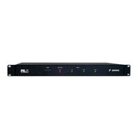
RLE Technologies F3400 User Manual (94 pages)
F-Series
Brand:
RLE Technologies
| Category:
Switch
| Size: 1 MB
Table of Contents
Copyright Notice
2
Revision History
2
Trademark Notices
2
Technical Support
3
Table of Contents
5
1 System Overview
13
Product Description
13
Front Panel Indicators and Controls
14
Figure 1.1 Front Panel Indicators and Controls
14
Terminal Block Designations
15
Table 1.1 Terminal Block Designations
15
Figure 1.2 Terminal Block Designations
17
Rear Panel Indicators
18
SW1 Switch Settings
18
Figure 1.3 Rear LED Indicator and Status
18
Figure 1.4 SW1 Switch Is on and SW2 Switch Is off
18
Table 1.2 Rear Panel Status Indicators
18
2 Getting Started
19
Installation
19
Communication
19
Set the F3400/F1000'S IP Address
19
Set the F3400/F1000'S IP Address Using the ARP and PING Commands
20
Obtain the Ethernet Address
20
Use the ARP Command
20
Use the PING Command
20
Troubleshooting the ARP/PING Commands
21
Set the F3400/F1000'S IP Address Using a Web Browser
21
Set the F3400/F1000'S IP Address Using an EIA232 Connection
22
Set the F3400/F1000'S IP Address Using a Telnet Connection
22
F3400/F1000 Wiring
23
Power Supply and Ground Connections
23
Figure 2.1 24 VDC Power Supply Connection
23
EIA232 COM1 Connection
24
RJ11 Phone Line Connection
24
Figure 2.2 EIA232 COM1 Connection
24
RJ45 Ethernet Connection
25
Figure 2.3 F3400/F1000 Ethernet Connection to a PC Using a Crossover Cable
25
Figure 2.4 F3400/F1000 Ethernet Connection to a PC on a Subnet
25
Relay K1 and K2 Connection
26
Figure 2.5 F3400/F1000 Relay Output Wiring Examples
26
3 F3400/F1000 Web Interface
27
F3400/F1000 Web Interface Overview
27
Main Menu
27
Figure 3.1 Example of F3400/F1000'S Main Menu
27
Historical Data
28
Alarm History
28
Figure 3.2 Example of the Alarm History Page
28
Event History
29
Figure 3.3 Example of the Event History Page
29
Digital Status History
30
Web User Access Log
30
Figure 3.4 Example of the Digital Status History Page
30
Figure 3.5 Example of Web User Access Log Page
30
Data History
31
Minute, Hour, and Day View
31
Figure 3.6 Example of the Data History Page
31
Figure 3.7 Day View Example
31
Data History Text Downloads
32
Server History
32
Figure 3.8 Example of the Data History Text Download Page
32
Figure 3.9 Example of the Server History Page
32
Server Status
33
Identity
33
Figure 3.10 Example of the Server Status Page
33
Figure 3.11 Example of the F3400/F1000 Identity Page
33
Web Links
34
Configuration
34
Figure 3.12 Example of the Web Links Display Page
34
Figure 3.13 Configuration Menu
34
4 Configuration Menu
35
Figure 4.1 Configuration Menu
35
Figure 4.2 Inputs Configuration Page
36
Inputs
36
Figure 4.3 Calculator Link
37
Figure 4.4 Relays Configuration Page
40
Relays
40
Figure 4.5 Schedules Configuration Menu
41
Schedules
41
Alarm Management
42
Figure 4.6 Alarm Management
42
Modem
43
Figure 4.7 Modem Configuration Page
43
Configure Phone Numbers
44
Figure 4.8 Phone Number Configuration Page
44
Figure 4.9 Configuring Web Links
46
Web Links
46
Egg/Nest
47
Falcon Links
47
Figure 4.10 Egg/Nest Configuration Page
47
Figure 4.11 Falcon Links Configuration Page
47
Figure 4.12 SNMP/SYSLOG Configuration Page
48
Snmp/Syslog
48
Modbus Interface
49
Figure 4.13 Modbus Interface Configuration
49
Figure 4.14 LD Unit Modbus Slave Configuration
50
LD Unit Modbus Slave Configuration
50
Figure 4.15 Modbus Register Data Log Page
51
Figure 4.16 Modbus Packet Log
51
Modbus Packet Log
51
Modbus Register Data Log
51
F-Series Modbus Slave Register Map
52
Reset Modbus Port
52
Table 4.1 Output Registers
52
Table 4.2 Status Flags (Registers 40201-40232)
52
Table 4.3 Status Flags (Registers 40401-40432)
52
Bacnet
53
Figure 4.17 Bacnet Configuration
53
Figure 4.18 Server Ping Configuration
54
Server Ping
54
Figure 4.19 System Configuration
55
System
55
Clock
56
Figure 4.20 Clock Configuration
56
Figure 4.21 Setting the Internet Protocol
56
Internet Protocol
56
Figure 4.22 User Administration Configuration
57
User Administration (Web Access)
57
Email
58
Figure 4.23 Email Configuration
58
Figure 4.24 Network Time Protocol Configuration
59
Network Time Protocol
59
Figure 4.25 Setting the Network Statistics
60
Figure 4.26 Flash Programs
60
Flash Program
60
Network Statistics
60
Figure 4.27 Product Registration Located at Www.rletech.com
61
Product Registration
61
5 EIA-232 Interface
63
Figure 5.1 Hyperterminal Connection Screen
63
Figure 5.2 Com1 Properties Screen
64
Flash Executable Code
64
Unit Start up
64
Main Menu
65
Table 5.1 Main Menu Commands
65
Main Configuration Menu - SC
66
Table 5.2 Main Configuration Menu (SC) Commands
66
IP Configuration Menu
67
Table 5.3 IP Configuration Menu Commands
67
Command Description
68
6 Remote Access
69
Remote Access Configuration (Modem Option)
69
7 Point-To-Point Protocol
71
Configuring the F3400/F1000
71
Configuring the PC
72
8 Upgrading Firmware and Managing Configuration Data
73
Upgrading F3400/F1000 Firmware
73
Upgrading F3400/F1000 Firmware Via TFTP Client
74
Updating F3400/F1000 Firmware Via the EIA232 COM1 Port (X-Modem)
75
Loading/Saving F3400/F1000 Configuration Data
76
Saving Configuration Data Via TFTP Client
76
Saving Configuration Data Via EIA232 COM1 Port (X-Modem)
76
Loading Configuration Data Via TFTP Client
77
Loading Configuration Data Via EIA232 COM1 Port (X-Modem)
77
A Analog Input 4-20Ma Reference Chart
79
Analog Input 4-20Ma Reference Chart
79
Table A.1 Analog Input 4-20Ma Reference Chart
79
F3400/F1000 Accessories Wiring
81
Figure B.1 T120D Temperature Sensors
81
Figure B.2 TH140 & TH140D Temperature/Humidity Sensors
81
B F3400/F1000 Accessories Wiring
82
Figure B.3 Dwyer Temperature/Humidity Sensors
82
Figure B.4 BAPI Temperature/Humidity Sensor
82
Figure B.5 SMK Smoke Detector, Photoelectric
82
Figure B.6 HD150 & HD150-2 Gas Sensors
83
Figure B.7 SD Spot Detectors
83
Figure B.8 PFM Power Fail Monitor
83
Configuring the Seahawk LD5100 as an Analog Input
84
Figure B.10Seahawk LD5100 Distance Read Leak Detection (4-20Ma)
84
Figure B.11Seahawk LDRA6, LD1000, and LD300 Leak Detection
84
Figure B.9 Seahawk LD5100/LD2000 Distance Read Leak Detection (Dry Contact)
84
100 C Alarm ID Reference Tables
87
Alarm ID Reference Tables
87
Analog Tables
87
Table C.1 Analog Alarm ID Reference Tables, Inputs 1-4
87
C Alarm ID Reference Tables
88
Thermistor Tables
88
Table C.2 Thermistor Alarm ID Reference Tables, Inputs 5-8
88
Digital Tables
89
Table C.3 Digital Alarm ID Reference Tables, Digital Inputs 5 through 32
89
Technical Specifications
91
Table D.1 Technical Specifications
91
D Technical Specifications
93
Advertisement
RLE Technologies F3400 Quick Start Manual (2 pages)
Brand:
RLE Technologies
| Category:
Measuring Instruments
| Size: 0 MB
Advertisement
Related Products
RLE Technologies F1000
RLE Technologies MONITORING F110
RLE Technologies FDS-Wi
RLE Technologies Falcon Wi-MGR
RLE Technologies Falcon FMS
RLE Technologies Categories
Measuring Instruments
Controller
Security Sensors
Gateway
Temperature Controller
More RLE Technologies Manuals
Login
Sign In
OR
Sign in with Facebook
Sign in with Google
Upload manual
Upload from disk
Upload from URL