Sign In
Upload
Manuals
Brands
RKI Instruments Manuals
Gas Detectors
725-101-P2-50
RKI Instruments 725-101-P2-50 Manuals
Manuals and User Guides for RKI Instruments 725-101-P2-50. We have
1
RKI Instruments 725-101-P2-50 manual available for free PDF download: Operator's Manual
RKI Instruments 725-101-P2-50 Operator's Manual (269 pages)
Brand:
RKI Instruments
| Category:
Gas Detectors
| Size: 3 MB
Table of Contents
Table of Contents
3
Chapter 1: Introduction
10
Overview
10
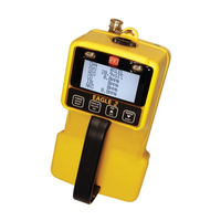
About the EAGLE 2
10
Specifications
12
About this Manual
13
Chapter 2: Description
14
Overview
14
Instrument Description
14
Case
16
Sensors
16
Lcd
17
Control Buttons
17
Printed Circuit Boards (Pcbs)
18
Alarm Leds
19
Infrared Communications Port
19
Buzzer
20
Battery Case & Batteries
20
Flow System
20
Standard Accessories
21
Shoulder Strap
21
Hose and Probe
21
Optional Accessories
23
Rechargeable Ni-MH Batteries
23
Battery Chargers
23
Optional Probes
24
External Dilution Fittings
26
Chapter 3: Operation
27
Overview
27
Start up
27
Turning on the EAGLE 2
27
Performing a Demand Zero
31
Turning off the EAGLE 2
32
Using the Battery Charger for Continuous Operation
32
Measuring Mode, Normal Operation
33
Monitoring an Area
33
Using Optional Sample Hoses
34
Using Exhaust Tubing
34
Combustible Gas Detection
34
Monitoring Combustible Gas in the PPM or %Volume Ranges
36
Measuring Mode, Alarms
38
Alarm Indications
38
Resetting and Silencing Alarms
39
Responding to Alarms
40
Display Mode
41
Tips for Using Display Mode
42
Peak Screen
42
Battery Voltage Screen
43
Gas Display Screen
43
Catalytic (LEL) Sensor Screen
44
Methane Elimination Mode Screen
44
Relative Response Screen
44
STEL Screen
46
TWA Screen
46
View Alarm Settings Screen
47
Select User ID Screen
48
Select Station ID Screen
49
Time in Operation Screen
50
Date/Time Screen
51
Data Logging Screen
51
Data Logging
52
Chapter 4: Calibration Mode
54
Overview
54
Calibration Supplies and Equipment
55
Entering Calibration Mode
56
Calibrating Using the Auto Calibration Method
56
Setting the Fresh Air Reading
56
Performing a Span Adjustment in Auto Calibration
58
Calibrating Using the Single Calibration Method
62
Setting the Fresh Air Reading
62
Performing a Span Adjustment in Single Calibration
63
Chapter 5: Maintenance
67
Overview
67
Troubleshooting
67
Replacing or Recharging the Batteries
69
Replacing the Batteries
69
Recharging the Ni-MH Batteries
70
Replacing the Hydrophobic Probe's Particle Filter and Hydrophobic Filter Disk
72
Replacing the Hydrophobic Filter
73
Replacing the Charcoal Filter
75
Checking the Combustible Gas Sensor's Condition
76
Replacing a Sensor
76
General Parts List
79
Appendix A: Calibrating with a Sample Bag
82
Overview
82
Calibration Supplies and Equipment
82
Entering Calibration Mode
83
Calibrating Using the Auto Calibration Method
84
Setting the Fresh Air Reading
84
Performing a Span Adjustment in Auto Calibration
85
Calibrating Using the Single Calibration Method
89
Setting the Fresh Air Reading
89
Performing a Span Adjustment in Single Calibration
90
Parts List
94
Appendix B: Setup Mode
95
Overview
95
Tips for Using Setup Mode
96
Using Setup Mode
96
Setting the Date and Time
97
Setting the Date Format
98
Setting the Battery Type
98
Configuring the Channels
99
Configuring the Combustible Gas
101
Setting the Catalytic Detection Units
105
Updating the Relative Response Setting
106
Updating the Alarm Point Settings
106
Updating the Alarm Latching Setting
108
Updating the Alarm Silence Setting
108
Turning the User/Station ID Function on or off
109
Updating the Autocal Values
109
Updating the Backlight Delay Setting
110
Updating the Auto Fresh Air Setting
110
Updating the Data Log Interval Setting
111
Updating the Data Log Overwrite Setting
111
Updating the Data Log Memory Setting
112
Updating the LCD Contrast Setting
112
Updating the Calibration Reminder Setting
113
Updating the Calibration Past Due Action Setting
113
Updating the Calibration Interval
114
Updating LC/BH Mode Setting
114
Setting the Bar Hole Measurement Time
115
Zero Follower Settings
115
Zero Suppression Settings
115
Updating the Confirmation Alert Setting
115
Turning the Password Function on or off
116
Restoring the Default Settings
117
Updating the Lunch Break Setting
118
Updating the Span Factor Setting
119
Updating the Language Setting
119
Exiting Setup Mode
120
Appendix C: Sub Pcbs
121
Overview
121
Description
121
Channel Setup and Sub Pcbs
122
Sub Pcbs and CONFIGURE CHANNELS
122
Sub Pcbs and CONFIGURE GASES
123
Appendix D: PID Sensors
125
Overview
125
Description
125
PID Sensor and Sensor Adapter
126
PID Sub PCB
126
PID Probe
127
Start up and Normal Operation
127
PID Relative Response Feature
128
PID Sensor Relative Response Screen in Display Mode
129
PID Calibration
131
Calibrating with a 4-Gas Cylinder and a PID Cylinder
131
Calibrating with a 5-Gas Cylinder
139
Maintenance
146
Troubleshooting
146
Cleaning the PID Sensor's Lamp
146
Replacing PID Sensor's Lamp
150
Replacing Electrode Stack
153
Replacing the PID Sensor
156
Configuring the PID Gas in Setup Mode
157
Parts List
162
Appendix E: ESM-01 Toxic Sensors
164
Overview
164
Description
164
Sensor
165
ESM-01 Sub PCB
165
Start up and Normal Operation
166
ESM-01 Calibration
166
Calibrating with a 4-Gas Cylinder and an ESM-01 Cylinder
166
Calibrating with a 5-Gas Cylinder
174
Maintenance
180
Replacing the ESM-01 Sensor
180
Replacing the H S Scrubber in the so and HCN Sensors
181
Parts List
183
Appendix F: TC Sensors
184
Overview
184
Description
184
TC Sensor
185
TC Sub PCB
185
Start up and Normal Operation
186
Catalytic (LEL) Sensor Screen
186
TC Calibration
187
Maintenance
193
Replacing the TC Sensor
193
Configuring the TC Gas in Setup Mode
195
Parts List
199
Appendix G: Infrared Carbon Dioxide Sensors
200
Overview
200
Description
200
Infrared Carbon Dioxide Sensor
201
Infrared Sub PCB
201
CO2 Scrubber
201
Start up and Normal Operation
202
Performing a Demand Zero for Carbon Dioxide Sensors
203
Infrared Carbon Dioxide Calibration
203
Maintenance
211
Replacing the IR CO Sensor or Changing Sensor Type
211
Parts List
213
Appendix H: Infrared Methane Sensors
214
Overview
214
Target Gases
214
Description
215
Infrared Methane Sensor
215
Infrared Sub PCB
216
Start up and Normal Operation
216
Detection Ranges
216
Catalytic (LEL) Sensor Screen
216
Infrared Methane Calibration
217
Maintenance
224
Replacing the IR Methane Sensor
224
Parts List
225
Appendix I: Infrared Hydrocarbon Sensor
226
Overview
226
Target Gases
226
Description
226
Infrared Hydrocarbon Sensor
227
Infrared Sub PCB
227
Start up and Normal Operation
227
0-100 %LEL/2.0-30.0 %Vol Autoranging
227
Catalytic (LEL) Sensor Screen
228
Infrared Hydrocarbon Calibration
228
Maintenance
235
Replacing the IR Hydrocarbon Sensor
235
Parts List
236
Appendix J: Methane Elimination Mode
237
Overview
237
Monitoring in Methane Elimination Mode
237
Calibration
240
Appendix K: Using the EAGLE 2 in Bar Hole Mode
241
Overview
241
Start Up, Bar Hole Mode
241
Turning on EAGLE 2, Bar Hole Mode
241
Performing a Demand Zero, Bar Hole Mode
245
Bar Hole Testing
246
Performing a Bar Hole Test
246
Turning off the EAGLE 2, Bar Hole Mode
248
Appendix L: Using the EAGLE 2 in Leak Check Mode
249
Overview
249
Start Up, Leak Check Mode
249
Turning on the EAGLE 2, Leak Check Mode
249
Performing a Demand Zero, Leak Check Mode
254
Leak Testing
254
Locating a Leak
254
Turning the Buzzer on and off in Leak Check Mode
255
Turning off the EAGLE 2, Leak Check Mode
255
Appendix M: EAGLE 2 Tank Tester Model
256
Description
256
Float Probe Assembly
257
Dilution Fitting (1:1)
257
Start up
258
Alarms
259
Calibration
260
Parts List
260
Appendix N: Using the EAGLE 2 in Inert Mode
261
Description
261
Alarms
261
Start up
263
Operation
265
Appendix O: Transformer Gas Tester Model
266
Description
266
Operation
266
Alarms
267
Parts List
267
Appendix P: Internal Dilution Models
268
Description
268
Calibration
268
Advertisement
Advertisement
Related Products
RKI Instruments 72-5103RK-01
RKI Instruments 72-5298RK
RKI Instruments 72-5385RK
RKI Instruments 72-5422RK
RKI Instruments 72-5414RK
RKI Instruments 72-5278RK
RKI Instruments 72-5309RK
RKI Instruments 72-5313RK
RKI Instruments 72-5269RK
RKI Instruments 72-5367RK
RKI Instruments Categories
Transmitter
Security Sensors
Gas Detectors
Measuring Instruments
Monitor
More RKI Instruments Manuals
Login
Sign In
OR
Sign in with Facebook
Sign in with Google
Upload manual
Upload from disk
Upload from URL