Riello RLS 38 Manuals
Manuals and User Guides for Riello RLS 38. We have 5 Riello RLS 38 manuals available for free PDF download: Installation, Use And Maintenance Instructions, Installation, Use And Maintenance Manual
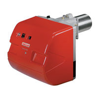
Riello RLS 38 Installation, Use And Maintenance Instructions (48 pages)
Dual fuel light-oil/gas burners Two-stage operation
Brand: Riello
|
Category: Indoor Fireplace
|
Size: 1 MB
Table of Contents
Advertisement
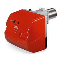
Riello RLS 38 Installation, Use And Maintenance Instructions (64 pages)
Dual fuel light oil/ gas burners
Table of Contents

Riello RLS 38 Installation, Use And Maintenance Instructions (48 pages)
Dual fuel gas oil/ gas burners
Table of Contents
Advertisement
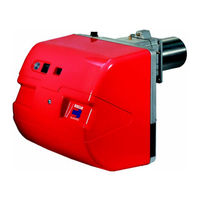
Riello RLS 38 Installation, Use And Maintenance Instructions (44 pages)
Forced draught gas burner
Brand: Riello
|
Category: Indoor Fireplace
|
Size: 1 MB
Table of Contents

Riello RLS 38 Installation, Use And Maintenance Manual (26 pages)
dual fuel gas/light oil burners
Table of Contents
Advertisement