Sign In
Upload
Manuals
Brands
RFL Electronics Manuals
Relays
GARD 8000
RFL Electronics GARD 8000 Manuals
Manuals and User Guides for RFL Electronics GARD 8000. We have
2
RFL Electronics GARD 8000 manuals available for free PDF download: Instruction Manual
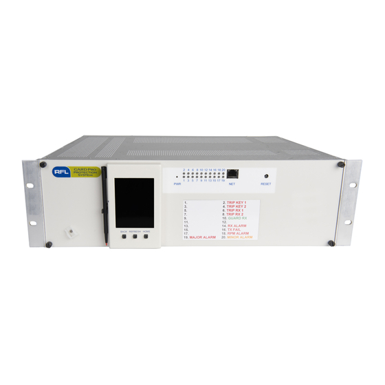
RFL Electronics GARD 8000 Instruction Manual (648 pages)
PROTECTIVE RELAY & COMMUNICATIONS SYSTEM
Brand:
RFL Electronics
| Category:
Relays
| Size: 14 MB
Table of Contents
Section 12. Audio Tone
17
Section 1. Product Information
23
Section 2. Applications
25
Figure 2-1. Web Bro Wser Interface Overview
26
Ga Rd 8000 a Rchitecture
27
Figure 2-2. GA RD 8000 3U Chassis Front and Rear View
28
Figure 2-4. GA RD 8000 Conceptual Design
30
Figure 2-5. Front and Rear of 3U Chassis
32
Figure 2-6. GA RD 8000 DC Connection Diagram, 3U Distance Relay Plus Teleprotection System
33
Ga Rd 8000 Base System
34
Figure 2-7. Alarm Configurat Ions
35
Figure 2-8. Antenna
36
Figure 2-9. Programmable Led's, 3U Chassis
38
Figure 2-10. Programmable Led's, 6U Chassis
39
Figure 2-11. Typical LED Color Configuration for a GA RD 8000 with a PLC FSK Module
40
Communication Interfa Ces
42
Figure 2-13. T1/ E1Drop and Insert and Terminal Pass Thru
44
System Sequence of Events Recording (Soe)
46
Teleprotection System
47
Distance Protection Termina L
48
Current Differential Protection
49
Aux Comm Unications Channel
50
Figure 2-14. Typical GA RD 8000 Aux Co Mmunication Channel Applicat Ion
51
Remote Service Cha Nnel
52
Section 3. Technica L Data
55
Communication Interfa Ces Specifications
57
Current Differentia L Specifications
59
Pow er Line Carrier Specifications
60
Specifications for the 9508 Rf Chassis (Option)
61
Ga Rd M Etering M Odule Specifications
62
Ga Rd Telem Etry T Ransm Itter M Odule Specifications
63
Section 4. Installat Ion a Nd Commissioning
65
M Ounting
66
Figure 4-1. Mounting Dimensions for GA RD 8000
67
Ventilation
68
Connections
69
Figure 4-2. Location of Protective Earth Stud
71
Figure 4-3. Location of TB1
72
Figure 4-4. Location of Synchronous Mu Lti-P Rotocol Interface
73
Figure 4-5. Pin-Outs RS-449, X.21, V.35
74
Figure 4-6. Pin-Outs G.703
75
Figure 4-8. Pin-Outs, RS-232
76
Figure 4-10. Terminal Block Connections, Metering Module
77
Table 4-3. GA RD 8000 Modules, General in Formation
79
Commissioning Procedures
80
Figure 4-12. Power Supply I/ O Module (Teleprotection Co Mmissioning)
82
Figure 4-13. GARD 8000 Controller Module (Teleprotection Co Mmissioning)
83
Table 4-4. Front Port Ethernet Led's
85
Figure 4-14. Power Supply I/ O Module (Audio-Tone Co Mmissioning)
95
Figure 4-15. GARD 8000 Controller Module (Audio-Tone Co Mmissioning)
96
Figure 4-16. PLC Analog Module Test Points
110
Figure 4-17. Location of 50W Power a Mp Lifie R
114
Figure 4-18. 50W Power a Mplifier Circuit Board
115
Figure 4-19. PLC Rear of 50W RF Chassis
116
Figure 4-20. GARD 8000 Controller Module (Co Mmissioning, Current Diff)
119
Figure 4-21. Current Diff. Relay Wiring
120
Section 5 August
141
Figure 5-2. Front View of the 6U Chassis Showing Location of the RJ-45 Port
142
Figure 5-3. Rear View of 6U Chassis Showing Location of RJ-45 (O R Fiber Optic) and RS-232 Ports
143
Figure 5-4. Front View of 3U Chassis Showing the Location of the RJ-45 Port
144
Figure 5-6. Co Mmunication Overview (Typical)
145
Ethernet a Ccess
146
Figure 5-8. GA RD Login Access
147
Figure 5-9. TCP/IP Address Setup
148
Table 5-3. Rear Ethernet Port Leds
149
Chassis Configuration Status Pa Ge
157
Figure 5-11. Typical Chassis Configuration Status Page for 6U Chassis
158
Front Pa Nel of System Displa y with Tps Module
159
Figure 5-13. Touch Screen Orientation
160
Figure 5-15. TSD LED Labels
161
Figure 5-16. Measured Values
162
Figure 5-17. Events Log (Soe's)
163
Figure 5-18. TSD Push Button Interface Configuration
164
Figure 5-19. TSD Push Button Interface
165
Passwords a Nd Security
166
Figure 5-22. Access Administration Page
167
Figure 5-23. W EB/FTP Server Ad Min Istration Page
169
Table 5-4. Security Levels
170
Figure 5-24. User Access Web Page
172
Figure 5-25. User Access Log
173
Rem Ote Service Channels
174
Figure 5-27. Remote Service Examp Le
175
Figure 5-28. Remote Service Channel, Co Mmunication Time Slot Configuration
176
Figure 5-29. Remote Service Channel, Set-Up GA RD (A)
177
Figure 5-30. Remote Service Channel, Set-Up GA RD (B)
178
Guidelines for Configuring a Pc for Ip Networks
179
Figure 5-31. Obtain an IP Address Automatically
180
Figure 5-33. Internet Protocol Version
181
Figure 5-34. Entering the IP Address
182
Figure 5-35. Local Area Connections Properties
183
Figure 5-36. Internet Protocol Properties/Ip Address
184
Section 7 April
185
Figure 6-1. Module Placement in GA RD 8000 3U Chassis
186
Figure 6-2. Module Placement in GA RD 8000 6U Chassis
187
Controller Module
188
Figure 6-3. Controls and Indicators Locator Drawing for Controller Module
189
Table 6-2. Controls and Indicators for the GA RD 8000 Controller Module
190
Table 6-3. Web Page, Controller Card, Status Color Codes
193
Displa y with Tps M Odule
194
Figure 6-5. Controls and Indicators Locator Drawing for Display with TPS Module
196
Table 6-4. Controls and Indicators for the GA RD 8000 Display with TPS Module
197
Digita L Tps Module
198
Audio Tone Tps Module
199
Table 6-6. Ju Mper Settings and Switch Function for the GA RD 8000 Audio Tone TPS Module
200
Pow er Line Carrier Modules
201
Table 6-8. PLC Analog Module Assembly Part Nu Mbers (500935)
202
Figure 6-8. PLC Digital Module
203
Table 6-10. Ju Mper Settings and Switch Function for the GA RD 8000 PLC Dig Ital Module
204
Figure 6-9. PLC Analog Module Top View
206
Figure 6-10. PLC Analog Module Panel View
207
System I/ O M Odules
210
Figure 6-12. GARD 8000 6U System I/O Modules , Rear Panel V Iews
211
Figure 6-13. GARD 8000 6U System I/O Module, Board V Iew Showing Ju Mper Locations
212
Figure 6-14. GARD 8000 3U System I/O Modules, Rear Panel Views
213
Figure 6-15. GARD 8000 3U System I/O Module, Board V Iew Showing Ju Mper Locations
214
Discrete I/O Base Module and I/O M Odules
215
Figure 6-17. Co Mponent Side of Input Unit (500805)
216
Figure 6-18. Top and Rear V Iews of Discrete I/ O Base Module
217
Figure 6-19. Co Mponent Side of Relay Output Unit (500815)
219
Figure 6-20. Top and Rear V Iew O F Discrete I/O Base Module
220
Comms I/ O Base Module and Comms M Odules
221
Table 6-15. Characteristics of GA RD 8000 Long Haul Fiber Units
222
Figure 6-21. Top and Front Views of Co Mms I/O Base Module
223
Pow er Supply M Odule
224
Table 6-18. GA RD Po Wer Supply Modules, General Informat Ion
225
Table 6-19. GA RD 8000 Po Wer Supply Specificat Ions
226
Figure 6-23. Power Supply I/ O Module, Rear Panel View
227
Figure 6-24. Optional Power Supply I/ O Module, G.703 Interface Rear Panel View
228
Ga Rd System a Larms
229
Figure 6-25. a Larm Configurations Web Page
231
Table 6-22. GA RD Module Level Alarms
232
Midplane
234
Figure 6-26. Current Limit I/O Module Terminal Block Connections
235
Telem Etry Tra Nsmitter M Odule
236
Section 7. Chassis Configuration Settings
237
M Odule Settings
238
Figure 7-2. Chassis Configuration Settings Web Page for 6U Chassis with Redundancy
239
Figure 7-3. Input Card in Slot #2 Rear Left Web Page
240
Figure 7-4. Chassis Configuration Settings Web Page
242
Figure 7-5. Relay Output Card in Slot #4 Rear Left Web Page
243
Figure 7-6. Chassis Configuration Settings Web Page
245
Figure 7-7. Co Mmunications System Configuration Web Page
246
Figure 7-8. Co Mmunications System Status
250
Figure 7-9. Digital Interface Status
251
Figure 7-10. Chassis Configuration Settings Web Page
254
Figure 7-11. Teleprotection Channel Configuration at Slot #1 Front Web Page
255
Figure 7-12. Teleprotection Channel Configuration at Slot #1 Front Web Page
256
Figure 7-13. TPS Channel 1 Slot #1 Front Web Page
257
Figure 7-14. TPS Status
260
Figure 7-15. Chassis Configuration Settings Web Page (96-Bit System)
263
Figure 7-17. Chassis Configuration Settings Web Page
266
Figure 7-18. Co Mmun Ications System Configuration Web Page
267
Figure 7-19. Co Mmun Ications Time Slot Configurat Ion Web Page
268
Figure 7-20. Co Mmun Ications Time Slot Configurat Ion Web Page (96 -Bit)
269
Figure 7-21. 96-Bit Telep Rotection Web Page
270
Figure 7-22. Async Co Mms Configuration
273
Table 7-1. Timeslot Baud Rate
274
Table 7-2. Character Formats
275
Figure 7-24. Async Co Mms Channel Settings
276
Figure 7-25. Async Co Mms Status Web Page
277
Figure 7-26. Co Mmun Ications Time Slot Configurat Ion Web Page for Async Co Mms Module
278
Figure 7-27. Chassis Configuration Settings Web Page
279
Figure 7-28. Audio Tone Configuration Web Page
280
Figure 7-29. Audio Tone General Settings Web Page
281
Figure 7-30. Audio Tone Channel 1 Settings Web Page
283
Table 7-3. Reco Mmended Security Timer Settings
286
Figure 7-31. Audio Tone Status Web Page
287
Figure 7-32. Audio Tone, General Status Web Page
288
Figure 7-33. Audio Tone, Channel Status Web Page
290
Figure 7-34. Audio Tone, Modem Status Web Page
292
Figure 7-35. Chassis Configuration Settings Web Page
294
Figure 7-36. Power Line Carrier Configuration Web Page
295
Figure 7-37. Power Line Carrier General Settings Web Page
296
Figure 7-38. Receiver Operating Range and Dynamic Range
301
Figure 7-39. Power Line Carrier Checkback Settings (On-Off Only) Web Page
302
Figure 7-40. PLC Status Web Page
304
Figure 7-41. PLC General Status Web Page
305
Figure 7-42. PLC Counter Values Web Page
308
Figure 7-43. Telemetry Transmitter Module Settings
310
Table 7-5. Telemetry Analog Gain
311
Figure 7-44. Telemetry Transmitter Module Status
312
System la Bels and Triggers
313
Figure 7-46. System Configuration Web Page
314
Table 7-6. Clock Quality Level Indication
315
Figure 7-47. Time Settings Web Page
316
Figure 7-48. System Labels and Triggers – LED Logic Assignments
317
Figure 7-50. Input Card in Slot#2 Rear Left Web Page
319
Figure 7-51. System Labels and Triggers – SOE Triggers and Labels
320
Figure 7-53. Sequence of Events, Text Download
323
Figure 7-54. System Counters Web Page
324
Figure 7-55. System Labels and Triggers – Logic Bit Labels
325
Figure 7-57. System Labels and Triggers – Edit HMI Labels
327
A Larm Configuration
329
Figure 7-60. a Larm Configurations Web Page
330
Table 7-7. Bit Error Rate Threshold Settings
332
File Operations
334
Figure 7-62. Send File to GA RD 8000 Web Page
335
Figure 7-64. Save File to PC Web Page
339
System Logic Configuration
342
Figure 7-66. Input Mapping Web Page (Typical)
343
Figure 7-67. Input Mapping Web Page (Typical)
344
Figure 7-68. System Logic Configuration Web Page
345
Figure 7-69. Output Mapping Web Page (Typical)
346
Figure 7-70. System Logic Configuration Web Page
347
Figure 7-71. Option Settings Web Page (Typical)
348
Figure 7-72. System Logic Configuration Web Page
349
Figure 7-73. Timer Settings Web Page (Typical)
350
Section 9 March
351
Figure 8-2. Three Input and Gate
352
Figure 8-4. Three Input or Gate
353
Figure 8-6. Inverter Gate
354
Figure 8-7. Latch
355
Figure 8-8. Toggle Gate
356
Figure 8-9. Timer
357
Figure 8-10. Buffer
358
Logic Configurat Ion
359
Figure 8-11. System Logic Configuration Web Page
360
Figure 8-12. Input Mapping Web Page
361
Figure 8-13. Output Mapping Web Page
362
Figure 8-14. Option Settings Web Page
363
Figure 8-15. System Timer Setting Web Page
364
Default Tps Logic
365
Table 8-9. Option Settings
366
Default Tps & Distance Logic
367
Table 8-12. Output Mapping
368
Table 8-13. Opt Ion Settings
369
Table 8-14. Default Logic Timers
370
Logic Design Reserved I/O
371
Table 8-17. Logic Bit Assignment
372
M Etering M Odule Logic Bus Pla Cem Ent
373
Section 9. Teleprotection
375
Figure 9-1. Permissive Underreaching Transfer Trip
376
Figure 9-3. Direct Transfer Trip
377
Figure 9-4. Direct Ional Co Mparison Blocking
378
Teleprotection Settings
379
Section 15 April
381
Fsk Operation
383
Figure 10-1. GARD 8000 PLC FSK Block Diagram
384
Figure 10-2. M Inimu M Channel Spacing (FSK)
385
On-Off Operation
386
Figure 10-3. GARD 8000 PLC On/Off Block Diagram
388
Setting the Transmit Ca Rrier Frequency Range
389
Figure 10-4. GARD PLC Analog Module Carrier Frequency Range Jumper Settings
390
Table 10-5. TX Filter Ju Mper Settings (Part Number Series 500935)
391
Tx Level M Eter Ca Libration
392
Reflected Power M Eter Ca Libration
393
Carrier Level Indicator
395
Figure 10-5. PLC Analog Module, Carrier Level Indicator Modes - Ju Mpers
396
Figure 10-6. CLI Meter, Front Panel Mounting on 3U Chassis
397
Figure 10-7. PLC Dig Ital Module (500455-1)
398
Using the Rfl 9508 Rf Chassis with the Ga Rd 8000 Plc
399
Figure 10-9. Front View of the 9508 RF Chassis Showing Module Locations
400
Figure 10-10. 9508 RF Chassis Block Diagram
401
Figure 10-12. 9508 RF Chassis Power a Mp Lifier, Power Supply
402
Figure 10-14. TX Filter, Top View
403
Figure 10-15. Balance Board
404
Figure 10-16. Line Board
405
Figure 10-18. RFL 9508 RX Filter Board
407
Figure 10-19. RFL 9508 RX Connection Board
408
Figure 10-21. RFL 9508 RF Mother Board, Rear View
409
Table 10-12. TB-1 Terminal Assignments
410
Figure 10-22. Module Placement in a Typical 50W 9508 RF Chassis (Top View)
411
Figure 10-23. Cable Connections in the RF Chassis
413
Figure 10-24. Module Placement in the Au Xiliary 3U Chassis for the 100W System
414
Figure 10-25. Location of 50W Power a Mplifier Module
415
Table 10-16. Function of Ju Mpers, Connectors and Potentiometers on Power a Mp
416
Table 10-17. Function of DIP Switches SW1 and SW2 on Power a Mp Board
417
Figure 10-27. Location of Ju Mpers on the Tx Filter, PC Board 107828 -2
418
Table 10-18. Tx Filter Setup Ju Mpers
419
Figure 10-28. Location of Ju Mpers on the Tx Filter, PC Board 107828-1
420
Figure 10-29. Location of Ju Mpers on the Balance Board
421
Figure 10-30. Location of Ju Mpers on the Line Board
422
Table 10-20. Line Board, Setup Ju Mpers and Switch Sett Ings
423
Figure 10-31. Attenuator Board, Location of SW1
424
Figure 10-32. Location of Ju Mpers on the RX Filter Board, Showing Jumper Groupings
425
Figure 10-33. Rear Panel W Iring of a Typical GA RD 8000 with a 50W 9508 RF Chassis
427
Figure 10-34. Rear Panel W Iring of a Typical GA RD 8000 with a 100W 9508 RF Chassis
428
Figure 10-35. Schemat IC, GA RD 8000 PLC Analog Module, B-500934-K 30-392 Khz, 50 Oh M (Sheet 1 O F 4)
429
Figure 10-36. Default Logic, GA RD 8000 On-Off PLC
433
Figure 10-37. Default Logic, GA RD 8000 FSK PLC
434
Section 16 February
435
Input M Odule Test
436
Output Module T Est
440
Comm Unications Modules
444
Figure 11-4. Digital Interface Web Page
445
Figure 11-5. Manual Loopback
448
Figure 11-6. Local Loopback
449
Figure 11-7. Remote Loopback
450
Figure 11-8. C37.94 Web Page
452
Figure 11-9. Local Loopback
454
Figure 11-10. Manual Loopback
455
Figure 11-11. G.703 Web Page
457
Figure 11-12. Manual Loopback
460
Figure 11-14. Long Haul Fiber Web Page
462
Figure 11-15. Local Loopback
464
Figure 11-16. Manual Loopback
465
Figure 11-17. Manual Loopback
466
Figure 11-18. T1/ E1 Web Page
469
Figure 11-19. Manual Loopback
471
Audio Tone Module Test
473
Plc M Odule Test
478
Figure 11-23. PLC Module Testing Web Page
479
Current Differientia L Rela y Test
482
Figure 11-24. System Testing, Current Diff
483
Figure 12-3. Audio Tone Logic Block Diagram, Channel 1 Used as a Modem
493
Figure 12-4. Audio Tone Logic Block Diagram, Dual 1 2 Dual 3 4
494
Figure 12-5. Audio Tone Logic Block Diagram, Simp Le
495
Section 13. Current Differential Rela y
496
Configuration
497
Figure 13-1 Location of Front Panel Leds
498
Figure 13-2 Front and Rear View of 3U Chassis with Current Differential Module (Typical)
499
Figure 13-3. Current Differential Rear Connections
500
Figure 13-5 File Operations, Cu Rrent Differential
501
Figure 13-7. Ho Me Page
502
Figure 13-9. Input Mapping Webpage
503
Figure 13-10. Output Mapping Webpage
504
Figure 13-11. Current Differential Inputs, Schematic Diagram
505
Figure 13-12. Current Differential Outputs, Schematic Diagram
506
Rela y Settings
508
Figure 13-14. Current Differential Relay Configurat Ion
509
Figure 13-15. Current Differential Relay General Settings
511
Figure 13-16. Current Differential Relay Co Mms Settings
514
Figure 13-17. Current Differential Relay Primary Settings
515
Figure 13-18. Current Differential Relay Backup Settings
519
Figure 13-19. Current Differential Relay SOE Settings
524
Figure 13-20. Current Differential Relay Oscillography Settings
527
Current Differential Rela y Status
529
Figure 13-22. Current Differential Relay General Status Webpage
530
Figure 13-23. Current Differential Relay Phase Status Webpage
533
Figure 13-24. Current Differential Relay Co Mmunicat Ions Status Webpage
535
Figure 13-25. Current Differential Relay Transferred Status Bits Webpage
537
Figure 13-26. Current Differential Metering and Status Webpage
538
Figure 13-27. Current Differential Relay Last Trip Webpage
540
Figure 13-28. Current Differential Relay Last Trip Webpage
541
Applications
542
Figure 13-30. Fau Lt Detectors
543
Figure 13-31. Peak Change Fault Detector
544
Figure 13-32. Pu Lse Width Fault Detector
545
Figure 13-34. Po Larity Change Fault Detector
546
Figure 13-35. Dual Breaker – Restraint Current
547
Figure 13-36. Charge Co Mparison Current Differential Relaying Princip Le
548
Figure 13-37. Three Terminal Application
549
Figure 13-38 Operate Level Slope Characteristic
551
Figure 13-39. High Set Trip for an External Fau Lt Condition
554
Figure 13-41 USA Moderately Inverse TOC Characteristic
558
Figure 13-42 USA Inverse TOC Characteristic
559
Figure 13-43 USA very Inverse TOC Characteristic
560
Figure 13-44 USA Extremely Inverse TOC Characteristic
561
Figure 13-45 IEC Standard Type a TOC Characteristic
562
Figure 13-46 IEC Standard Type B TOC Characteristic
563
Figure 13-47 IEC Standard Type C TOC Character
564
Figure 13-48 Recloser Block Logic
570
Figure 13-49 Three Pole Tripping Logic
571
Figure 13-50 Single Pole Tripping Logic
572
Sequence of Events and Oscillogra Phy
573
Table 13-2 Maximu M Nu Mber of Oscillography Records
574
Section 14. Ethernet Tps M Odule
582
Insta Llation
583
Figure 14-3 Rear Connections
584
Figure 14-4 Ethernet TPS Module, Fuse Protection
585
Configuration
586
Figure 14-7 Ethernet TPS Module, General Settings
587
Figure 14-8 Ethernet TPS Module, Retransmission Timer Settings
590
Figure 14-9 Ethernet TPS Module, Retransmission Timer Settings
591
Figure 14-10 Ethernet TPS Module, Logic B It Configuration
592
Figure 14-11 Ethernet TPS Module, Status
594
Section 14 April
595
Section 15. Ga Rd M Etering M Odule
597
Web Pa Ge Set-Up
598
Figure 15-2. Metering Module Configuration Settings
599
Figure 15-4. Metering Module – General Settings
600
Figure 15-5. Current Thresholds Settings
601
Figure 15-6. Frequency Thresholds Settings
603
Figure 15-7. Vo Ltage Thresholds Settings
605
Figure 15-8. Power Thresholds Settings
607
Figure 15-9. Metering Module Status
609
Figure 15-11. Metering Module Threshold Status
610
Figure 15-12. Metering Module Analog Values
612
Section 16. Ga Rd Dnp3 Configuration and Snmp Tra P a Gent
613
Rs-485 Connections
614
Dnp3 Web Page Set-Up
615
Figure 16-4. DNP Settings
616
Figure 16-5. Deadband Reporting
617
Figure 16-7. DNP Scale, Offset, Alias Web Page
618
Figure 16-8. Customer a Lias Entry (Typical)
619
Figure 16-9. Configuring Math Points
620
Figure 16-10. Po Int List Settings Web Page (Typical)
622
Figure 16-11. Po Int List Web Page
624
Dnp V3.00 Device Profile Docum Ent
625
Snmp Trap a Gent
629
Figure 16-13. SNMP Trap Receivers
630
Figure 16-14. Enabling the Trap Receiver M IB
631
Rfl Snmp Mib File
632
Procedure for Loa Ding Mib's to the Ga Rd 8000
633
Section 17 August
638
Section 18. Application Notes
644
Section 19. Accessory Equipm Ent
646
Advertisement
RFL Electronics GARD 8000 Instruction Manual (270 pages)
DISTANCE RELAY MODULE
Brand:
RFL Electronics
| Category:
Control Unit
| Size: 9 MB
Table of Contents
Table of Contents
3
Table of Figures
5
Warning Labels and Safety Summary
9
Section 1. Product Information
15
Section 2. General Description and Overview
17
Description
17
General Overview
17
Section 3. System Specifications
19
Figure 4-1. Three Phase Operating Times
23
Figure 4-2. Two Phase Operating Times
23
Section 4. Distance Relay Operating Times
23
Figure 4-3. Single Phase Operating Times
24
Section 5. Standards and Type Tests
25
Section 6. Configuration
27
System Configuration Overview
27
Hardware Configuration
27
Figure 6-1. Front and Rear Views of 3U Chassis with Distance Relay (Typical)
28
Figure 6-2. External Connections for the 3U Chassis
28
Figure 6-3. Input Mapping Web Page
29
Figure 6-4. Output Mapping Web Page
30
Figure 6-5. Distance Relay Rear Connections
30
Figure 6-6. AC Schematic for GARD 8000 Distance Protection
31
Figure 6-7. Distance Relay Inputs, Schematic Diagram
32
Figure 6-8. Distance Relay Outputs, Schematic Diagram
33
Logic Signals Available from the Distance Protection Module
34
Section 7. Distance Relay Settings
35
General Settings
35
GARD 8000 Distance Relay RFL Electronics Inc
35
Line Protection System Settings
36
Distance Elements
41
Current Elements
49
Recloser and Sync Check
58
Breaker Failure
61
Voltage Elements
62
Fault Recorder (Dfr)
64
Oscillography Mask
65
Soe Mask
67
Section 8. Distance Relay Setting Examples
71
Gard 8000 21L Setting Examples - Stepped Distance
71
Figure 8-1. Trip Mask Enable and Element Enable (Stepped Distance)
73
Gard 8000 21L Setting Examples - Directional Comparison Blocking
83
Figure 8-2. Trip Mask Enable and Element Enable (Directional Comparison Blocking)
84
Figure 8-3. Directional Comparison Blocking (DCB) Distance Relay Scheme
97
Figure 8-4. Directional Comparison Blocking (DCB) Directional Overcurrent Scheme
98
Section 9. Description of Operation
109
Distance Elements
109
Table 9-1. MHO Characteristic
110
Table 9-2. MHO Characteristic Table Definitions
110
Figure 9-1. MHO Phase-Ground Characteristic (I)
111
Figure 9-2. Mho Phase-Ground Characteristic (II)
112
Table 9-3. MHO Phase-Ground Characteristic Definitions
112
Figure 9-3. Phase-Phase Mho Characteristic (I)
113
Table 9-4. Phase-Phase Mho Characteristic Definitions
113
Table 9-5. Quadrilateral Characteristics
114
Table 9-6. Quadrilateral Characteristics Definitions
114
Figure 9-4. Reactance Characteristic (I)
115
Figure 9-5. Reactance Characteristic (II)
116
Figure 9-6. Directional Unit
117
Table 9-7. Directional Unit
117
Table 9-8. Directional Unit Definitions
117
Figure 9-7. Resistive Blinder
118
Table 9-9. Resistive Limiter Characteristic
119
Table 9-10. Resistive Limiter Characteristic Definitions
119
Figure 9-8. AG Distance Element Operational Logic
120
Figure 9-9. AB Distance Element Operational Logic
121
Table 9-11. Supervision Elements
122
Table 9-12. Supervision Elements Definitions
122
Non-Pilot and Pilot Schemes
123
Figure 9-10. Zone Logic
123
Figure 9-11. Stepped Distance Logic
123
Figure 9-12. Zone 1 Extension
124
Figure 9-13. Permissive Underreach Transfer Trip (PUTT)
125
Figure 9-14. PUTT
126
Figure 9-15. Direct Transfer Trip (DTT)
127
Figure 9-16. Permissive Overreach Transfer Trip (POTT)
127
Figure 9-17. Permissive Overreach
128
Figure 9-18. Directional Comparison Blocking with Directional Carrier TX
129
Figure 9-19. Directional Comparison Blocking
130
Figure 9-20. Directional Comparison Unblocking
131
Figure 9-21. Directional Comparison Unblocking Diagram
132
Figure 9-22. Transient Block Logic
133
Figure 9-23. Transient Block Logic
133
Figure 9-24. Transient Block Logic Diagram
133
Figure 9-25. Weak Infeed Logic
135
Phase Selector
136
Figure 9-26. Phase Selector
136
Fault Detector
137
Loss-Of-Potential Block
137
Figure 9-27. Loss-Of-Potential Block
137
Open Pole Logic
138
Figure 9-28. Open Pole Logic with Individual 52B Inputs
138
Close-Into-Fault
139
Figure 9-29. Open Pole Logic with One Common 52B Input
139
Figure 9-30. Close-Into-Fault Block Diagram
140
Load Enchroachment
141
Power Swing Block Unit
141
Figure 9-31. Load Encroachment Characteristic
141
Figure 9-32. Power Swing Unit
142
Remote Open Breaker Detection
143
Figure 9-33. Open Breaker Detector
144
Overcurrent Elements
145
Figure 9-34. Minimum Operating Time for Time Overcurrent Curve
147
Figure 9-35. Minimum Operating Time When Set Fixed Time Exceeds Curve Time Delay at 1.5 X Pick-Up
147
Figure 9-36. ANSI Moderately Inverse
148
Figure 9-37. ANSI Inverse
149
Figure 9-38. ANSI very Inverse
150
Figure 9-39. ANSI Extremely Inverse
151
Figure 9-40. ANSI Short Time
152
Figure 9-41. Inverse (IEC)
153
Figure 9-42. IEC very Inverse
154
Figure 9-43. IEC Extremely Inverse
155
Figure 9-44. IEC Long Inverse
156
Figure 9-45. IEC Short Inverse
157
Figure 9-46. IEEE Moderately Inverse
158
Figure 9-47. IEEE very Inverse
159
Figure 9-48. IEEE Extremely Inverse
160
Figure 9-49. RI Inverse
161
Directional Units
163
Table 9-13. Phase Directional Measurement
163
Figure 9-50. Vector Diagram for the Phase Directional Unit
164
Table 9-14. Phase Directional Element
164
Figure 9-51. Application Example
165
Figure 9-52. Ground Directional Characteristic with Voltage Polarization
166
Table 9-15. Directional Ground Element
166
Figure 9-53. Zero Sequence Network for a Forward Fault
167
Figure 9-54. Negative Sequence Network for a Forward Fault
168
Directional Overcurrent Pilot Schemes
169
Stub Bus Protection
170
Figure 9-55. Directional Overcurrent DCB Scheme
170
Figure 9-56. Stub Bus Protection
170
Broken Conductor (Phase Unbalance) Unit (46)
171
Thermal Image Unit
171
Figure 9-57. Thermal Time Constant
172
Figure 9-58. Thermal Image Characteristic Time Curves
172
Voltage Units
173
Figure 9-59. Block Diagram for Phase Undervoltage Units
174
Figure 9-60. Block Diagram for Phase Overvoltage Units
175
Frequency Units (81)
176
Figure 9-61. Rate of Change of Frequency
177
Breaker Failure Relay Unit
178
Figure 9-62. Breaker Failure Relay
179
Synch Check Unit
180
Table 9-18. Angular Compensation
180
Pole Discordance
182
Figure 9-63. Synchro and Energizing Check Logic
182
Figure 9-64. Pole Discordance Logic
182
Trip Logic
183
Figure 9-65. Distance Module Trip Logic
183
Reclosing Unit
184
Figure 9-66. Reclose Initiate Logic
185
Figure 9-67. Reclosing Mode
186
Figure 9-68. Recloser Lock-Out Operation
187
Figure 9-69. Recloser Lock-Out Operation
188
Breaker Supervision Functions
192
Series Compensated Applications
193
Section 10. Sequence of Events Reports and Fault Recording
195
Measured Values, Trip Status, Sequence of Events and Fault Records
195
Measured Values and Trip Status
195
Figure 10-1. Distance Measured Values
195
Figure 10-2. Distance Metering
196
Figure 10-3. Distance Protection Unit Status
197
Figure 10-4. Distance Recloser Status
198
Figure 10-5. Distance Status at Last Trip
199
Figure 10-6. Distance SOE Screen
200
Figure 10-7. Distance SOE Detail Screen
201
Figure 10-8. Distance Fault Record
202
Figure 10-9. Distance Fault Record Details (Part 1 of 3)
203
Table 10-1. Oscillographic Record
206
Fault Locator
207
Section 11. Distance Relay Logic Programming
209
Overview
209
Factory Default Programming
209
Inputs
209
Outputs
212
Zivercom
214
Distance Module Complete Signal List
232
Section 12. Distance Relay Commissioning
251
Equipment Requirements
251
Power Connections
252
Boot-Up Progress
252
Figure 12-1. GARD 8000 Controller Module (Commissioning, Distance Relay)
252
Ethernet Connection
253
Logic/Software Verification
253
Distance Relay Wiring Verification
254
Figure 12-2. AC Schematic for GARD Distance Protection
254
Distance Relay Configuration Settings Verification
255
Figure 12-3. Distance Relay I/O Connections (Commissioning)
255
Nominal Voltage and Current Verification
256
Input/Output Mapping Verification
257
Led Logic Assignments Verification
259
System Configuration Verification
259
Distance Relay Functional Testing
260
Section 13. Index
267
Section 14. Application Notes
269
Advertisement
Related Products
RFL Electronics Categories
Multiplexer
Media Converter
Network Router
Switch
Computer Hardware
More RFL Electronics Manuals
Login
Sign In
OR
Sign in with Facebook
Sign in with Google
Upload manual
Upload from disk
Upload from URL