Table of Contents
Advertisement
GARD 8000 DISTANCE RELAY MODULE
(This manual should always be used in conjunction with the GARD 8000 System Instructional Manual)
The information in this manual is proprietary and confidential to RFL Electronics Inc. Any reproduction
or distribution of this manual, in whole or part, is expressly prohibited, unless written permission is given
by RFL Electronics Inc.
This manual has been compiled and checked for accuracy. The information in this manual does not
constitute a warranty of performance. RFL Electronics Inc. reserves the right to revise this manual and
make changes to its contents from time to time. We assume no liability for losses incurred as a result of
out-of-date or incorrect information contained in this manual.
GARD 8000 Distance Relay
April 1, 2010
INSTRUCTION MANUAL
NOTICE
RFL Electronics Inc.
353 Powerville Road ● Boonton Twp., NJ 07005-9151 USA
Tel: 973.334.3100 ● Fax: 973.334.3863
Email:
sales@rflelect.com
Publication Number MC8000DIS
Printed in U.S.A.
April 1, 2010
●
www.rflelect.com
i
RFL Electronics Inc.
973.334.3100
Advertisement
Table of Contents

Related Manuals for RFL Electronics GARD 8000

Summary of Contents for RFL Electronics GARD 8000
- Page 1 INSTRUCTION MANUAL GARD 8000 DISTANCE RELAY MODULE (This manual should always be used in conjunction with the GARD 8000 System Instructional Manual) NOTICE The information in this manual is proprietary and confidential to RFL Electronics Inc. Any reproduction or distribution of this manual, in whole or part, is expressly prohibited, unless written permission is given by RFL Electronics Inc.
- Page 2 WARRANTY The GARD 8000 Distance Relay comes with a ten-year warranty from date of shipment for replacement of any part, which fails during normal operation. RFL will repair or, at its option, replace components that prove to be defective at no cost to the Customer.
-
Page 3: Table Of Contents
7.10 SOE MASK ....................................7-33 SECTION 8. DISTANCE RELAY SETTING EXAMPLES ..................8-1 8.1 GARD 8000 21L SETTING EXAMPLES – STEPPED DISTANCE ..................... 8-1 8.2 GARD 8000 21L SETTING EXAMPLES – DIRECTIONAL COMPARISON BLOCKING............8-13 SECTION 9. DESCRIPTION OF OPERATION ....................9-1 9.1 DISTANCE ELEMENTS................................ - Page 4 12.10 LED LOGIC ASSIGNMENTS VERIFICATION ........................12-9 12.11 SYSTEM CONFIGURATION VERIFICATION ........................12-9 12.12 DISTANCE RELAY FUNCTIONAL TESTING........................12-10 SECTION 13. INDEX ............................13-1 SECTION 14. APPLICATION NOTES ....................... 14-1 GARD 8000 Distance Relay RFL Electronics Inc. April 1, 2010 973.334.3100...
-
Page 5: Table Of Figures
Figure 6-4. Output Mapping web page ..........................6-4 Figure 6-5. Distance relay rear connections .......................... 6-4 Figure 6-6. AC Schematic for GARD 8000 Distance Protection .................... 6-5 Figure 6-7. Distance Relay Inputs, schematic diagram......................6-6 Figure 6-8. Distance Relay Outputs, schematic diagram ....................... 6-7 Figure 8-1. - Page 6 Figure 10-8. Distance Fault Record ............................. 10-8 Figure 10-9. Distance Fault Record Details (Part 1 of 3) ..................... 10-9 Figure 12-1. GARD 8000 Controller Module (Commissioning, Distance Relay) ..............12-2 Figure 12-2. AC Schematic for GARD Distance Protection ....................12-4 Figure 12-3.
- Page 7 Table 10-1. Oscillographic Record............................. 10-12 Related Documentation RFL can provide the end user with a GARD 8000 System Emulator on a separate CD; this is not provided with the documentation package. The GARD 8000 System Emulator can be downloaded from the RFL website;...
- Page 8 Customer Resource Center The RFL Electronics Inc. "On-line Customer Resource Center" has been created to provide customers with "real-time" information necessary to keep RFL equipment operating optimally. The Resource Center contains Application Notes, Service Notices, Product Bulletins, Software Downloads, Software Upgrades, Technical Product Manuals and Sales Brochures, in a convenient and easy-to-use location on our web site.
-
Page 9: Warning Labels And Safety Summary
3U GARD Unit shown, position of labels on 6U unit similar CAUTION FOR YOUR SAFETY THE INSTALLATION, OPERATION AND MAINTENANCE OF THIS EQUIPMENT SHOULD ONLY BE PERFORMED BY QUALIFIED PERSONS ONLY. GARD 8000 Distance Relay RFL Electronics Inc. April 1, 2010 973.334.3100... - Page 10 Failure to comply with these precautions, or with specific warnings elsewhere in this manual, violates safety standards of design, manufacture, and intended use of this product. RFL Electronics Inc. assumes no liability for failure to comply with these requirements.
- Page 11 AND FLOOR MATS, AND LEAVE MODULES IN THEIR ANTI-STATIC BAGS UNTIL THEY ARE READY TO BE INSTALLED. WARNING! YOUR GARD 8000 TERMINAL MAY BE EQUIPPED WITH FIBER OPTIC INPUT/OUTPUT MODULES THAT HAVE FIBER OPTIC EMITTER HEADS. FIBER OPTIC EMITTER HEADS USE A LASER LIGHT SOURCE THAT...
- Page 12 LIST OF EFFECTIVE PAGES When revisions are made to the GARD 8000 Distance Relay Instruction Manual, the entire section where revisions were made is replaced. For the edition of this manual dated April 1, 2010 the sections are dated as...
- Page 13 New Section 8 added (Distance Relay Setting Examples). 8-1-09 Remaining sections moved up one section. Section 13 added (Application Notes). 4-1-10 Addition of new section for Logic Programming (Section 11). Remaining sections moved up one. GARD 8000 Distance Relay RFL Electronics Inc. April 1, 2010 xiii 973.334.3100...
- Page 14 This page intentionally left blank GARD 8000 Distance Relay RFL Electronics Inc. April 1, 2010 973.334.3100...
-
Page 15: Section 1. Product Information
Product Information SECTION 1. PRODUCT INFORMATION Please go to the next page for the following Data Sheet: GARD 8000 Distance Relay Module GARD 8000 Distance Relay RFL Electronics Inc. January, 2009 973.334.3100... - Page 16 Product Information This page intentionally left blank GARD 8000 Distance Relay RFL Electronics Inc. January, 2009 973.334.3100...
-
Page 17: Section 2. General Description And Overview
These can use the same channel as the distance protection pilot logic, or separate channels. The GARD 8000 Distance Module can be configured for single pole tripping and logic for series compensated line applications is included. The GARD 8000 Distance Module recloser function provides up to 3 reclose attempts. The recloser can be supervised by the built-in synchronism check function, or by the use of an external device. - Page 18 General Description and Overview This page intentionally left blank GARD 8000 Distance Relay RFL Electronics Inc. March 1, 2009 973.334.3100...
-
Page 19: Section 3. System Specifications
±1 % of setting or ±20 ms (whichever is greater) Inverse Time: Class 2 (E = 2 %) (UNE 21-136, CEI 255 and ANSI C37.60) Repeatability Operating Time: < 2% or 25 ms (whichever is greater) GARD 8000 Distance Relay RFL Electronics Inc. March 1, 2009 973.334.3100... - Page 20 Definite time Inverse Very inverse Extremely inverse Long time inverse Short time inverse Inverse + maximum time Very inverse + maximum time Extremely inverse + maximum time User defined GARD 8000 Distance Relay RFL Electronics Inc. March 1, 2009 973.334.3100...
- Page 21 Slip frequency 0.005 - 2.00 Hz Time delay 0.05 - 300.00 s Recloser No of shots 1 - 3 Dead-time 0.1 - 300 s Reset time 0.05 - 300 s GARD 8000 Distance Relay RFL Electronics Inc. March 1, 2009 973.334.3100...
- Page 22 System Specifications This page intentionally left blank GARD 8000 Distance Relay RFL Electronics Inc. March 1, 2009 973.334.3100...
-
Page 23: Section 4. Distance Relay Operating Times
Three Phase SIR=0.1 SIR=1 SIR=10 % of set reach Figure 4-1. Three Phase Operating Times Phase-Phase SIR=0.1 SIR=1.0 SIR=10 % of set reach Figure 4-2. Two Phase Operating Times GARD 8000 Distance Relay RFL Electronics Inc. March 1, 2009 973.334.3100... -
Page 24: Figure 4-3. Single Phase Operating Times
Distance Relay Operation Times Single Phase SIR=0.1 SIR=1 SIR=10 % of set reach Figure 4-3. Single Phase Operating Times GARD 8000 Distance Relay RFL Electronics Inc. March 1, 2009 973.334.3100... -
Page 25: Section 5. Standards And Type Tests
±8 kV ± 10% In air ±15 kV ± 10% IEC-61000-4-5 (UNE 61000-4-5) Surge Immunity Test (1.2/50µs – 8/20µs) Between conductors: 4 kV Between conductors and ground: 4 kV GARD 8000 Distance Relay RFL Electronics Inc. March 1, 2009 973.334.3100... - Page 26 Surge Capacity IEC 60255-21-1 Class I Vibration Test (sinusoidal) IEC 60255-21-2 Class I Mechanical Shock and Bump Test IEC 60529 / IEC 60068-2-75 (IP30 / IK07) External Protection Levels GARD 8000 Distance Relay RFL Electronics Inc. March 1, 2009 973.334.3100...
-
Page 27: Section 6. Configuration
6.2 HARDWARE CONFIGURATION A GARD 8000 System can be built up with Functional Modules as required for a specific application, with a selectable number of inputs, outputs and communications interfaces. Each GARD 8000 is delivered with chassis drawings, showing the actual hardware and the factory default configuration. -
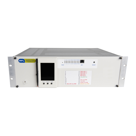
Page 28: Figure 6-1. Front And Rear Views Of 3U Chassis With Distance Relay (Typical)
IN 3 Rear Slot 2 OUT 6 IN 4 OUT 7 IN 7 IN 5 IN 8 OUT 8 IN 6 Figure 6-2. External connections for the 3U chassis GARD 8000 Distance Relay RFL Electronics Inc. March 1, 2009 973.334.3100... -
Page 29: Figure 6-3. Input Mapping Web Page
Configuration The inputs (Slot 2) and outputs (Slot 4) are user configurable and is setup using a web page: Figure 6-3. Input Mapping web page GARD 8000 Distance Relay RFL Electronics Inc. March 1, 2009 973.334.3100... -
Page 30: Figure 6-4. Output Mapping Web Page
21 20 19 18 17 16 15 14 13 12 11 IPol- VSyn- IPN- IPN+ IPol+ Chassis Chassis Chassis Chassis Chassis Chassis VSyn+ Figure 6-5. Distance relay rear connections GARD 8000 Distance Relay RFL Electronics Inc. March 1, 2009 973.334.3100... -
Page 31: Figure 6-6. Ac Schematic For Gard 8000 Distance Protection
GARD 8000 Slot 3 V sync check I sensitive neutral or current polarizing I neutral from parallel line for fault locator Figure 6-6. AC Schematic for GARD 8000 Distance Protection GARD 8000 Distance Relay RFL Electronics Inc. March 1, 2009 973.334.3100... -
Page 32: Figure 6-7. Distance Relay Inputs, Schematic Diagram
To fully understand what the inputs and outputs are doing in the system logic, the actual System Logic Diagram should be consulted. This is supplied at the rear of the GARD 8000 manual and is also available for download or viewing from the GARD file operations menu. -
Page 33: Figure 6-8. Distance Relay Outputs, Schematic Diagram
The GARD 8000 System provides 20 user configurable LED’s. Each LED is tri-colored; red, yellow, and green. Each color can individually represent a logic function. In case more than one color is active, red will override yellow and green and yellow will override green. -
Page 34: Logic Signals Available From The Distance Protection Module
The distance relay module creates a number of logic signals from its measuring element and protection logic. The GARD 8000 System logic uses these signals to perform trip and pilot scheme operations. The default logic is bringing out some of the available signals, but all of the signals shown in the logic diagrams in the GARD System Instruction Manual are available for custom logic. -
Page 35: Section 7. Distance Relay Settings
(then set to 0). It can also be set to a value corresponding to estimated breaking current at the time GARD 8000 is put into service, enabling a ‘start’ value for the counter other than 0. 0 - 99999.99 kA²... -
Page 36: Line Protection System Settings
Zero sequence impedance magnitude for the local source, in secondary ohms. Used for the fault locator. As the source impedance value may differ depending on system configuration, use the typical value. 0.01 - 100 0.01 1.25 GARD 8000 Distance Relay RFL Electronics Inc. July 21, 2009 973.334.3100... - Page 37 In & Out In & Out Length units Determines display of fault locator calculation in kilometers or miles, when parameter ‘Fault Locator Units’ is set to ‘Length Kilometers Units’. Miles Miles GARD 8000 Distance Relay RFL Electronics Inc. July 21, 2009 973.334.3100...
- Page 38 Turns mutual coupling compensation ON or OFF. For mutual coupling, the neutral ct current from the parallel line needs to No - Yes be wired into the GARD 8000 relay. Pickup report This setting determines whether fault records should be triggered from pick-up of any element (YES) or following a trip only (NO).
- Page 39 Enables trip by Ground Overvoltage, step 2. Enable Disable Disable - 81-1 Underfrequency Enables trip by Underfrequency, step 1. Enable Disable Disable - 81-2 Underfrequency Enables trip by Underfrequency, step 2. Enable Disable GARD 8000 Distance Relay RFL Electronics Inc. July 21, 2009 973.334.3100...
- Page 40 81-2 Rate-of-change of frequency Enables trip by Rate-of-change of Frequency, step 2. Enable Disable Disable - 81-3 Rate-of-change of frequency Enables trip by Rate-of-change of Frequency, step 3. Enable Disable GARD 8000 Distance Relay RFL Electronics Inc. July 21, 2009 973.334.3100...
-
Page 41: Distance Elements
0 - 300 0.01 0.25s Zone 3 enable Enable operation of Zone 3 distance No – Yes Reverse Zone 3 direction Zone 3 measuring direction, forward or reverse. Forward Forward GARD 8000 Distance Relay RFL Electronics Inc. July 21, 2009 973.334.3100... - Page 42 ‘Reactance’ or ‘Reactance OR Mho’ should be used. OR MHO Reactance, Phase characteristic Selection of mho, reactance (quadrilateral), reactance AND mho, Mho, reactance OR mho the phase distance elements. Reactance and MHO, Reactance or GARD 8000 Distance Relay RFL Electronics Inc. July 21, 2009 973.334.3100...
- Page 43 Sets the time delay for Directional Comparison Blocking (DCB) trip signal. This is the amount of time the forward pilot zone will wait to receive a blocking carrier signal before trip is released. 0 - 200 GARD 8000 Distance Relay RFL Electronics Inc. July 21, 2009 973.334.3100...
- Page 44 (ECHO+TRIP) or no weak infeed logic (None) for the ECHO+TRI None overcurrent directional comparison pilot schemes. 67 transient block enable Enable Transient Block Logic for the overcurrent directional comparison pilot schemes. No - Yes GARD 8000 Distance Relay RFL Electronics Inc. July 21, 2009 7-10 973.334.3100...
- Page 45 0.05 Power swing condition reset time Reset time for the power swing condition following a swing locus moving outside the outer (external) blinder. 0.02 - 1 0.002 0.05 GARD 8000 Distance Relay RFL Electronics Inc. July 21, 2009 7-11 973.334.3100...
- Page 46 Stub but pickup 0.10 - 150 0.01 Pickup current threshold for stub bus trip. Stub bus time delay 0 - 100 0.01 Trip time delay for stub bus trip. GARD 8000 Distance Relay RFL Electronics Inc. July 21, 2009 7-12 973.334.3100...
- Page 47 0 - 300 0.01 81M-1 Dropout Time Drop-out time delay for overfrequency, step 1 0 - 300 0.01 81M-2 Overfrequency enable Enables overfrequency, step 2 No - Yes GARD 8000 Distance Relay RFL Electronics Inc. July 21, 2009 7-13 973.334.3100...
- Page 48 Enables rate-of-change of frequency, step 2 No - Yes 81D-2 ROC underfrequency pickup Pickup threshold for underfrequency for the rate-of-change of frequency element, step 2 40 - 70 0.01 GARD 8000 Distance Relay RFL Electronics Inc. July 21, 2009 7-14 973.334.3100...
-
Page 49: Current Elements
67 transient block coordination time This is a timer setting for transient block logic when the directional overcurrent elements (50P and/or 50Q/G) are used in a permissive pilot scheme. 0 – 30 GARD 8000 Distance Relay RFL Electronics Inc. July 21, 2009 7-15 973.334.3100... - Page 50 0.01 51P-1 Time delay Sets the minimum time delay for the curves with Time Limit 0.05 - 300 0.01 0.05 (TL) for the phase timeovercurrent element, step 1 GARD 8000 Distance Relay RFL Electronics Inc. July 21, 2009 7-16 973.334.3100...
- Page 51 Short Time Inv. IEC Inverse IEC Minimum Time (TL) Very Inverse IEC Minimum Time (TL) Extr. Inverse IEC Minimum Time (TL) Long Time Inv. IEC Minimum Time (TL) GARD 8000 Distance Relay RFL Electronics Inc. July 21, 2009 7-17 973.334.3100...
- Page 52 Selection to use directional element or Zone 2 for torque control of the instantaneous ground overcurrent element, step 3 51G-1 Ground timeovercurrent enable Enable ground timeovercurrent element, step 1 No - Yes GARD 8000 Distance Relay RFL Electronics Inc. July 21, 2009 7-18 973.334.3100...
- Page 53 Selection to use directional element or Zone 2 for torque control of the ground timeovercurrent element, step 3 51G-3 Torque control Directional control of ground timeovercurrent element, step 3 Forward Reverse GARD 8000 Distance Relay RFL Electronics Inc. July 21, 2009 7-19 973.334.3100...
- Page 54 Pickup level for instantaneous negative sequence overcurrent element, step 2 0.25 - 150 0.01 50Q-2 Time delay Time delay for instantaneous negative sequence overcurrent element, step 2 0 - 300 0.01 GARD 8000 Distance Relay RFL Electronics Inc. July 21, 2009 7-20 973.334.3100...
- Page 55 Sets the time/current characteristic for the negative sequence curve timeovercurrent element, step 2 selection Definite below) Time 51Q-2 Time dial Sets the time dial for the selected curve 0.05 - 10 0.01 GARD 8000 Distance Relay RFL Electronics Inc. July 21, 2009 7-21 973.334.3100...
- Page 56 Extr. Inverse IEEE Minimum Time (TL) Mod. Inverse ANSI Inverse ANSI Very Inverse ANSI Extr. Inverse ANSI Short Time Inv. ANSI Mod. Inverse ANSI Minimum Time (TL) Inverse ANSI Minimum Time (TL) GARD 8000 Distance Relay RFL Electronics Inc. July 21, 2009 7-22 973.334.3100...
- Page 57 49 Thermal memory enable If thermal memory is set to Yes, the function retains the last calculated thermal level in memory and uses this as start level when the GARD 8000 is put back into service. No - Yes 49 Reset threshold 50 - 100 Thermal image reset level in % of alarm level.
-
Page 58: Recloser And Sync Check
Recloser reset time following closing of the circuit breaker. 0.05 - 300 0.01 Security Time for manual close Recloser reset time following manual closing of the circuit breaker. 0.05 - 300 0.01 GARD 8000 Distance Relay RFL Electronics Inc. July 21, 2009 7-24 973.334.3100... - Page 59 Enable reclose initiate from negative sequence instantaneous Disable - overcurrent trips, Step 3 Enable Disable 51Q-1 RI Enable reclose initiate from negative sequence time overcurrent Disable - trips, Step 1 Enable Disable GARD 8000 Distance Relay RFL Electronics Inc. July 21, 2009 7-25 973.334.3100...
- Page 60 Synch Check Delay 0 - 300 0.01 Sets delay time for synchro-check function LOP Synch Check Block No - Yes Enables block of synchro-check function for loss-of-potential conditions GARD 8000 Distance Relay RFL Electronics Inc. July 21, 2009 7-26 973.334.3100...
-
Page 61: Breaker Failure
Minimum current level for line charging current. When the measured current is below this value, the breaker pole is determined to be open. 0 - 5 0.01 0.75 GARD 8000 Distance Relay RFL Electronics Inc. July 21, 2009 7-27 973.334.3100... -
Page 62: Voltage Elements
(AND) or in parallel (OR) 27-2 Phase Undervoltage Enable Enables phase undervoltage element, step 2 No - Yes 27-2 Pickup Pickup level for phase undervoltage, step 2 10 - 300 0.01 GARD 8000 Distance Relay RFL Electronics Inc. July 21, 2009 7-28 973.334.3100... - Page 63 101 - 150 59P Drop-Out Ratio Drop-out ratio for the phase overvoltage elements 50 - 99 59G Drop-Out Ratio Drop-out ratio for the ground overvoltage elements 50 - 99 GARD 8000 Distance Relay RFL Electronics Inc. July 21, 2009 7-29 973.334.3100...
-
Page 64: Fault Recorder (Dfr)
No - Yes IPOL Enables recording of analog channel current polarizing input No - Yes IGPAR No - Yes Enables recording of analog channel neutral current from parallel line GARD 8000 Distance Relay RFL Electronics Inc. July 21, 2009 7-30 973.334.3100... -
Page 65: Oscillography Mask
Phase overvoltage, step 1 59P-2 Phase overvoltage, step 2 No - Yes 59P-3 Phase overvoltage, step 3 No - Yes 59G-1 Ground overvoltage, step 1 No - Yes GARD 8000 Distance Relay RFL Electronics Inc. July 21, 2009 7-31 973.334.3100... - Page 66 Zone 3 ground element Pickup No - Yes Z4 phase pickup Zone 4 phase element Pickup No - Yes Z4 ground pickup Zone 4 ground element Pickup No - Yes GARD 8000 Distance Relay RFL Electronics Inc. July 21, 2009 7-32 973.334.3100...
-
Page 67: Soe Mask
CA Z1 pickup No - Yes BC Z4 pickup No - Yes BC Z3 pickup No - Yes BC Z2 pickup No - Yes BC Z1 pickup No - Yes GARD 8000 Distance Relay RFL Electronics Inc. July 21, 2009 7-33 973.334.3100... - Page 68 51Q-1 pickup No - Yes A 51P-2 pickup No - Yes B 51P-2 pickup No - Yes C 51P-2 pickup No - Yes 51G-2 pickup No - Yes GARD 8000 Distance Relay RFL Electronics Inc. July 21, 2009 7-34 973.334.3100...
- Page 69 No - Yes C 59P-2 trip No - Yes Three phase 59P-2 trip No - Yes A 59P-3 trip No - Yes B 59P-3 trip No - Yes GARD 8000 Distance Relay RFL Electronics Inc. July 21, 2009 7-35 973.334.3100...
- Page 70 No - Yes Z2 fault No - Yes Z3 fault No - Yes Z4 fault No - Yes Z1-P pickup No - Yes Z1-G pickup No - Yes GARD 8000 Distance Relay RFL Electronics Inc. July 21, 2009 7-36 973.334.3100...
-
Page 71: Section 8. Distance Relay Setting Examples
Distance Relay Setting Examples SECTION 8. DISTANCE RELAY SETTING EXAMPLES 8.1 GARD 8000 21L SETTING EXAMPLES – STEPPED DISTANCE 8.1.1 LINE Nominal voltage 230 kV Nominal current Frequency 60 Hz Line length 54 miles Positive sequence Z1L Line impedance (primary ohms) 41.33@85 degrees... - Page 72 Current transformer ratio for the CT on a parallel line used for mutual coupling compensation for the fault locator. Excessive Trips 1 - 40 Maximum number of breaker trips during a half hour interval. Performed by the breaker monitoring function. GARD 8000 Distance Relay RFL Electronics Inc. August 1, 2009 973.334.3100...
-
Page 73: Figure 8-1. Trip Mask Enable And Element Enable (Stepped Distance)
Settings Enable Phase Units Z 2 Zone 2 phase timer Enable Ground Units Z 2 Zone 2 ground timer Figure 8-1. Trip Mask Enable and Element Enable (Stepped Distance) GARD 8000 Distance Relay RFL Electronics Inc. August 1, 2009 973.334.3100... - Page 74 Positive sequence impedance angle for the local source, in degrees. Used for the fault locator. As the source impedance value may differ depending on system configuration, use the typical value. 5 - 90 GARD 8000 Distance Relay RFL Electronics Inc. August 1, 2009 973.334.3100...
- Page 75 Determines if fault location should be calculated and displayed for faults on the protected line only (In) or for all faults that are detected by the distance relay (In & Out) In & Out In & Out GARD 8000 Distance Relay RFL Electronics Inc. August 1, 2009 973.334.3100...
- Page 76 Turns mutual coupling compensation ON or OFF. For mutual coupling, the neutral ct current from the parallel line needs to be No - Yes wired into the GARD 8000 relay. Pick Up Report This setting determines whether fault records should be triggered from pick-up of any element (YES) or following a trip only (NO).
- Page 77 Enables trip by Ground Overvoltage, step 1. Enable Disable 59G-2 Disable - Enables trip by Ground Overvoltage, step 2. Enable Disable 81 UNDFREQ1 Disable - Enables trip by Underfrequency, step 1. Enable Disable GARD 8000 Distance Relay RFL Electronics Inc. August 1, 2009 973.334.3100...
- Page 78 Time delay = 800 ms (0.8 s) Zone 4 reach (reverse, used for indication only in this stepped distance scheme) 50% of ZL1 = 0.5 · 4.13 = 2.07 GARD 8000 Distance Relay RFL Electronics Inc. August 1, 2009 973.334.3100...
- Page 79 0.01 Zone 2 ground timer Zone 2 ground elements time delay 0 - 300 0.01 Zone 2 phase timer Zone 2 phase elements time delay 0 - 300 0.01 GARD 8000 Distance Relay RFL Electronics Inc. August 1, 2009 973.334.3100...
- Page 80 Zone 4 ground timer Zone 4 ground elements time delay 0 - 300 0.01 Zone 4 phase timer Zone 4 phase elements time delay 0 - 300 0.01 GARD 8000 Distance Relay RFL Electronics Inc. August 1, 2009 8-10 973.334.3100...
- Page 81 Recommended setting is 2 cycles. 2 - 80 Cycles Voltage Threshold Voltage threshold for the memory polarization. When the measured voltage is below the set threshold, memory is used. 0.1 – 5 GARD 8000 Distance Relay RFL Electronics Inc. August 1, 2009 8-11 973.334.3100...
- Page 82 (lower setting of the current supervision element) than the forward elements to ensure proper coordination. 0.20 - 7.5 0.01 5.34 49 Thermal Img. Enable Enables the thermal image function No - Yes GARD 8000 Distance Relay RFL Electronics Inc. August 1, 2009 8-12 973.334.3100...
-
Page 83: Gard 8000 21L Setting Examples - Directional Comparison Blocking
49 Thermal Memory If thermal memory is set to Yes, the function retains the last calculated thermal level in memory and uses this as start level when the GARD 8000 is put back into service. No - Yes 49 Reset Threshold Thermal image reset level in % of alarm level. -
Page 84: Figure 8-2. Trip Mask Enable And Element Enable (Directional Comparison Blocking)
Phase Units Z 2 Zone 2 phase timer Enable Ground Units Z 2 Zone 2 ground timer Figure 8-2. Trip Mask Enable and Element Enable (Directional Comparison Blocking) GARD 8000 Distance Relay RFL Electronics Inc. August 1, 2009 8-14 973.334.3100... - Page 85 Positive sequence impedance angle for the local source, in degrees. Used for the fault locator. As the source impedance value may differ depending on system configuration, use the typical value. 5 - 90 GARD 8000 Distance Relay RFL Electronics Inc. August 1, 2009 8-15 973.334.3100...
- Page 86 ‘Length Units’. % of Length % of Length Line Length Total line length in kilometers or miles, as set for the parameter ‘Length Units’. 0 - 400 0.01 GARD 8000 Distance Relay RFL Electronics Inc. August 1, 2009 8-16 973.334.3100...
- Page 87 Mut Coupl. Comp. Enable Turns mutual coupling compensation ON or OFF. For mutual coupling, the neutral ct current from the parallel line needs to be wired into the GARD 8000 relay. No - Yes Pick Up Report This setting determines whether fault records should be triggered from pick-up of any element (YES) or following a trip only (NO).
- Page 88 Enable Disable 51Q-2 Disable - Enables trip by Negative Sequence Timeovercurrent, step 2. Enable Disable 51Q-3 Disable - Enables trip by Negative Sequence Timeovercurrent, step 3. Enable Disable GARD 8000 Distance Relay RFL Electronics Inc. August 1, 2009 8-18 973.334.3100...
- Page 89 Zone 2 will ensure high speed pilot operation for all types of faults on the line. The increased margin for Zone 4 will ensure high speed blocking of the remote end for faults behind the local terminal. GARD 8000 Distance Relay RFL Electronics Inc.
- Page 90 Zone 2 reach (forward pilot zone) 120% of ZL1 = 1.2 · 4.13 = 4.96 Zone 4 reach (reverse pilot zone) 50% of ZL1 = 0.5 · 4.13 = 2.07 GARD 8000 Distance Relay RFL Electronics Inc. August 1, 2009 8-20...
- Page 91 Zone 2 ground timer Zone 2 ground elements time delay 0 - 300 0.01 Zone 2 phase timer Zone 2 phase elements time delay 0 - 300 0.01 GARD 8000 Distance Relay RFL Electronics Inc. August 1, 2009 8-21 973.334.3100...
- Page 92 Zone 4 ground timer Zone 4 ground elements time delay 0 - 300 0.01 Zone 4 phase timer Zone 4 phase elements time delay 0 - 300 0.01 GARD 8000 Distance Relay RFL Electronics Inc. August 1, 2009 8-22 973.334.3100...
- Page 93 (for Zone 4) are set more sensitive and a 10% margin is suggested instead of the 20%. The reverse elements are consequently set at 4.90 A for our example. GARD 8000 Distance Relay RFL Electronics Inc. August 1, 2009 8-23 973.334.3100...
- Page 94 0.50 - 300 0.01 0.50 49 Max. Sust. Curr. Maximum allowed continuous load current on the line 1 - 12.5 49 Alarm Level Thermal image alarm level 50 - 100 GARD 8000 Distance Relay RFL Electronics Inc. August 1, 2009 8-24 973.334.3100...
- Page 95 49 Thermal Memory If thermal memory is set to Yes, the function retains the last calculated thermal level in memory and uses this as start level when the GARD 8000 is put back into service. No - Yes 49 Reset Threshold Thermal image reset level in % of alarm level.
- Page 96 A more sensitive 50G-1 setting may be required when coordinating with a remote E/M scheme. As the operating time of E/M relays are very setting (tap) dependent, settings are typically determined by end- to-end testing. GARD 8000 Distance Relay RFL Electronics Inc. August 1, 2009 8-26 973.334.3100...
-
Page 97: Figure 8-3. Directional Comparison Blocking (Dcb) Distance Relay Scheme
50P-1 Phase B Fast carrier start 50P-1 Phase C 50G-1 Ground Block pilot trip Out-of-step Block Enable OSB pilot Figure 8-3. Directional Comparison Blocking (DCB) Distance Relay Scheme GARD 8000 Distance Relay RFL Electronics Inc. August 1, 2009 8-27 973.334.3100... -
Page 98: Figure 8-4. Directional Comparison Blocking (Dcb) Directional Overcurrent Scheme
Carrier stop is also issued by the forward 50G-2 (67G-2) and/or the forward 50Q-2 (67Q-2) elements, but not until the DCB 67 delay time has timed out. GARD 8000 Distance Relay RFL Electronics Inc. August 1, 2009 8-28 973.334.3100... - Page 99 PLC directly and does not use the distance relay logic to perform this function. Hence, there is no setting associated with it in the distance relay; just input mapping required in the GARD “System Logic Configuration”. GARD 8000 Distance Relay RFL Electronics Inc. August 1, 2009 8-29 973.334.3100...
- Page 100 (DCB) only and enables to select Carrier Start from non-directional phase and ground overcurrent elements, in addition to the reverse blocking zone. The 50P-1, 50G-1 elements are utilized for this function. No - Yes GARD 8000 Distance Relay RFL Electronics Inc. August 1, 2009 8-30 973.334.3100...
- Page 101 2) Use zero sequence only. Then the 50G-1 element should be set for the 21 DCB scheme. If Fast carrier start is NOT used, no coordination is required and all 50 elements are set based on 67 DCB only. GARD 8000 Distance Relay RFL Electronics Inc. August 1, 2009 8-31 973.334.3100...
- Page 102 Pick-up level for phase timeovercurrent element, step 1 0.10 - 125 0.01 (see time curve 51P-1 Time Curve Sets the time/current characteristic for phase timeovercurrent selection Definite element, step 1 below) Time GARD 8000 Distance Relay RFL Electronics Inc. August 1, 2009 8-32 973.334.3100...
- Page 103 Directional control of phase timeovercurrent element, step 3 Reverse 51P-3 Torque Control Type Selection to use directional element or Zone 2 for torque control of the phase timeovercurrent element, step 3 GARD 8000 Distance Relay RFL Electronics Inc. August 1, 2009 8-33 973.334.3100...
- Page 104 3 Enable timeovercurrent ground (51G-1) Enable ground timeovercurrent element, step 1 No - Yes 51G-1 Pick-Up Pick-up level for ground timeovercurrent element, step 1 0.600 - 125 0.01 GARD 8000 Distance Relay RFL Electronics Inc. August 1, 2009 8-34 973.334.3100...
- Page 105 0.01 51G-3 Time Delay Sets the minimum time delay for the curves with Time Limit (TL) for the ground timeovercurrent element, step 3 0.05 - 300 0.01 0.05 GARD 8000 Distance Relay RFL Electronics Inc. August 1, 2009 8-35 973.334.3100...
- Page 106 Recommended setting for Minimum voltage is 1 V and for Voltage Compensation 0. The 67G Characteristic angle should be set equal to the local zero sequence source impedance angle (Z0SL). In our example Z0SL = 86 degrees. GARD 8000 Distance Relay RFL Electronics Inc. August 1, 2009 8-36 973.334.3100...
- Page 107 Characteristic angle 67Q should be set equal to the local source negative sequence angle (which may be equal to the source positive sequence angle Z1SL, e.g. 86 degrees in our example). GARD 8000 Distance Relay RFL Electronics Inc. August 1, 2009 8-37 973.334.3100...
- Page 108 Distance Relay Setting Examples This page intentionally left blank GARD 8000 Distance Relay RFL Electronics Inc. August 1, 2009 8-38 973.334.3100...
-
Page 109: Section 9. Description Of Operation
9.1.1 MHO CHARACTERISTIC The GARD 8000 Mho characteristic is polarized by the positive sequence voltage of the corresponding phase. This polarization gives the following characteristic, similar to cross-polarization: • Variable: The Mho circle always includes the origin, and the diameter is a function of the source impedance. -
Page 110: Table 9-1. Mho Characteristic
This effect enables tripping for close in faults with very low voltage. This displacement has no effect on the directional characteristic. For a reverse fault, the mho characteristic is displaced in the forward direction. GARD 8000 Distance Relay RFL Electronics Inc. August 1, 2009... -
Page 111: Figure 9-1. Mho Phase-Ground Characteristic (I)
MHO characteristic. The diameter of the characteristic is increased by the impedance: ⋅ − Figure 9-2 shows a ground fault Mho characteristic for a reverse fault. This characteristic demonstrates a displacement that is defined by the vector: ⋅ − GARD 8000 Distance Relay RFL Electronics Inc. August 1, 2009 973.334.3100... -
Page 112: Figure 9-2. Mho Phase-Ground Characteristic (Ii)
B and C. Positive sequence fault current Phase A voltage. The same measurement is being made for phase B and C. Polarizing voltage. Positive sequence voltage, referenced to the faulted phase. GARD 8000 Distance Relay RFL Electronics Inc. August 1, 2009 973.334.3100... -
Page 113: Figure 9-3. Phase-Phase Mho Characteristic (I)
Positive sequence phase to phase current ph-ph1 Phase to phase load current load Phase to phase voltage ph-ph Polarizing voltage. Positive sequence voltage for the ph-ph corresponding phases, directly or from memory buffer GARD 8000 Distance Relay RFL Electronics Inc. August 1, 2009 973.334.3100... -
Page 114: Table 9-5. Quadrilateral Characteristics
Description of Operation 9.1.2 QUADRILATERAL CHARACTERISTIC The GARD 8000 uses a load compensated Quadrilateral characteristic, polarized with the negative sequence current of the corresponding phase, eliminating over- and under-reach due to the remote-end infeed current’s effect on the fault impedance. This compensation is equivalent to a tilt in the characteristic, which is defined as tilt angle. -
Page 115: Figure 9-4. Reactance Characteristic (I)
Rotation of the Reactance characteristic (polarized by negative sequence current) compensates for the voltage drop produced by the fault impedance (as seen by the relay), avoiding both overreach and underreach. GARD 8000 Distance Relay RFL Electronics Inc. August 1, 2009... -
Page 116: Figure 9-5. Reactance Characteristic (Ii)
Angle gamma is calculated by the relay from the line and source impedances. Phase current Equivalent current: Ieq=IF+I0(k0-1) Phase voltage Ground fault resistance Current through ground fault resistance Set reach GARD 8000 Distance Relay RFL Electronics Inc. August 1, 2009 973.334.3100... -
Page 117: Figure 9-6. Directional Unit
Phase currents Iab, Ibc, Ica Phase-phase currents (Ia-Ib), (Ib-Ic), (Ic-Ia) Va1, Vb1, Vc1 Positive sequence voltage, referenced to each phase Vab1M, Vbc1M, Vca1M Positive sequence memory (when applicable) voltage, phase-phase GARD 8000 Distance Relay RFL Electronics Inc. August 1, 2009 973.334.3100... -
Page 118: Figure 9-7. Resistive Blinder
9.1.4 RESISTIVE BLINDER Figure 9-7. Resistive Blinder The GARD 8000 quadrilateral element is provided with six resistive limiters, one for ach type of fault, with independent reach settings for each zone. The reach of the resistive limiter for phase-to-ground and phase-to-phase faults are independent from each other. The characteristic is polarized by the equivalent current of the corresponding phase;... -
Page 119: Table 9-9. Resistive Limiter Characteristic
Resistive reach for phase-to-phase faults corresponding to zone n θ Positive sequence reach impedance angle corresponding to zone n θ Loop impedance angle for zone n: θ θ − ∠ − ∠ Ieqn GARD 8000 Distance Relay RFL Electronics Inc. August 1, 2009 9-11 973.334.3100... -
Page 120: Figure 9-8. Ag Distance Element Operational Logic
ZONE n (n_AG) AG ELEMENT PICKUP PHASE LAG ENABLE POLE B OPEN (PB_A) SETTING POLE C OPEN (PC_A) FUSE FAILURE BLOCKING (BLQ_FF) LOAD ENCROACHMENT ACTIVATION (DEL) Figure 9-8. AG Distance Element Operational Logic GARD 8000 Distance Relay RFL Electronics Inc. August 1, 2009 9-12 973.334.3100... -
Page 121: Figure 9-9. Ab Distance Element Operational Logic
The memory duration is generally set relatively short, typically 4 cycles. Only if time-delayed Zone 2 operation for faults with terminal voltage below the set threshold is required would the memory duration need to be extended to last for set Zone 2 time delay. GARD 8000 Distance Relay RFL Electronics Inc. August 1, 2009 9-13 973.334.3100... -
Page 122: Table 9-11. Supervision Elements
105% of the pickup value, and resets below the pre-set value. Note that the supervision elements’ settings reside on the web page for “Misc. Current Elements” under the main heading “Current Elements”. GARD 8000 Distance Relay RFL Electronics Inc. August 1, 2009 9-14... -
Page 123: Non-Pilot And Pilot Schemes
Enable Z2 OSB Zone 3 Step Distance Step Distance Zone 3 Fault Enable Z3 OSB Zone 4 Step Zone 4 Fault Distance Enable Z4 OSB Figure 9-11. Stepped Distance Logic GARD 8000 Distance Relay RFL Electronics Inc. August 1, 2009 9-15 973.334.3100... -
Page 124: Figure 9-12. Zone 1 Extension
It should be confirmed however that the two zone 1 elements cover the center of the line for all possible faults, considering that the reach might have been reduced due to mutual coupling effects. GARD 8000 Distance Relay RFL Electronics Inc. August 1, 2009 9-16 973.334.3100... -
Page 125: Figure 9-13. Permissive Underreach Transfer Trip (Putt)
If any overreach measuring element (zone 2 or zone 3) has picked up, the remote terminal will trip instantaneously when the channel signal is received. GARD 8000 Distance Relay RFL Electronics Inc. August 1, 2009 9-17 973.334.3100... -
Page 126: Figure 9-14. Putt
‘Enable open breaker carrier send’. Power swing can be set to block carrier send by the setting ‘Distance pilot scheme power swing block’ and both trip and carrier send are blocked by the signal input ‘Block pilot trip’. GARD 8000 Distance Relay RFL Electronics Inc. August 1, 2009 9-18 973.334.3100... -
Page 127: Figure 9-15. Direct Transfer Trip (Dtt)
The other terminal locates the fault inside zone 2 (adjusted over 100% of the line, over- reaching). The fault would be considered internal to the transmission line between the terminals, closer GARD 8000 Distance Relay RFL Electronics Inc. August 1, 2009 9-19 973.334.3100... -
Page 128: Figure 9-17. Permissive Overreach
2. When a permissive signal is received, instantaneous trip from the overreaching pilot zone is made. The GARD 8000 allows selection of either Zone 2 or Zone 3 as the overreaching Pilot Zone (Forward pilot zone). -
Page 129: Figure 9-18. Directional Comparison Blocking With Directional Carrier Tx
Therefore, if directional comparison is selected as the protection scheme, Zone 4 will be set as reverse, even if the setting is selected as forward. GARD 8000 Distance Relay RFL Electronics Inc. August 1, 2009 9-21 973.334.3100... -
Page 130: Figure 9-19. Directional Comparison Blocking
(shorter DCB coordination time setting). The ‘Fast carrier start’ scheme uses step 1 instantaneous overcurrent elements, 50P-1/50G-1 in the diagram. For this scheme, the setting of these elements should be non-directional. GARD 8000 Distance Relay RFL Electronics Inc. August 1, 2009 9-22 973.334.3100... -
Page 131: Figure 9-20. Directional Comparison Unblocking
TRIP A TRIP A TRIP A TRIP A TRIP BKR A TRIP BKR A TRIP BKR B TRIP BKR B TRIP BKR B Figure 9-20. Directional Comparison Unblocking GARD 8000 Distance Relay RFL Electronics Inc. August 1, 2009 9-23 973.334.3100... -
Page 132: Figure 9-21. Directional Comparison Unblocking Diagram
10 ms. This delay is to avoid enabling the unblock logic for normal carrier switching from guard to trip operation. The permissive signal is held during the ‘Unblock window’ (150 ms). GARD 8000 Distance Relay RFL Electronics Inc. August 1, 2009 9-24 973.334.3100... -
Page 133: Figure 9-22. Transient Block Logic
The blocking signal is held high for the time set on ‘Distance extend time’. The transient block logic needs to be enabled by the setting GARD 8000 Distance Relay RFL Electronics Inc. - Page 134 The carrier echo signal will be sent for 100 ms only. This avoids the risk of an echo signal continuing being sent from one terminal to the other, just to be echoed back. GARD 8000 Distance Relay RFL Electronics Inc.
-
Page 135: Figure 9-25. Weak Infeed Logic
Carrier Receive Security time Echo Distance Zone 4 fault 100 ms Distance extend time Loss-of-potential Enable LOP Block None Echo Distance Weak Infeed Settings Figure 9-25. Weak Infeed Logic GARD 8000 Distance Relay RFL Electronics Inc. August 1, 2009 9-27 973.334.3100... -
Page 136: Phase Selector
Ia1_f: Faulted phase A positive sequence current (once the load component is eliminated). The following figures represent the angle diagrams used to determine the phases involved in the fault by the φ angle. Figure 9-26. Phase selector GARD 8000 Distance Relay RFL Electronics Inc. August 1, 2009 9-28... -
Page 137: Fault Detector
LOP < 30 V LOP (Fuse fail) Any pole open Fault Detector LOP Reset time Figure 9-27. Loss-of-Potential Block GARD 8000 Distance Relay RFL Electronics Inc. August 1, 2009 9-29 973.334.3100... -
Page 138: Open Pole Logic
Advanced Functions’; ‘Open Pole Selection’. The setting ‘3 inputs’ allows for individual 52b (or 52a) inputs, one for each phase. The GARD 8000 system logic may however use one 52 input that is mapped to the three phase selective inputs. It is also possible to use the setting ‘2 inputs’... -
Page 139: Close-Into-Fault
3 phase faults need to be considered which increases security. In addition, the current elements used for Close-Into-Fault have a settable 2 harmonic restraint. GARD 8000 Distance Relay RFL Electronics Inc. August 1, 2009 9-31... -
Page 140: Figure 9-30. Close-Into-Fault Block Diagram
Description of Operation 300 ms Manual Close CIFT 300 ms Reclose command Z1 ext after recl Zone 2 Zone 3 CIFT supervision zone Figure 9-30. Close-Into-Fault Block Diagram GARD 8000 Distance Relay RFL Electronics Inc. August 1, 2009 9-32 973.334.3100... -
Page 141: Load Enchroachment
The GARD 8000 distance relay includes a power swing unit to prevent tripping of the distance elements on stable power swings (block) and allow controlled tripping on unstable power swings (trip). -
Page 142: Figure 9-32. Power Swing Unit
These are all formed by resistive blinders and reactance blinders. The ‘inner’ zone is only used for power swing trip. In case this function is not used, the setting is ignored. Figure 9-32. Power swing Unit GARD 8000 Distance Relay RFL Electronics Inc. August 1, 2009 9-34 973.334.3100... -
Page 143: Remote Open Breaker Detection
1, the zone 2 element will also be activated, even before the zone 1 element. Therefore, a time delay is implemented after the input of the zone 2 pickup signal. GARD 8000 Distance Relay RFL Electronics Inc. -
Page 144: Figure 9-33. Open Breaker Detector
Cap IC 10 ms Trip Remote Open Zone 2 fault Breaker Remote open breaker time delay Zone 1 fault 3 phase fault Trip Figure 9-33. Open breaker detector GARD 8000 Distance Relay RFL Electronics Inc. August 1, 2009 9-36 973.334.3100... -
Page 145: Overcurrent Elements
Description of Operation 9.11 OVERCURRENT ELEMENTS The GARD 8000 includes a large number of overcurrent elements: • 3 phase instantaneous overcurrent measuring units (50P-1, 50P-2, 50 P-3) • 3 ground instantaneous overcurrent measuring units (50G-1, 50G-2, 50G-3) • 3 negative sequence instantaneous overcurrent measuring units (50Q-1, 50Q-2, 50Q-3) •... - Page 146 There are 4 settings associated with a time overcurrent element; the type of curve, pick-up, time-dial and Minimum Time delay (or Fixed Time). When the curve type is selected to Fixed Time, only this setting is applicable. GARD 8000 Distance Relay RFL Electronics Inc. August 1, 2009 9-38 973.334.3100...
-
Page 147: Figure 9-34. Minimum Operating Time For Time Overcurrent Curve
40 A would follow the curve for up to 160/40 = 4 times pick-up When a current larger than 20 times pickup is applied to the relay, the trip time will be equal to that for 20 times. GARD 8000 Distance Relay RFL Electronics Inc. August 1, 2009 9-39... -
Page 148: Figure 9-36. Ansi Moderately Inverse
Description of Operation 9.11.3 INVERSE CHARACTERISTIC CURVES Figure 9-36. ANSI Moderately Inverse 0.0104 t td (0.0226 − 0.02 GARD 8000 Distance Relay RFL Electronics Inc. August 1, 2009 9-40 973.334.3100... -
Page 149: Figure 9-37. Ansi Inverse
Description of Operation Figure 9-37. ANSI Inverse 5.95 t td (0.180 − GARD 8000 Distance Relay RFL Electronics Inc. August 1, 2009 9-41 973.334.3100... -
Page 150: Figure 9-38. Ansi Very Inverse
Description of Operation Figure 9-38. ANSI Very Inverse 3.88 t td (0.0963 − GARD 8000 Distance Relay RFL Electronics Inc. August 1, 2009 9-42 973.334.3100... -
Page 151: Figure 9-39. Ansi Extremely Inverse
Description of Operation Figure 9-39. ANSI Extremely Inverse 5.67 t td (0.0352 − GARD 8000 Distance Relay RFL Electronics Inc. August 1, 2009 9-43 973.334.3100... -
Page 152: Figure 9-40. Ansi Short Time
Description of Operation Figure 9-40. ANSI Short time 0.00342 t td (0.00262 − 0.02 GARD 8000 Distance Relay RFL Electronics Inc. August 1, 2009 9-44 973.334.3100... -
Page 153: Figure 9-41. Inverse (Iec)
Description of Operation Figure 9-41. Inverse (IEC) 0.14 t td 0.02 − GARD 8000 Distance Relay RFL Electronics Inc. August 1, 2009 9-45 973.334.3100... -
Page 154: Figure 9-42. Iec Very Inverse
Description of Operation Figure 9-42. IEC Very Inverse 13.5 t td − GARD 8000 Distance Relay RFL Electronics Inc. August 1, 2009 9-46 973.334.3100... -
Page 155: Figure 9-43. Iec Extremely Inverse
Description of Operation Figure 9-43. IEC Extremely Inverse t td − GARD 8000 Distance Relay RFL Electronics Inc. August 1, 2009 9-47 973.334.3100... -
Page 156: Figure 9-44. Iec Long Inverse
Description of Operation Figure 9-44. IEC Long Inverse t td − GARD 8000 Distance Relay RFL Electronics Inc. August 1, 2009 9-48 973.334.3100... -
Page 157: Figure 9-45. Iec Short Inverse
Description of Operation Figure 9-45. IEC short inverse 0.05 − 0.04 GARD 8000 Distance Relay RFL Electronics Inc. August 1, 2009 9-49 973.334.3100... -
Page 158: Figure 9-46. Ieee Moderately Inverse
Description of Operation Figure 9-46. IEEE Moderately Inverse 0.0515 t td (0.114 − 0.02 GARD 8000 Distance Relay RFL Electronics Inc. August 1, 2009 9-50 973.334.3100... -
Page 159: Figure 9-47. Ieee Very Inverse
Description of Operation Figure 9-47. IEEE Very Inverse 19.61 t td (0.491 − GARD 8000 Distance Relay RFL Electronics Inc. August 1, 2009 9-51 973.334.3100... -
Page 160: Figure 9-48. Ieee Extremely Inverse
Description of Operation Figure 9-48. IEEE Extremely Inverse 28.2 t td (0.1217 − GARD 8000 Distance Relay RFL Electronics Inc. August 1, 2009 9-52 973.334.3100... -
Page 161: Figure 9-49. Ri Inverse
Figure 9-49. RI Inverse ⎡ ⎤ ⎢ ⎥ ⎢ ⎥ t td ⎢ ⎥ ⎛ ⎞ − ⋅ ⎢ 0.339 0.236 ⎥ ⎜ ⎟ ⎢ ⎥ ⎝ ⎠ ⎣ ⎦ GARD 8000 Distance Relay RFL Electronics Inc. August 1, 2009 9-53 973.334.3100... - Page 162 This is done by the setting ‘Loss of polarization block’ set to No (non-directional trip allowed) or Yes (overcurrent elements will not operated when polarization quantity is too low). GARD 8000 Distance Relay RFL Electronics Inc. August 1, 2009 9-54 973.334.3100...
-
Page 163: Directional Units
Description of Operation 9.12 DIRECTIONAL UNITS The GARD 8000 Distance module has the following directional elements: • Phase directional unit (67P) • Ground directional unit (67G) • Negative sequence directional unit (67Q) • Zone 2 phase directional unit (used for Z2 torque control) •... -
Page 164: Figure 9-50. Vector Diagram For The Phase Directional Unit
The operating criterion is shown in the following table. ANG_67 is the set 67P characteristic angle Table 9-14. Phase Directional Element Phase Directional Element Phase Operating Polarizing quantity Criteria quantity -(90°-ANG_67)≤[arg(OP)-arg(POL)]≤(90°+ANG_67) GARD 8000 Distance Relay RFL Electronics Inc. August 1, 2009 9-56 973.334.3100... -
Page 165: Figure 9-51. Application Example
Consequently, the characteristic angle θ for a line with positive sequence angle α should be set to: θ = 90 - α or ANG_67 = 90° - ∠ZL1. GARD 8000 Distance Relay RFL Electronics Inc. August 1, 2009 9-57 973.334.3100... -
Page 166: Figure 9-52. Ground Directional Characteristic With Voltage Polarization
0.02 x IN (0.1 A for a 5A relay). If the magnitudes are below these thresholds, the unit will not be able to make a directional determination and the overcurrent units are blocked or allowed to issue a non- directional trip as selected by setting. GARD 8000 Distance Relay RFL Electronics Inc. August 1, 2009 9-58 973.334.3100... -
Page 167: Figure 9-53. Zero Sequence Network For A Forward Fault
67G_ANG should be set to 0°. The following table shows the operating criterion: Table 9-16. Directional Ground Element (Current Element) Directional ground element (current polarization) Operating phasor Polarizing phasor Criteria -Ipol -90°≤[arg(OP)-arg(POL)]≤90° GARD 8000 Distance Relay RFL Electronics Inc. August 1, 2009 9-59 973.334.3100... -
Page 168: Figure 9-54. Negative Sequence Network For A Forward Fault
9.12.4 ZONE 2 TORQUE CONTROL Zone 2 phase and ground elements can by used for torque control of the overcurrent units in the same way as the directional units. GARD 8000 Distance Relay RFL Electronics Inc. August 1, 2009 9-60... -
Page 169: Directional Overcurrent Pilot Schemes
9.13 DIRECTIONAL OVERCURRENT PILOT SCHEMES The GARD 8000 Pilot schemes can be complemented with similar logic for the directional ground and directional negative sequence elements. The schemes and logic available for these elements are • Permissive Underreach transfer trip •... -
Page 170: Stub Bus Protection
When 89b is high and the current is above the set operating threshold, a trip will be generated after the set time delay. Trip Stub Bus Stub bus time delay Figure 9-56. Stub Bus Protection GARD 8000 Distance Relay RFL Electronics Inc. August 1, 2009 9-62 973.334.3100... -
Page 171: Broken Conductor (Phase Unbalance) Unit (46)
In order to provide as much restriction possible for overload tripping and still protect the line for damaging amount of overload, the GARD 8000 includes and overload protection with a thermal image. This unit provides both alarm and trip level settings. -
Page 172: Figure 9-57. Thermal Time Constant
Description of Operation Figure 9-57. Thermal time constant There is a setting that enables the GARD 8000 to memorize the temperature calculated in case of powering off the relay. If this setting is enabled, the thermal image algorithm’s start temperature will be the memorized value. -
Page 173: Voltage Units
Description of Operation 9.17 VOLTAGE UNITS The GARD 8000 provides a large number of voltage units: • 3 undervoltage units for each phase (27P) • 3 overvoltage units for each phase (59P) • 2 ground overvoltage units (59G) 9.17.1 PHASE UNDERVOLTAGE UNITS (27P) The GARD 8000 has three independent phase undervoltage units. -
Page 174: Figure 9-59. Block Diagram For Phase Undervoltage Units
Figure 9-59. Block Diagram for Phase Undervoltage units 9.17.2 PHASE OVERVOLTAGE UNITS (59P) The GARD 8000 has three independent phase overvoltage units. Each can be selected to measure on phase-ground or phase-phase voltage. The overvoltage units measure in each phase, and the output can be selected to be from each phase separately (OR) or for all three phases (AND). -
Page 175: Figure 9-60. Block Diagram For Phase Overvoltage Units
As soon as the voltage drops below the set value plus the settable reset ratio (50 - 99%) the element and timer reset. GARD 8000 Distance Relay RFL Electronics Inc. -
Page 176: Frequency Units (81)
Description of Operation 9.18 FREQUENCY UNITS (81) The GARD 8000 has 3 units each for Underfrequency (81m), Overfrequency (81M) and Rate-of- Change of Frequency (81D) for supervision or load shed applications. The frequency is calculated from one voltage channel. All frequency units have individual pick-up settings, delay time and drop-out time. In addition, there are 3 settings common to all frequency units: •... -
Page 177: Figure 9-61. Rate Of Change Of Frequency
Break up of the power system in sections • Unbalance between generation and load due to lack of running reserves • Loss of generation, trip of substations or lines for important interconnections GARD 8000 Distance Relay RFL Electronics Inc. August 1, 2009 9-69 973.334.3100... -
Page 178: Breaker Failure Relay Unit
The current measuring elements are designed with a fast reset (<5 ms) in order to minimize the breaker failure timer setting. Breaker failure relay initiation is made by all GARD 8000 trips, but external initiation can also be made via an input. Both re-trip and breaker failure trip outputs are provided. Each of these has their individual time delay setting. -
Page 179: Figure 9-62. Breaker Failure Relay
Trip C Ext trip C BF Trip BF_A 3 Pole BF_B 3 Pole BF_C 3 Pole T2_R Trip 3PH 3PH retrip Ext trip 3PH Figure 9-62. Breaker Failure Relay GARD 8000 Distance Relay RFL Electronics Inc. August 1, 2009 9-71 973.334.3100... -
Page 180: Synch Check Unit
Description of Operation 9.20 SYNCH CHECK UNIT The synch check unit in GARD 8000 is used with the recloser and/or manual closing commands to determine if the two sides of the circuit breaker are synchronous with each other. Closing a circuit breaker out of synchronism may cause damage to the breaker or result in out of step conditions. - Page 181 (equivalent or parallel circuits). However, in islanded circuits, as in the case of an independent generator, the voltage angle, magnitude and/or frequency difference can be considerable. GARD 8000 Distance Relay RFL Electronics Inc. August 1, 2009 9-73 973.334.3100...
-
Page 182: Pole Discordance
Pole discordance is enabled under the “Power Swing Block and other advanced settings.” 52b_A 52b_B Trip pole 52b_C discordance Figure 9-64. Pole Discordance Logic GARD 8000 Distance Relay RFL Electronics Inc. August 1, 2009 9-74 973.334.3100... -
Page 183: Trip Logic
Description of Operation 9.22 TRIP LOGIC The GARD 8000 Distance Relay trip logic combines all measuring elements set to produce tripping into one main TRIP signal. Weak Infeed 67 Pilot Trip 67 Weak Infeed Distance Distance Pilot Trip Trip Open Phase... -
Page 184: Reclosing Unit
9.23 RECLOSING UNIT The GARD 8000 provides a recloser for up to 3 reclosing attempts with individual dead time and reset settings. It can work together with the built-in synch check unit or with an external unit via a digital input. -
Page 185: Figure 9-66. Reclose Initiate Logic
Open Enable Enable CIFT Reclose cycle in progress Distance Pilot Trip 67 Pilot Trip Trip External Trip Block Recloser Excessive number of trips Figure 9-66. Reclose Initiate Logic GARD 8000 Distance Relay RFL Electronics Inc. August 1, 2009 9-77 973.334.3100... -
Page 186: Figure 9-67. Reclosing Mode
Lock-out for SIR = 1 Recl = 0 definite trip n < N n = N Lock-out for Security time 52b = 1 open breaker Figure 9-67. Reclosing Mode GARD 8000 Distance Relay RFL Electronics Inc. August 1, 2009 9-78 973.334.3100... -
Page 187: Figure 9-68. Recloser Lock-Out Operation
(and any subsequent attempts) will continue until the recloser switches to the Reset or the Lockout state. A reclosing sequence (without synch check) is illustrated in the following Figure. GARD 8000 Distance Relay RFL Electronics Inc. August 1, 2009 9-79 973.334.3100... -
Page 188: Figure 9-69. Recloser Lock-Out Operation
If the recloser is manually blocked before the timer has timed out, the recloser changes to the Recloser Reset status without reclosing. If the blocking signal is not activated during the timer countdown, the Sync Check state is reached. GARD 8000 Distance Relay RFL Electronics Inc. August 1, 2009 9-80 973.334.3100... - Page 189 Recloser has not reached the last permitted reclose attempt, the trip signal that occurs before the Security Time is completed will initiate a new reclose attempt. The recloser will then switch to the Start Time state. GARD 8000 Distance Relay RFL Electronics Inc. August 1, 2009 9-81 973.334.3100...
- Page 190 Event Recorder. 9.23.11 RECLOSE COUNTER There is a counter accessible from the operator interface, which indicates the number of reclose attempts completed. GARD 8000 Distance Relay RFL Electronics Inc. August 1, 2009 9-82...
- Page 191 Sync signal, which indicates whether there are synchronous conditions prior to breaker closing. Such information is provided to the GARD 8000 distance protection module either by the synchronism unit included in the terminal unit or by an external device through the status contact input External Synchronism signal.
-
Page 192: Breaker Supervision Functions
The second setting is used to enter a ‘starting value’ for the calculated sum in case the breaker has been in service some time after maintenance before GARD 8000 is installed. It is also used to reset the sum following breaker maintenance. -
Page 193: Series Compensated Applications
Note that there are settings for series compensated lines (Power Swing Block and Other Advanced Functions). These should not be enabled, unless recommended by the factory. There are special applications where the series compensated logic is useful even though the line is not compensated. GARD 8000 Distance Relay RFL Electronics Inc. August 1, 2009 9-85 973.334.3100... - Page 194 Description of Operation This page intentionally left blank GARD 8000 Distance Relay RFL Electronics Inc. August 1, 2009 9-86 973.334.3100...
-
Page 195: Section 10. Sequence Of Events Reports And Fault Recording
10.2 MEASURED VALUES AND TRIP STATUS The GARD 8000 distance relay will display the measured values and trip status. The first screen provides a summary of status and whether DFR (oscillography), SOE records and Fault Reports are available. -
Page 196: Figure 10-2. Distance Metering
Sequence of Events Reports and Fault Recording Figure 10-2. Distance Metering GARD 8000 Distance Relay RFL Electronics Inc. March 1, 2009 10-2 973.334.3100... -
Page 197: Figure 10-3. Distance Protection Unit Status
Sequence of Events Reports and Fault Recording ‘Unit Status’ displays the status of all measuring elements, whether they are in picked up state or not. Figure 10-3. Distance Protection Unit Status GARD 8000 Distance Relay RFL Electronics Inc. March 1, 2009 10-3 973.334.3100... -
Page 198: Figure 10-4. Distance Recloser Status
Sequence of Events Reports and Fault Recording “Recloser Status” displays which elements are active in the recloser logic. Figure 10-4. Distance Recloser Status GARD 8000 Distance Relay RFL Electronics Inc. March 1, 2009 10-4 973.334.3100... -
Page 199: Figure 10-5. Distance Status At Last Trip
Sequence of Events Reports and Fault Recording ‘Last Trip Status’ displays which elements were active during the last trip event. Figure 10-5. Distance Status at last trip GARD 8000 Distance Relay RFL Electronics Inc. March 1, 2009 10-5 973.334.3100... -
Page 200: Figure 10-6. Distance Soe Screen
Distance Sequence of Events. The events are time tagged from the system clock with a resolution of 1 ms. The distance elements that trigger an SOE record are defined in the ‘SOE Mask’ settings. Figure 10-6. Distance SOE screen GARD 8000 Distance Relay RFL Electronics Inc. March 1, 2009 10-6... -
Page 201: Figure 10-7. Distance Soe Detail Screen
Sequence of Events Reports and Fault Recording Selecting an SOE # button gives further details about the event, which elements were picked up with fault currents and voltages. Figure 10-7. Distance SOE detail screen GARD 8000 Distance Relay RFL Electronics Inc. March 1, 2009 10-7... -
Page 202: Figure 10-8. Distance Fault Record
• Pre-fault currents and voltages as measured two cycles before the fault inception. The displayed values include phase currents and phase voltages, neutral current and voltage and sequence quantities. • Relay units asserted during the fault duration. GARD 8000 Distance Relay RFL Electronics Inc. March 1, 2009 10-8... -
Page 203: Figure 10-9. Distance Fault Record Details (Part 1 Of 3)
• Relay units tripped. • Distance to the fault. • Type of fault. Figure 10-9. Distance Fault Record Details (Part 1 of 3) GARD 8000 Distance Relay RFL Electronics Inc. March 1, 2009 10-9 973.334.3100... - Page 204 Sequence of Events Reports and Fault Recording Figure 10-9. Distance Fault Record Details (Part 2 of 3) GARD 8000 Distance Relay RFL Electronics Inc. March 1, 2009 10-10 973.334.3100...
- Page 205 Sequence of Events Reports and Fault Recording Figure 10-9. Distance Fault Record Details (Part 3 of 3) GARD 8000 Distance Relay RFL Electronics Inc. March 1, 2009 10-11 973.334.3100...
-
Page 206: Table 10-1. Oscillographic Record
1999. Any COMTRADE reader can be used for fault analysis, including the versatile Analyzer provided as part of the ZIVerCom Application program. 10.2.4 ANALOG AND DIGITAL CHANNELS The GARD 8000 distance relay module has nine analog channels: 5 currents and 4 voltages. They are: 3 PHASE CURRENTS 3 phase voltages... -
Page 207: Fault Locator
The data file can be either binary (smaller file) or ASCII. 10.3 FAULT LOCATOR The GARD 8000 distance protection module includes a fault locator. The algorithm compensates for load flow and uses an innovative steady state algorithm for very accurate distance to fault indication. - Page 208 Sequence of Events Reports and Fault Recording This page intentionally left blank GARD 8000 Distance Relay RFL Electronics Inc. March 1, 2009 10-14 973.334.3100...
-
Page 209: Section 11. Distance Relay Logic Programming
System manual are used to select single or dual breakers, 52a or 52b inputs. These settings need to be correct for the corresponding virtual input 52b to be supplied to the distance relay. GARD 8000 Distance Relay RFL Electronics Inc. March 1, 2009 11-1 973.334.3100... - Page 210 RECLOSE EXTERNAL UNBLOCK RECLOSE MANUAL BLOCK RECLOSE MANUAL UNBLOCK CLOSE TRIP CONTACT EXTERNAL 50BF START EXTERNAL 50BF-G START EXTERNAL POLE DISCORDANCE EXTERNAL SYNCH CHECK INVERT DIRECTION 67G INHIBIT GARD 8000 Distance Relay RFL Electronics Inc. March 1, 2009 11-2 973.334.3100...
- Page 211 BLOCK 81-3 OF BLOCK 81-1 UF BLOCK 81-2 UF BLOCK 81-3 UF BLOCK SYNCH CHECK UNIT BLOCK 49 THERMAL IMAGE UNIT BLOCK DISTANCE PROTECTION OPEN I2 COUNTER RESET GARD 8000 Distance Relay RFL Electronics Inc. March 1, 2009 11-3 973.334.3100...
-
Page 212: Outputs
WEAK INFEED TRIP 21 Latched WEAK INFEED TRIP 67 Latched 50P TRIP Latched 50G TRIP Latched 50Q TRIP Latched 51P TRIP Latched 51G TRIP Latched 51Q TRIP Latched 27P TRIP Latched GARD 8000 Distance Relay RFL Electronics Inc. March 1, 2009 11-4 973.334.3100... - Page 213 GR2 IN SERVICE Non-latched GR3 IN SERVICE Non-latched GR4 IN SERVICE Non-latched GROUND FAULT Latched 2 PHASE FAULT Latched 3 PHASE FAULT Latched Latched after trip Latched after trip GARD 8000 Distance Relay RFL Electronics Inc. March 1, 2009 11-5 973.334.3100...
-
Page 214: Zivercom
GARD. These functions make is possible to program the inputs and outputs from the distance relay module that interact with the GARD System Logic. The password is ‘ziv’ GARD 8000 Distance Relay RFL Electronics Inc. March 1, 2009 11-6... - Page 215 The actual file name entered was DEFAULT_DEC_09.) A new screen opens: GARD 8000 Distance Relay RFL Electronics Inc. March 1, 2009 11-7...
- Page 216 Click the ‘+’ sign twice to open the menu and select ‘Configuration’: Click on ‘Edit’. The next window gives a number of options in the top bar menu. Only ‘Logic’ is applicable for GARD: GARD 8000 Distance Relay RFL Electronics Inc. March 1, 2009 11-8 973.334.3100...
- Page 217 The window then lists all of the logic inputs to the distance relay block and what signal they are presently programmed to assert in the distance relay logic. Digital Outputs are presented in the same way: GARD 8000 Distance Relay RFL Electronics Inc. March 1, 2009 11-9 973.334.3100...
- Page 218 A number of operands are provided. A Digital Input and Digital Output are used as inputs/outputs to the system logic while the Logic Input and Logic Output interacts with the logic within the distance relay module. GARD 8000 Distance Relay RFL Electronics Inc. March 1, 2009 11-10 973.334.3100...
- Page 219 CABLE – assigns a Digital Input/Output to a Logic Input/Output. In the Input example, Digital Input 1 (mapped to a physical input via the System Logic) will clear oscillography. GARD 8000 Distance Relay RFL Electronics Inc. March 1, 2009 11-11...
- Page 220 While possible to use for the GARD distance relay module, these operations are preferably programmed in the system logic. GARD 8000 Distance Relay RFL Electronics Inc. March 1, 2009 11-12 973.334.3100...
- Page 221 Distance Relay Logic Programming 11.5.3 PROGRAMMING A DIGITAL INPUT OR DIGITAL OUTPUT To program a Digital Input, the input in question is first selected: Then click Edit: GARD 8000 Distance Relay RFL Electronics Inc. March 1, 2009 11-13 973.334.3100...
- Page 222 To add one more input, click a down arrow by an empty field. This opens up a box where signals are selected. GARD 8000 Distance Relay RFL Electronics Inc. March 1, 2009 11-14 973.334.3100...
- Page 223 Input 6 instead of Input 5, it will first have to be deleted from Input 5. Deletion is made by checking the ‘Not used’ box. Save the new programming by ‘OK.’ GARD 8000 Distance Relay RFL Electronics Inc. March 1, 2009 11-15 973.334.3100...
- Page 224 Distance Relay Logic Programming Outputs are programmed in the same manner. Note that also here, inversion check boxes are available for all signals. GARD 8000 Distance Relay RFL Electronics Inc. March 1, 2009 11-16 973.334.3100...
- Page 225 11.5.4 SAVING AND COMPILING THE CONFIGURATION To save the new programming, click ‘OK’ until the following screen shows up: Here, select ‘Save’ from the file menu. Save as cfp. GARD 8000 Distance Relay RFL Electronics Inc. March 1, 2009 11-17...
- Page 226 Distance Relay Logic Programming Before compiling, you need to load the new configuration in the previous screen. Select File, Exit. Click in the New Value field, and select the configuration you just saved. GARD 8000 Distance Relay RFL Electronics Inc. March 1, 2009 11-18 973.334.3100...
- Page 227 \Configuraciones with the file name you gave the cfp file, just with a cmp extension. This is the file that will be loaded into GARD. GARD 8000 Distance Relay RFL Electronics Inc.
- Page 228 The new programming, now compiled in a file name MANUAL.CMP in this example is ready to be loaded into a GARD. Select File operations from the main menu. Send File to GARD 8000 – scroll down to ‘Distance Relay Module Logic Configuration’. Browse to locate the compiled file. GARD 8000 Distance Relay RFL Electronics Inc.
- Page 229 Distance Relay Logic Programming GARD 8000 Distance Relay RFL Electronics Inc. March 1, 2009 11-21 973.334.3100...
- Page 230 Distance Relay Logic Programming Select it, and send to GARD. GARD 8000 Distance Relay RFL Electronics Inc. March 1, 2009 11-22 973.334.3100...
- Page 231 Distance Relay Logic Programming GARD 8000 Distance Relay RFL Electronics Inc. March 1, 2009 11-23 973.334.3100...
-
Page 232: Distance Module Complete Signal List
AG Zone 1 Pick Up AG Zone 2 Pick Up AG Zone 3 Pick Up AG Zone 4 Pick Up BC Zone 1 Pick Up BC Zone 2 Pick Up GARD 8000 Distance Relay RFL Electronics Inc. March 1, 2009 11-24 973.334.3100... - Page 233 Phase B 50P Unit 3 Pick Up OUT 40 Phase B 51P Unit 1 Pick Up OUT 40 Phase B 51P Unit 2 Pick Up OUT 40 Phase B 51P Unit 3 Pick Up GARD 8000 Distance Relay RFL Electronics Inc. March 1, 2009 11-25 973.334.3100...
- Page 234 Zone 2 Phase Units Pick Up Zone 3 Ground Units Pick Up Zone 3 Phase Units Pick Up Zone 4 Ground Units Pick Up Zone 4 Phase Units Pick Up GARD 8000 Distance Relay RFL Electronics Inc. March 1, 2009 11-26 973.334.3100...
- Page 235 Phase A 27P Unit 1 Trip OUT 16 Phase A 27P Unit 2 Trip OUT 16 Phase A 27P Unit 3 Trip OUT 16 Phase A 50P Unit 1 Trip OUT 10 GARD 8000 Distance Relay RFL Electronics Inc. March 1, 2009 11-27 973.334.3100...
- Page 236 Phase C 59P Unit 2 Trip OUT 17 Phase C 59P Unit 3 Trip OUT 17 Phase C Weak Infeed Trip 67G/Q Phase C Weak Infeed Trip Distance GARD 8000 Distance Relay RFL Electronics Inc. March 1, 2009 11-28 973.334.3100...
- Page 237 50G Unit 2 Pick Up Condition 50G Unit 3 Enabled 50G Unit 3 Pick Up Condition 50P Unit 1 Enabled 50P Unit 2 Enabled 50P Unit 3 Enabled 50Q Unit 1 Enabled GARD 8000 Distance Relay RFL Electronics Inc. March 1, 2009 11-29 973.334.3100...
- Page 238 81 Frequency Rate of Change Unit 1 Enabled 81 Frequency Rate of Change Unit 2 Enabled 81 Frequency Rate of Change Unit 3 Enabled 81 Overfrequency Unit 1 Enabled GARD 8000 Distance Relay RFL Electronics Inc. March 1, 2009 11-30...
- Page 239 OUT 57, 59 CA Zone 1 Characteristic CA Zone 2 Characteristic CA Zone 3 Characteristic CA Zone 4 Characteristic CAG Fault OUT 57, 59 CC Voltage Supervisor Failure GARD 8000 Distance Relay RFL Electronics Inc. March 1, 2009 11-31 973.334.3100...
- Page 240 Loss of polarization for Ground Directional Unit OUT 48 Loss of polarization for Phase A Directional Unit OUT 48 Loss of polarization for Phase B Directional Unit OUT 48 GARD 8000 Distance Relay RFL Electronics Inc. March 1, 2009 11-32 973.334.3100...
- Page 241 Phase B Time Delayed Reverse Direction Phase C 50P Unit 1 Pick Up Condition Phase C 50P Unit 2 Pick Up Condition Phase C 50P Unit 3 Pick Up Condition GARD 8000 Distance Relay RFL Electronics Inc. March 1, 2009 11-33...
- Page 242 OUT 2 Three Pole Trip Enable Three Pole Trip Recloser Lock Out Three Poles Open Input Transient Block for Series Compensated Lines Trip Direction AB Supervision Units Pick Up GARD 8000 Distance Relay RFL Electronics Inc. March 1, 2009 11-34 973.334.3100...
- Page 243 50Q Unit 1 Torque Control disabling 50Q Unit 2 Torque Control disabling 50Q Unit 3 Torque Control disabling 51G Unit 1 Torque Control disabling 51G Unit 2 Torque Control disabling GARD 8000 Distance Relay RFL Electronics Inc. March 1, 2009 11-35 973.334.3100...
- Page 244 Block 59G Unit 1 IN 54 Block 59G Unit 2 IN 55 Block 59P Unit 1 IN 51 Block 59P Unit 2 IN 52 Block 59P Unit 3 IN 53 GARD 8000 Distance Relay RFL Electronics Inc. March 1, 2009 11-36 973.334.3100...
- Page 245 IN 14 External Reclose Input IN 15 External Synchrocheck Input IN 25 Ground Directional Inhibit IN 27 Ground Unit BF Pick Up IN 23 Invert Polarization IN 26 GARD 8000 Distance Relay RFL Electronics Inc. March 1, 2009 11-37 973.334.3100...
- Page 246 Settings Group 4 by Communications Settings Group 4 by Digital Input IN 72 Settings Group Change by Communications Disable Settings Group Change by HMI Disable Trip Indication Reset Command GARD 8000 Distance Relay RFL Electronics Inc. March 1, 2009 11-38 973.334.3100...
- Page 247 Enable 59P Unit 1 Enable 59P Unit 2 Enable 59P Unit 3 Enable 81 Frequency Rate of Change Unit 1 Enable 81 Frequency Rate of Change Unit 2 GARD 8000 Distance Relay RFL Electronics Inc. March 1, 2009 11-39 973.334.3100...
- Page 248 Frequency Disabled by Low Voltage HMI Access Open Command Open Command Open Command Failure Oscillography External Trigger IN 7 Oscillography Triggered OUT 36 Pole A Open Command Pole A Open Command Failure GARD 8000 Distance Relay RFL Electronics Inc. March 1, 2009 11-40 973.334.3100...
- Page 249 OUT 51 Settings Group 3 in Service OUT 52 Settings Group 4 in Service OUT 53 System Critical Error System Event System Non Critical Error Three Phase Open Command GARD 8000 Distance Relay RFL Electronics Inc. March 1, 2009 11-41 973.334.3100...
- Page 250 Distance Relay Logic Programming This page intentionally left blank GARD 8000 Distance Relay RFL Electronics Inc. March 1, 2009 11-42 973.334.3100...
-
Page 251: Section 12. Distance Relay Commissioning
“Settings,” select “File Operations,” select “Save File to PC," select “Gard System Manual PDF.” • The GARD 8000 Emulator software can be used ahead of an actual commissioning in an off- line mode to program the Distance Relay or GARD8000 system settings and save them to a file. -
Page 252: Power Connections
For removal under power extract the Rear I/O Module before removing the Distance Relay Module. 2. The Main power supply of the GARD 8000 is labeled on the rear terminal block as Power Supply #1. If the GARD 8000 relay was configured with the Main and Redundant Power Supplies connect the power source on the rear terminal block labeled for Power Supply #1 and Power Supply #2. -
Page 253: Ethernet Connection
4. Get familiar with the design of the Distance Relay Logic Scheme. The logic inside the Distance Block on the Logic Schematic is fixed as delivered from the factory, but can be custom ordered for a specific application. GARD 8000 Distance Relay RFL Electronics Inc. March 1, 2009 12-3 973.334.3100... -
Page 254: Distance Relay Wiring Verification
GARD 8000 Slot 3 V sync check I sensitive neutral or current polarizing I neutral from parallel line for fault locator Figure 12-2. AC Schematic for GARD Distance Protection GARD 8000 Distance Relay RFL Electronics Inc. March 1, 2009 12-4 973.334.3100... -
Page 255: Distance Relay Configuration Settings Verification
3. At the “Distance Protection” web page, (see below) confirm all of the Distance Relay settings related to a specific application. 4. Ensure the Distance Settings programmed at the Factory match the required settings. GARD 8000 Distance Relay RFL Electronics Inc. March 1, 2009 12-5 973.334.3100... -
Page 256: Nominal Voltage And Current Verification
4. Verify the Distance Measured Values. 5. After verifying the “Distance Measured Values” click on “Metering Values” to obtain the Nominal Voltage and Current measured values of the external equipment. GARD 8000 Distance Relay RFL Electronics Inc. March 1, 2009 12-6 973.334.3100... -
Page 257: Input/Output Mapping Verification
Input Mapping and Output Mapping Logic blocks located in the Distance Relay Logic Design. 1. At the “Home” web page click on “Settings” and select “System Logic Configuration.” 2. Click on “Input Mapping” and verify all Input Mapping. GARD 8000 Distance Relay RFL Electronics Inc. March 1, 2009 12-7 973.334.3100... - Page 258 4. Mapping changes can be made using the same web pages. (Any changes on the Input and Output mapping web pages must be first saved and then reloaded to the GARD chassis). GARD 8000 Distance Relay RFL Electronics Inc. March 1, 2009 12-8 973.334.3100...
-
Page 259: Led Logic Assignments Verification
2. Verify “System Labels,” Active Power Supply or Supplies Voltages, Rear Port IP Address, Network Mask, and System Time and Date (the IRIG-B if connected will overwrite the System Time and Date settings). 3. Modify the programmable settings, if needed. GARD 8000 Distance Relay RFL Electronics Inc. March 1, 2009 12-9... -
Page 260: Distance Relay Functional Testing
Configuration,” “Distance Relay,” “General Settings” and “Active Setting Group,” select group 4 and click on “Save.” During functional testing the Distance Relay SOE records, GARD8000 System SOE records and Distance Relay Oscillography can be retrieved for an evaluation. GARD 8000 Distance Relay RFL Electronics Inc. March 1, 2009 12-10... - Page 261 0.00° -70.00° 0.00A 0.00° 60.00 0.00A 0.00° 60.0 0.00A 0.00° 60.00 0.00A 0.00° 60.0 Expected Results: Zone 1 picks-up for Phase A to Neutral Fault, other Zones restrain. GARD 8000 Distance Relay RFL Electronics Inc. March 1, 2009 12-11 973.334.3100...
- Page 262 60.0 0.00° 0.00° 0.00A 60.00 0.00A 60.0 0.00° 0.00° Expected Results: Zone 1, Zone 2, Zone 3 restrain, Zone 4 picks up for Phase A to Neutral Fault. GARD 8000 Distance Relay RFL Electronics Inc. March 1, 2009 12-12 973.334.3100...
- Page 263 60.00 15.00A 60.0 0.00° 0.00° 0.00A 0.00° 60.00 15.00A 240.00° 60.0 0.00A 0.00° 60.00 15.00A 120.00° 60.0 Expected Results: Zone 1 picks-up for 3-Phase Fault, other Zones restrain. GARD 8000 Distance Relay RFL Electronics Inc. March 1, 2009 12-13 973.334.3100...
- Page 264 After each test, the operation of the trip outputs can be verified by monitoring the Front Panel Programmable LED’s or retrieving the System SOE records, Distance Relay SOE records and Distance Relay Oscillography records. GARD 8000 Distance Relay RFL Electronics Inc. March 1, 2009 12-14 973.334.3100...
- Page 265 1. At the “Home” Web page, click on “Settings” and select “File Operations.” 2. Click on “Send File to Gard 8000.” 3. At “Send File to Gard 8000” select “System Logic Data Base (.txt file).” (Note: The txt file must be loaded before the edn file).
- Page 266 Commissioning This page intentionally left blank GARD 8000 Distance Relay RFL Electronics Inc. March 1, 2009 12-16 973.334.3100...
-
Page 267: Section 13. Index
Increase of Sequence Currents · 9-29 Stepped Distance · 9-15 Fault Locator · 10-13 Fault Records, Web Pages · 10-8 Frequency Units · 9-68 Functional Testing · 12-10 GARD 8000 Distance Relay RFL Electronics Inc. August 1, 2009 13-1 973.334.3100... - Page 268 Reach · 8-8 Secondary Values, Conversion · 8-1 Zone Supervision, Current and Misc. Current Elements · 8-12 Settings WARNING LABELS · ix Breaker Failure · 7-27 WARRANTY · ii Current GARD 8000 Distance Relay RFL Electronics Inc. August 1, 2009 13-2 973.334.3100...
-
Page 269: Section 14. Application Notes
This section contains application notes, which are intended to assist users in configuring their GARD Distance Relay Module. In most cases the application note would be customer specific. The following application notes are included in this section. GARD 8000 Distance Relay RFL Electronics Inc. March 1, 2009 14-1 973.334.3100... - Page 270 Application Notes GARD 8000 Distance Relay RFL Electronics Inc. March 1, 2009 14-2 973.334.3100...
Need help?
Do you have a question about the GARD 8000 and is the answer not in the manual?
Questions and answers