Sign In
Upload
Manuals
Brands
RF-Star Manuals
Control Unit
RF-BM-ND04I
RF-Star RF-BM-ND04I Manuals
Manuals and User Guides for RF-Star RF-BM-ND04I. We have
3
RF-Star RF-BM-ND04I manuals available for free PDF download: Manual, Instruction Manual
RF-Star RF-BM-ND04I Manual (78 pages)
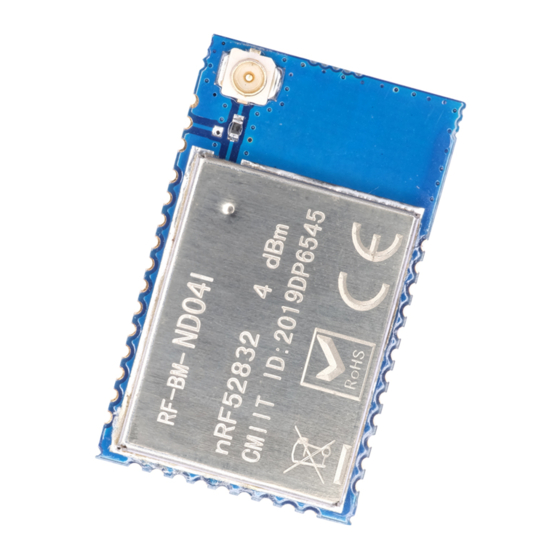
nRF52832 Bluetooth Low Energy 5.0 Master-Slave Module and Protocol
Brand:
RF-Star
| Category:
Wireless modules
| Size: 5 MB
Table of Contents
Table of Contents
3
Table of Tables
6
Table of Figures
6
Summary
7
Overview
8
Introduction
8
Features
8
Supporting Working Mode
9
Default Configuration at Slave Mode
9
Table 1. Power Consumption of Nrf52832
9
Default Configuration at Beacon Mode
10
Device Status
10
Multi-Connection
10
Figure 1. Multi-Connection Diagram
11
Package and Pin Assignment
12
Rf-Bm-Nd04(I)
12
Figure 2. PCB Footprint of RF-BM-ND04
12
Figure 3. PCB Footprint of RF-BM-ND04I
12
Table 2. Pin Functions of RF-BM-ND04(I)
13
Figure 4. Pin Assignment of RF-BM-ND04(I)
13
Rf-Bm-Nd08(I)
15
Figure 5. PCB Footprint of RF-BM-ND08
15
Figure 6. PCB Footprint of RF-BM-ND08I
15
Table 3. Pin Functions of RF-BM-ND08(I)
16
Figure 7. Pin Assignment of RF-BM-ND08(I)
16
UART Transparent Transmission Protocol (Bridge Mode)
18
BLE Protocol Specification (APP Interface)
19
UART Service UUID
19
BLE Data Receiving UUID (RX Characteristic)
19
BLE Data Transmitting UUID (TX Characteristic)
19
AT Command Operation UUID
19
Device Information UUID: 0X180A
20
Manufacturer Name
20
Hardware Revision
20
Firmware Revision
20
System ID
20
Generic Access UUID: 0X1800
21
Device Name
21
Device Appearance
21
Peripheral Preferred Connection Parameters
21
Central Address Resolution
21
AT Command
22
AT Command Format
22
Table 4. at Command Format Table
22
AT Command List
23
Table 5. at Command List
23
Detailed at Command
25
Enter at Command Mode
25
Exit at Command Mode
25
Device Name
25
MAC Address
26
Serial Port Echo
26
Device Status Display
28
Device Role
29
Slave Role Broadcast Parameters
30
Connection Interval
31
Slave Service
32
Master Scan
33
Master Connection
35
Disconnect
36
Automatically Reconnection
37
Designate Role Who Sends Data (Master-Slave at the same Time)
39
Display Current Connected Devices
39
Designate Transmission Device
40
Delete Device
41
Observer
42
Beacon
43
Tx Power
44
Sleep Mode
45
Baud Rate
47
User Authentication
48
Restart Device
49
Reset Device
49
Firmware Version
49
Query the Firmware Version Information and the Date
49
Transparent Transmission Test
50
Test by APP (Android)
50
Test by PC End
53
Preparation before Use
53
Connection Steps
53
Ios APP Programming Reference
59
MCU Reference Code (Transparent Transmission)
62
Application, Implementation and Layout
63
Module Parameters
63
Reference Design
63
Antenna
64
Antenna Design Recommendation
64
Figure 8. Reference Design
64
IPEX Connector
65
Figure 9. Recommendation of Antenna Layout
65
Figure 10. Specification of Antenna Seat
65
Figure 11. Specification of IPEX Wire
65
Antenna Output Mode Modification
66
Basic Operation of Hardware Design
66
Figure 12. Antenna Output Mode Change of RF-BM-ND04I
66
Figure 13. Antenna Output Mode Change of RF-ND08(I)
66
Trouble Shooting
67
Unsatisfactory Transmission Distance
67
Vulnerable Module
68
High Bit Error Rate
68
Electrostatics Discharge Warnings
68
Soldering and Reflow Condition
68
Table 6. Temperature Table of Soldering and Reflow
68
Figure 14. Recommended Reflow for Lead-Free Solder
69
Optional Packaging
70
Figure 15. Optional Packaging Mode
70
Revision History
71
Contact Us
73
Appendix A: Certifications
74
Srrc
74
Fcc
74
Appendix B: Power Consumption Test Screenshot
76
Sleep Mode: 2.76 Μa
76
Broadcast Mode
76
200 Ms Broadcast Cycle: 76.98 Μa
76
500 Ms Broadcast Cycle: 32.79 Μa
77
1000 Ms Broadcast Cycle: 17.53 Μa
77
Connection Mode
78
Ms Connection Interval: 80.35 Μa
78
100 Ms Connection Interval: 27.25 Μa
78
Advertisement
RF-Star RF-BM-ND04I Manual (22 pages)
Bluetooth 5.0 Low Energy Module
Brand:
RF-Star
| Category:
Control Unit
| Size: 1 MB
Table of Contents
Nordic BLE Module List
2
Nrf51 Series
2
Nrf52 Series
3
Device Overview
5
Description
5
Key Features
5
Applications
5
Functional Block Diagram
6
Part Number Conventions
6
Figure 1. Functional Block Diagram of RF-BM-ND04I
6
Figure 2. Part Number Conventions of RF-BM-ND04I
6
Table of Contents
7
Table of Figures
8
Table of Tables
8
Module Configuration and Functions
9
Module Parameters
9
Table 1. Parameters of RF-BM-ND04I
9
Module Pin Diagram
10
Pin Functions
10
Figure 3. Pin Diagram of RF-BM-ND04I
10
Table 2. Pin Functions of RF-BM-ND04I
10
Specifications
12
Recommended Operating Conditions
12
Handling Ratings
12
Power Consumption
12
Table 3. Recommended Operating Conditions of RF-BM-ND04I
12
Table 4. Handling Ratings of RF-BM-ND04I
12
Table 5. Power Consumption
12
Application, Implementation, and Layout
13
Module Photos
13
Recommended PCB Footprint
13
Figure 4. Photos of RF-BM-ND04I
13
Figure 5. Recommended PCB Footprint of RF-BM-ND04I (MM)
13
Schematic Diagram
14
Reference Design
14
Figure 6. Schematic Diagram of RF-BM-ND04I
14
Figure 7. Reference Design of RF-BM-ND04I
14
Antenna
15
Antenna Design Recommendation
15
Figure 8. Recommendation of Antenna Layout
15
IPEX Connector
16
Antenna Output Mode Modification
16
Figure 9. Specification of Antenna Seat
16
Figure 10. Specification of IPEX Wire
16
Basic Operation of Hardware Design
17
Figure 11. Antenna Output Mode Change
17
Trouble Shooting
18
Unsatisfactory Transmission Distance
18
Vulnerable Module
18
High Bit Error Rate
18
Electrostatics Discharge Warnings
18
Soldering and Reflow Condition
19
Table 6. Temperature Table of Soldering and Reflow
19
Optional Packaging
20
Figure 12. Recommended Reflow for Lead-Free Solder
20
Figure 13. Optional Packaging Mode
20
Revision History
21
Contact Us
22
RF-Star RF-BM-ND04I Instruction Manual (29 pages)
Bluetooth 5.0 Low Energy and Bluetooth Mesh Module
Brand:
RF-Star
| Category:
Computer Hardware
| Size: 2 MB
Table of Contents
Device Overview
2
Module Series
2
Description
2
Key Features
2
Applications
3
Functional Block Diagram
3
Part Number Conventions
4
Table of Contents
5
Module Configuration and Functions
7
Module Parameters
7
Module Pin Diagram
8
Pin Functions
8
Specifications
13
Recommended Operating Conditions
13
Handling Ratings
13
Power Consumption
13
Application, Implementation, and Layout
14
Module Photos
14
Recommended PCB Footprint
14
Schematic Diagram
15
Reference Design
16
Antenna
17
Antenna Design Recommendation
17
IPEX Connector
18
Antenna Output Mode Modification
19
External Antenna Design Recommendation of the Half-Hole ANT Pin
19
Basic Operation of Hardware Design
20
Trouble Shooting
21
Unsatisfactory Transmission Distance
21
Vulnerable Module
22
High Bit Error Rate
22
Electrostatics Discharge Warnings
22
Soldering and Reflow Condition
22
Optional Package Specification
24
Certification
26
Fcc
26
Srrc
26
Revision History
28
Contact Us
29
Advertisement
Advertisement
Related Products
RF-Star RF-BM-ND06
RF-Star RF-BM-ND04
RF-Star RF-BM-ND04C
RF-Star RF-BM-ND02
RF-Star RF-BM-ND02C
RF-Star RF-BM-ND07
RF-Star RF-BM-4044B2
RF-Star RF-BM-2340A2I CC2340R5
RF-Star RF-BM-2340B1I CC2340R5
RF-Star RF-BM-2340A2 CC2340R5
RF-Star Categories
Control Unit
Computer Hardware
Wireless modules
Network Hardware
Wireless Router
More RF-Star Manuals
Login
Sign In
OR
Sign in with Facebook
Sign in with Google
Upload manual
Upload from disk
Upload from URL