Sign In
Upload
Manuals
Brands
REXROTH Manuals
DC Drives
Fv Series
REXROTH Fv Series Manuals
Manuals and User Guides for REXROTH Fv Series. We have
3
REXROTH Fv Series manuals available for free PDF download: Instruction Manual, Quick Start Manual
REXROTH Fv Series Instruction Manual (262 pages)
Brand:
REXROTH
| Category:
DC Drives
| Size: 10.91 MB
Table of Contents
Table of Contents
5
1 Introduction
13
Introduction to the Documentation
13
Definition
14
Type Coding
15
Type Coding of Fv
15
Type Coding of Fv Function Modules
16
Engineering Software Type Coding
16
Type Coding of Fv Accessories
16
PROFIBUS Adapter Type Coding
16
Encoder Adapter Type Coding
17
Remote Operation Adapter
17
Interface Adapter Cable Type Coding
17
Operating Panel Cable Type Coding
18
Brake Resistor Type Coding
18
External Brake Chopper Type Coding
19
EMC Filter Type Coding
19
Delivery and Storage
20
Brief Introduction
20
Scope of Supply
20
Transport of the Components
21
Storage of the Components
21
Fv Description
22
Certification
22
CE Certification
22
UL Certification
23
Rcm
24
Properties of the Basic Device Fv
25
Interfaces
25
Cooling Types
25
Version Matching Table
26
2 Safety Instructions for Electric Drives and Controls
27
Definitions of Terms
27
Explanation of Signal Words and the Safety Alert Symbol
28
General Information
28
Using the Safety Instructions and Passing Them on to Others
28
Requirements for Safe Use
29
Hazards by Improper Use
30
Instructions with Regard to Specific Dangers
30
Protection against Contact with Electrical Parts and Housings
30
Protective Extra-Low Voltage as Protection against Electric Shock
31
Protection against Dangerous Movements
32
Protection against Magnetic and Electromagnetic Fields During Operation and Mounting
33
Protection against Contact with Hot Parts
33
Protection During Handling and Mounting
34
3 Important Directions for Use
35
Appropriate Use
35
Inappropriate Use
35
4 Fv Mounting
37
Mounting
37
Fv Dimensions and Figure
39
Fv Dimensions
39
Fv Figure
40
5 Installation
43
Fv Disassembly and Assembly
43
Removal and Mounting of Operating Panel
43
Removal of Operating Panel
43
Mounting of Operating Panel
43
Removal and Mounting of Adapter
44
Removal of Adapter
44
Mounting of Adapter
44
Drive System Wiring
45
Block Diagram
45
Main Circuit Wiring
46
Main Circuit Wiring Cautions
46
Main Circuit Wiring Diagram
47
Main Circuit Wiring Steps
48
Control Circuit Wiring
51
Cable and Fuse Dimensions
51
Introduction
51
Recommendation on Cable Dimensioning
52
Dimensioning Variables of the Table Values
54
Wiring Dimensions for Terminals
55
Wiring Terminals Description
56
Main Circuit Terminals
56
Main Circuit Terminals Description
56
Main Circuit Terminals Illustration
56
Control Circuit Terminals
57
Control Circuit Terminals Description
57
Control Circuit Terminals Illustration
59
Analog Input Terminals (±10 V, VR1, VR2, VR3, GND, +I)
60
Jumper Wiring
60
NPN / PNP Jumper SW1
61
Encoder Signal Selection
62
6 Commissioning
65
Operating Panel
65
Overview
65
3-Level Menu Structure
66
Operation Mode Description
67
Example of Operating Panel Operation
67
Commission Process
68
Check and Preparation before Commissioning
68
Notes on Commissioning
69
Fv Basic Parameter Fast Setting
69
Example: Commissioning of Frequency Converter with Potentiometer
70
Restore Parameters to Factory Defaults
70
Solutions for Simple Fault During Commissioning
71
Notes on Frequent Start and Stop
71
7 Parameter Settings
73
Main Functions
73
Control Command
73
Frequency Setting
74
Start Control
75
Stop Control
76
Linear / S-Curve Acceleration / Deceleration
77
Logic Control
78
PID Control
79
Frequency Setting Via Analog and Pulse Inputs
80
Multiple Function Digital Inputs
81
Analog Outputs
82
Digital Outputs
83
Description of Attribute Symbols in Parameter Tables
84
Parameters Functions
85
Category B: Basic Parameters
85
Group B0: System Parameters
85
Group B1: Basic Parameters
86
Category S: Standard Parameters
88
Group S0: V/F Control
88
Group S1: Vector Control
88
Group S2: Motor and Encoder Parameters
89
Group S3: Control Parameters
90
Category E - Extended Parameters
91
Group E0: Analog and Digital Inputs
91
Group E1: Digital and Analog Outputs
93
Group E2: Multi-Speed and Logic Control
95
Group E3: PID Control
98
Group E4: Protection and Fault Parameters
99
Group E5: Extended Parameters
101
Category H: Advanced Parameters
102
Group H0: Communication Parameters
102
Notes on Function Groups
103
Category B: Basic Parameters
103
Group B0: System Parameters
103
Group B1: Basic Parameters
107
Category S: Standard Parameters
116
Group S0: V/F Control
116
Group S1: Vector Control
120
Group S2: Motor and Encoder Parameters
123
Group S3: Control Parameters
125
Category E: Extended Parameters
130
Group E0: Analog and Digital Inputs
130
Group E1: Analog and Digital Outputs
141
Group E2: Multi-Speed and Logic Control
146
Group E3: PID Control
152
Group E4: Protection Parameters
156
Group E5: Extended Parameters
162
Category H: Advanced Parameters
164
Group H0: Communication Parameters
164
8 Fault Types and Solutions
167
9 Technical Data
171
Electrical Data
171
General Technical Data
172
Derating of Electrical Data
174
Derating and Ambient Temperature
174
Derating and Mains Voltage
175
Derating of the Output Current Depending on the Pulse Frequency
176
Electromagnetic Compatibility (EMC)
177
EMC Requirements
177
General Information
177
Noise Immunity in the Drive System
177
Noise Emission of the Drive System
179
Ensuring the EMC Requirements
182
EMC Measures for Design and Installation
183
Rules for Design of Installations with Drive Controllers in Compliance with EMC
183
EMC-Optimal Installation in Facility and Control Cabinet
185
Control Cabinet Mounting According to Interference Areas - Exemplary Arrangements
186
Design and Installation in Area a - Interference-Free Area of Control Cabinet
187
Design and Installation in Area B - Interference -Susceptible Area of Control Cabinet
189
Design and Installation in Area C - Strongly Interference-Susceptible Area of Control Cabinet
189
Ground Connections
190
Installing Signal Lines and Signal Cables
191
General Measures of Radio Interference Suppression for Relays, Contactors, Switches, Chokes and Inductive Loads
192
10 Accessories
193
EMC Filter
193
The Function of EMC Filter
193
External EMC Filter Type
193
Technical Data
194
Mechanical Data
194
Electrical Data
197
Brake Components
198
Brake Chopper
198
The Function of Brake Chopper
198
Internal Brake Chopper
198
External Brake Chopper (18K5 and above Models)
199
Brake Resistor
203
Brief Introduction
203
Brake Resistor Selection
204
Brake Resistor in Aluminum Housing
207
Brake Resistor Box
209
Encoder Adapter
211
The Function of Encoder Adapter
211
Encoder Adapter Dimensions
211
Encoder Adapter Terminals
212
PROFIBUS Adapter
213
Accessories for Control Cabinet Mounting
213
Remote Operation
213
Operating Panel Cable for Control Cabinet Mounting
214
Engineering Software
214
11 Additional Information
215
Simple Applications of Process Control
215
Automatic Constant Pressure Water Control System
215
Closed-Loop Speed Control System
215
Discharging of Capacitors
216
Discharging of DC Bus Capacitors
216
Discharging Device
216
Operating Principle
216
Dimensioning
216
Installation
217
Activation
217
12 Communication Protocols
219
Introduction
219
Modbus Protocol
219
Protocol Descriptions
219
Transmission
220
Interface
220
Protocol Functions
221
Supported Functions
221
Function Descriptions
222
Communication Mapping Register Address Distribution
227
Introduction
227
Frequency Converter Parameter Registers
227
Communication Control Registers (0X4000, 0X4001, 0X4002)
228
Communication State Feedback Register (0X5000)
229
Communication Monitor Registers (0X5001
230
Modbus Communication Example
231
Special Notes
233
Communication Networking
234
Networking
234
Recommendations on Networking
234
PROFIBUS Protocol
235
Protocol Description
235
PROFIBUS-Adapter
235
Technical Data
235
Functions
235
Network Structure
236
Electrical Installations
236
Outline Structure
236
Adapter Terminal Configuration
236
Requirements for PROFIBUS Link
237
Relationship between Communication Rate and Cables
237
EMC Measures
238
Periodical Data Communication
238
PPO Data Type
238
PKW Parameter Area
239
PZD Process Data Area
243
Addressing of Communications Function Code Parameter Group and Index Number Within the Group
248
Communication Parameter Configuration
249
Communication Related Parameter Settings in Fv
249
Parameter Configuration of Master
249
GSD File
249
Faults and Analysis
250
LED Display Analysis
250
Diagnosis Information of Master
250
13 Service and Support
253
14 Environmental Protection and Disposal
255
Environmental Protection
255
Disposal
255
Index
257
Advertisement
REXROTH Fv Series Instruction Manual (222 pages)
Frequency Converter
Brand:
REXROTH
| Category:
DC Drives
| Size: 10.78 MB
Table of Contents
Table of Contents
5
1 Introduction
11
Introduction to the Documentation
11
Introduction to the Drive System
12
Delivery and Storage
12
Brief Introduction
12
The Scope of Supply Consists of
12
Transport of the Components
12
Storage of the Components
13
Definition
13
Type Coding
14
Type Coding of Fv Series Converters
14
Type Coding of Fv Function Modules
15
Type Coding of Fv Accessories
16
Fv Description
18
Certification
18
CE Certification
18
UL Certification
18
Properties of the Basic Device Fv
18
Interfaces
19
Cooling Types
19
2 Safety Instructions for Electric Drives and Controls
21
General Information
21
Brief Introduction
21
Explanation of Warning Symbols and Degrees of Hazard Seriousness
23
Hazards by Improper Use
23
Instructions with Regard to Specific Dangers
24
Protection against Electric Shock by Protective Low Voltage (PELV)
25
Protection against Dangerous Movements
25
Protection against Magnetic and Electromagnetic Fields During Operation and Mounting
27
Protection against Contact with Hot Parts
27
Protection During Handling and Mounting
28
Protection against Pressurized Systems
28
3 Important Directions for Use
29
Appropriate Use
29
Inappropriate Use
29
4 Frequency Converter Mounting
31
Mounting
31
Fv Dimensions and Outline
32
Fv Dimensions
32
Fv Outline
33
5 Installation
35
Converter Disassembly and Assembly Instruction
35
Removal and Mounting of Operating Panel
35
Removal of Operating Panel
35
Mounting of Operating Panel
35
Removal and Mounting of Adapter
36
Removal of Adapter
36
Mounting of Adapter
36
Drive System Wiring
37
Block Diagram
37
Main Circuit Wiring
38
Main Circuit Wiring Cautions
38
Main Circuit Wiring Diagram
39
Main Circuit Wiring Steps
40
Control Circuit Wiring
41
Cable and Fuse Dimensions
41
Wiring Terminals Description
45
Main Circuit Terminals
45
Control Circuit Terminals
46
Switch Wiring
49
NPN/ PNP Switch SW1
49
NPN and PNP Modes
50
Encoder Signal Selection Switch SW2
51
6 Commissioning
53
Operating Panel
53
Overview
53
3-Level Menu Structure
54
Operation Mode Description
55
Example of Operating Panel Operation
55
Commission Process
55
Check and Preparation before Commissioning
55
Notes on Commissioning
55
Fv Basic Parameter Fast Setting
56
Example: Commissioning of Converter with Potentiometer
56
Restore Parameters to Factory Defaults
57
Solutions for Simple Fault During Commissioning
57
Notes on Frequent Start and Stop
57
7 Parameter Settings
59
Main Functions
59
Control Command
59
Frequency Setting
60
Start Control
61
Stop Control
62
Linear/S-Curve Acceleration/Deceleration
63
Simple PLC Control
64
PID Control
65
Frequency Setting Via Analog Inputs and Pulse Inputs
66
Multiple Function Digital Input Terminals
67
Analog Output Terminals
68
Digital Output Terminals
69
Description of Attribute Symbols in Parameter Tables
70
Parameters Functions
71
Category B: Basic Parameters
71
Group B0: System Parameters
71
Group B1: Basic Parameters
72
Category S: Standard Parameters
74
Group S0: V/F Control
74
Group S1: Vector Control
74
Group S2: Motor and Encoder Parameters
75
Group S3: Run Parameters
76
Category E - Extended Parameters
77
Group E0: Input Terminals
77
Group E1: Output Terminals
79
Group E2: Multi-Speed and Simple PLC
81
Group E3: PID Control
83
Group E4: Protection and Fault Parameters
84
Category H: Advanced Rights
86
Group H0: Communication Parameters
86
Notes on Function Groups
87
Category B: Basic Parameters
87
Group B0: System Parameters
87
Group B1: Basic Parameters
91
Category S: Standard Parameters
99
Group S0: V/F Control
99
Group S1: Vector Control
104
Group S2: Motor and Encoder Parameters
106
Group S3: Run Parameters
108
Category E: Extended Parameters
113
Group E0: Input Terminals
113
Group E1: Output Terminals
122
Group E2: Multi-Speed and Simple PLC Control
127
Group E3: PID Control
132
Group E4: Protection Parameters
135
Category H: Advanced Parameters
139
Group H0: Communication Parameters
139
8 Fault Indication
141
Fault Types and Solutions
141
9 Technical Data
145
Fv General Technical Data
145
Derating of Electrical Data
147
Derating and Ambient Temperature
147
Derating and Mains Voltage
147
Derating of the Output Current Depending on the Pulse Frequency
148
Electrical Parameters
149
Electromagnetic Compatibility (EMC)
150
EMC Requirements
150
General Information
150
Noise Immunity in the Drive System
150
Noise Emission of the Drive System
152
Ensuring the EMC Requirements
155
EMC Measures for Design and Installation
156
Rules for Design of Installations with Drive Controllers in Compliance with EMC
156
EMC-Optimal Installation in Facility and Control Cabinet
157
Ground Connections
161
Installing Signal Lines and Signal Cables
161
General Measures of Radio Interference Suppression for Relays, Contactors, Switches, Chokes and Inductive Loads
162
Selection Matrix for the EMC Accessories
163
10 Accessories
165
EMC Filter
165
The Function of EMC Filter
165
Technical Data
165
Mains Chokes
165
The Function of Mains Chokes
165
Brake Components
165
Brake Unit
165
The Function of Brake Unit
165
Integrated Brake Unit
165
Brake Resistor
166
Brief Introduction
166
Brake Resistor Selection
166
Brake Resistor in Aluminum Housing
169
Brake Resistor Box
172
DV/Dt Filter (Motor Filter)
174
The Function of DV/Dt Filter
174
Technical Data
174
Communication Interface
174
PROFIBUS Adapter
174
Modbus Adapter
174
Accessories for Control Cabinet Mounting
174
Operating Panel for Control Cabinet Mounting
174
Operating Panel Cable for Control Cabinet Mounting
175
Engineering Software
176
11 Additional Information
177
Simple Applications of Process Control
177
Automatic Constant Pressure Water Control System
177
Closed-Loop Speed Control System
177
Discharging of Capacitors
178
Discharging of DC Bus Capacitors
178
Discharging Device
178
Operating Principle
178
Dimensioning
178
Installation
179
Activation
179
12 Communication Protocols
181
Brief Introduction
181
Modbus Protocol
181
Protocol Description
181
Transmission
181
Interface
182
Protocol Functions
182
Supported Functions
182
Function Description
183
Communication Mapping Register Address Distribution
188
Modbus Communication Example
191
Special Notes
191
Communication Networking
192
Networking
192
Recommendations on Networking
192
PROFIBUS Protocol
193
Protocol Description
193
Bosch Rexroth Fieldbus Adapter
193
Technical Data
193
Functions
193
Network Structure
194
Electrical Installations
194
Outline Structure
194
Bus Terminal Resistor
194
Adapter Terminal Configuration
195
Requirements for PROFIBUS Link
195
Relationship between Communication Rate and Cables
196
EMC Measures
196
Periodical Data Communication
197
PPO Data Type
197
PKW Parameter Area
197
PZD Process Data Area
203
Process Data PZD3 - PZD10
206
Examples for Operation of PZD Process Data Area
207
Addressing of Communications Function Code Parameter Group Number and Index Number Within the Group
209
Communication Parameter Configuration
210
Communication Related Parameter Settings in Fv
210
Parameter Configuration of Master
210
GSD File
210
Faults and Analysis
211
LED Display Analysis
211
Diagnosis Information of Master
211
13 Disposal and Environmental Protection
213
Disposal
213
Environmental Protection
213
14 Service and Support
215
Index
217
Introduction
218
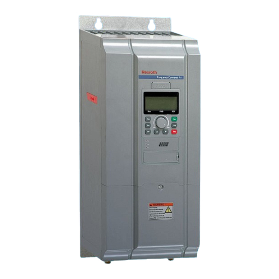
Rexroth Fv Series Quick Start Manual (44 pages)
Frequency Converter
Brand:
Rexroth
| Category:
Media Converter
| Size: 6.83 MB
Table of Contents
Table of Contents
3
1 Mechanical Installation
5
Visual Check
5
Ambient Conditions
5
Installation Conditions
6
Dimensions
7
2 Electric Installation
11
Cable Specifications
11
Power Terminals
16
Interface Connection for Signals
17
3 Parameter Settings
27
Operating Panel
27
Start-Up
27
Operating Descriptions
29
Parameters
30
4 Fault Indication
36
Advertisement
Advertisement
Related Products
REXROTH FVCA Series
Rexroth FECG02.1-1K50
Rexroth FECG02.1-2K20
Rexroth FECG02.1-4K00
Rexroth FECxO2.1-5K50
Rexroth FECxO2.1-18K5
Rexroth FECxO2.1-22K0
Rexroth FECG02.1-0K75
Rexroth FECx02.1-30K0
Rexroth FECxO2.1-55K0
REXROTH Categories
Controller
Engine
DC Drives
Media Converter
Control Unit
More REXROTH Manuals
Login
Sign In
OR
Sign in with Facebook
Sign in with Google
Upload manual
Upload from disk
Upload from URL