Sign In
Upload
Manuals
Brands
Respironics Manuals
Medical Equipment
Millennium H600
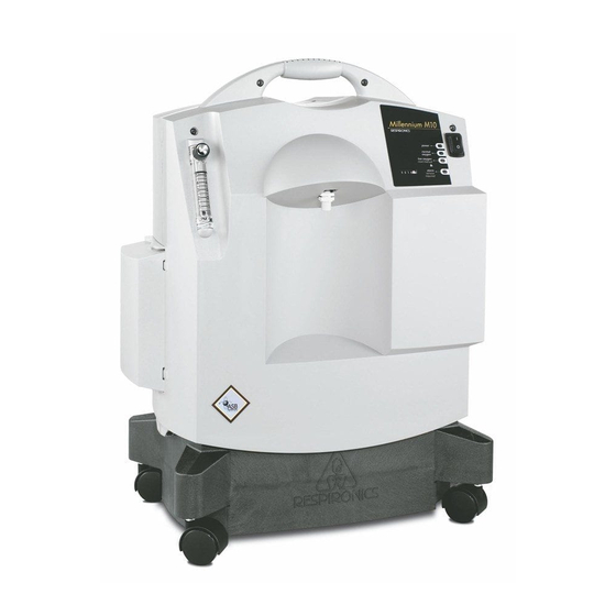
Respironics Millennium H600 Manuals
Manuals and User Guides for Respironics Millennium H600. We have
1
Respironics Millennium H600 manual available for free PDF download: Service And Technical Reference Manual
Respironics Millennium H600 Service And Technical Reference Manual (336 pages)
Respironics Millennium Oxygen Concentrators
Brand:
Respironics
| Category:
Medical Equipment
| Size: 57.35 MB
Table of Contents
Table of Contents
6
Millennium Oxygen Concentrator Overview
12
Types of Concentrations
12
Service Technical
13
Service Notice
13
Service Training
13
Warnings & Cautions
14
Section Overview
14
Cautions
15
Specifications
16
Section Overview
16
H600/605, M600/605, & E
17
Alarm Conditions
18
M10600/M10605 & E
19
Alert Conditions
20
Power Switch
21
Flow Meter
21
Front Cabinet Features
21
Rear and Side Cabinet
21
Control Panel Features
22
System Setup
24
Section Overview
24
Ection Verview
24
H600/605; M600/605; Enhanced M600/605 Testing
26
Theory of Operation
26
Electrical Operation
27
Concentrator Pneumatic Operation
28
M10600/M10605; E
29
Delaer Annual Maintenance
30
Maintenance
30
Maintenance Intervals
30
Weekly User Maintenance
30
Cleaning the Air Inlet Filter
31
Dealer Compressor Maintenance
31
Dealer Periodic Maintenance
31
Cleaning the Pre-Inlet Filter & Inlet Filter
32
Filter Locations
32
Removing the Rear Access Door
32
Cleaning the Cabinet
33
Micro-Disk Filter Maintenance
33
Compressor Maintenance
35
Felt Filter
36
Screw Location
36
Compressor Head Screw Locations
37
O-Ring Location
37
Removing the Valve Plate and Cylinder Sleeve
38
Separating the Cylinder Sleeve and Valve Plate
38
Flapper Valve Removal
39
Installing the Cork Gasket
40
Location of the Piston Cup Retainer Screws
40
Installing the Cylinder Sleeve
41
Installing the Piston Cup & Retainer
41
Cylinder Sleeve in Place
42
Valve Gasket & Alignment Holes
42
Compressor Head in Place
43
Compressor Mounts
46
Corner Markings
46
Screw Locations
47
Valve Plate
47
Cylinder Side of Valve Plate
48
Removing the Cylinder Sleeve
48
Proper Fan Operation
49
Connecting Rod Assembly in Vice
50
Removing the Eccentric
50
Heating the Screw
51
Replace Piston Cup
52
Screw Removal
52
Troubleshooting
56
Corrective Action
57
Concentrator Repair & Replacement
64
Overlay Locations
65
Overlay Replacement
65
To Install the Overlay
65
To Remove the Overlay
65
Caster Replacement
66
To Install the Casters
66
To Remove the Casters
66
Base Cabinet Pan Replacement
67
To Remove the Base Cabinet Pan
67
Location of Blow down Muffler and Foam Cutout
68
To Install the Base Cabinet Pan
68
Rear Cabinet Replacement
69
Rear Cabinet Screw Locations
69
Removing the Rear Cabinet
69
Proper Alignment of Guide Slots and Ridges
70
To Install the Rear Cabinet
70
Flow Meter Replacement
71
Removal of Pressure Tubing from Flow Meter
71
To Remove the Flow Meter
71
Pressure Tubing Connections
72
Removing the Flow Meter
73
To Install the Flow Meter
73
Outlet Fitting Replacement
74
Removing Pressure Tubing from DISS Fitting
74
Removing the Jam Nut
74
To Remove the DISS Outlet Fitting
74
To Install the DISS Outlet Fitting
75
Power Switch Replacement
76
View of Power Switch from Inside the Front Cabinet Assembly
76
Correct Connection of the Wires to the Power Switch
77
Removing the Power Switch from the Front Cabinet Assembly
77
To Install the Power Switch
77
Fuse Location
78
Main PCB Fuse Replacement
78
To Install the Main PCB Fuse
78
To Remove the Main PCB Fuse
78
Connections and Mounting Screw Locations
79
Main PCB Replacement
79
To Remove the Main PCB
79
To Install the Main PCB
80
To Install the OPI Wiring Harness
81
To Remove the OPI Wiring Harness
81
Wiring Harness Replacement
81
OPI Board Replacement
82
To Remove the OPI Board
82
Removing the OPI Board
83
To Install the OPI Board
83
Location of the Connector
84
Main PCB and Power Switch Locations
84
Power Switch Wiring Harness Replacement
84
To Remove the Power Switch Wiring Harness
84
Power Switch Terminal Locations
85
To Install the Power Switch Wiring Harness
85
O2/Solenoid/Battery Wiring Harness
87
Valve/Solenoid Connections
87
Power Switch and Main PCB J1 Location
88
To Install the O2/Solenoid/Battery Wiring Harness
89
Front Cabinet Replacement
90
To Install the Front Cabinet
90
To Remove the Front Cabinet
90
Cooling Fan Replacement
92
Removing Fan from Compressor Housing
92
To Remove the Cooling Fan
92
Wire and Screw Locations
92
To Install the Cooling Fan
93
Perforate Canopy Replacement
94
To Install the Perforated Canopy
94
To Remove the Perforated Canopy
94
Compressor Cover Replacement
95
To Install the Compressor Cover
95
To Remove the Compressor Cover
95
Location of the Main Power Wiring Harness
96
Main Power Wiring Harness Replacement
96
To Remove the Main Power Wiring Harness
96
Main Power Wiring Harness Connected to the Power Switch Wiring Harness
97
To Install the Main Power Wiring Harness
98
Capacitor Location
99
Motor Start/Run Capacitor
99
To Install the Motor Start/Run Capacitor
99
To Remove the Motor Start/Run Capacitor
99
Pressure Relief Valve Replacement
100
To Install the Pressure Relief Valve
100
To Remove the Pressure Relief Valve
100
Compressor Assembly Replacement
101
To Remove the Compressor Assembly
101
Location of the Shoulder Screws and Rubber Bumpers
102
Removing the Compressor Assembly
102
To Install the Compressor Assembly
103
In-Line Muffler Replacement
104
Location of the One-Eared Clamps
104
To Remove the In-Line Muffler
104
Correct Orientation of the In-Line Muffler
105
To Install the In-Line Muffler
105
Hour Meter Replacement
106
Removing the Hour Meter Wires
106
To Remove the Hour Meter
106
To Install the Hour Meter
107
Location of the Screws Securing the Valve/Solenoid Assembly
108
To Remove the Valve/Solenoid
108
Valve/Solenoid Replacement
108
Removing the Valve/Solenoid Assembly
109
To Install the Valve/Solenoid Assembly
109
Pressure Regulator Replacement
110
To Install the Pressure Regulator
110
To Remove the Pressure Regulator
110
Sieve Canister Assembly Replacement
111
To Install the Sieve Canister Assembly
112
Blow down Muffler Replacement
113
To Remove the Blow down Muffler
113
Assembly
114
To Install the Blow down Muffler
114
Power Cord Replacement
115
To Remove the Power Cord
115
To Install the Power Cord
116
Base Cabinet Replacement
117
To Install the Base Cabinet
117
To Remove the Base Cabinet
117
Eplacement
118
Overview
118
Repair
118
OPI Wiring Harness Replacement
131
Eplacement
164
Eplacement
181
Wiring
186
Replacement
188
Replacement
208
Eplacement
209
Eplacement
211
Replacement
211
Eplacement
212
Eplacement
214
Replacement
216
Wiring
218
Replacement
226
Main PCB to Cooling Fan Wiring Replacement
230
To Install the Main PCB to Cooling Fan Wiring
230
To Remove the Main PCB to Cooling Fan Wiring
230
Locking Post Location
231
Perforated Canopy Replacement
231
Thermal Protection Switch Replacement
240
To Install the Thermal Protection Switch
240
To Remove the Thermal Protection Switch
240
Eplacement
241
Table
257
Ac Inlet Kit
260
Alarm Battery Kit
260
Power Cord Retainer Kit
260
230V AC Inlet Fuse Kit
261
230V Fuse Holder Kit
261
Base Cabinet Kits
262
Base Pan Kit
263
Blow down Muffler Kits
263
Blower Assembly Replacement
264
Cabinet Hardweare Kit
264
Cable Tie Kit
264
Capacitor Kits
265
Caster Kits
266
Compressor Kits
267
Compressor Elbow Fitting Kit
268
Compressor Inlet Adaptor Kit
268
Compressor Maintenance Kits
268
Spare Gasket & Seal Kit
269
Spare Piston Cup Seal Kit
269
Spare Plate, Valve, Flapper Kit
269
Compressor Mounting Kits
272
Compressor Spring Kit
273
Cooling Fan Kits
275
DISS Outlet Fitting Kit
275
Elbow/Hose Kit
275
Air Inlet Filter Kits
276
Long Life Filter Kits
276
Long Life Filter Retrofit Kit
276
Inlet Filter Kits
277
Silicone Grommet Kit
277
Whisper Cap Kits
277
Inlet Filter W/Silencer Kits
278
Silencer Kits
278
Micro-Disk Filter Kit
279
Pre-Inlet Filter Kits
279
Retainer Inlet Filter Kits
279
Felt Filter Kit
280
Filter Cover Kit
280
Retainer Air Intake Kit
280
Flow Meter Kits
281
Flow Meter Knob Kit
282
Stand Alone Pediatric Flow Meter Kit
282
Foam Kit
283
Front Cabinet Kits
284
Gasket Kits
285
Main PCA Fuse Kits
285
Hour Meter Kits
286
In-Line Muffler Kits
287
OPI PCB Kit
288
Overlay Kits
289
Warning/Instructions Label Kits
291
Perforated Canopy Kit
292
Power Switch Kits
292
Pressure Regulator Kit
293
Pressure Relief Valve Kit
293
Main PCA Kits
294
Power Cord Kit
295
Rear Access Door Kits
295
Rear Cabinet Kits
296
One-Eared Clamp Kit
297
Serial Number Plate Kits
297
Shipping Carton Kits
298
Sieve Canister Kits
298
Shipping Carton Insert Kits
299
Tubing Kit
299
Valve/Solenoid Kits
300
Main Power Wiring Harness Kits
301
Solenoid Gasket Kit
301
O2/Solenoid/Battery Wiring Harness Kit
302
Main PCB to Fan Cable Wiring Kit
303
Power Switch Wiring Harness Kit
303
Thermal Protection Switch Kit
303
Main PCB to Battery Cable Wiring Kit
304
Main Pcb to Compressor Cable Wiring Kit
304
Battery Test & Replacement
306
Enhanced Testing
306
System Pressure Test
306
System Verification Procedures
306
Oxygen Outlet/Regulated Pressure Test
307
OPI PCB Oxygen Verification
309
Opi Voltage Verification Chart
310
Millennium System Final Test
311
Pin Locations
312
Model 605 Test Data Sheet
313
Sheet
316
M10600/M10605 & Enhanced M10600/M10605 Testing System Verification Procedures
318
System Verification Procedures
318
Millennium System Final Test
322
M10605 Test
324
Sheet
324
M10600 Test
325
Sheet
325
Service Tools & Supplies
326
Tools & Test Equipment
326
Acceptable Test Equipment
327
Schematics Statement
328
Advertisement
Advertisement
Related Products
Respironics Millennium H605
Respironics HomeLOX
Respironics System One Heated Humidifier
Respironics Millennium
Respironics Millennium M10600
Respironics Millennium M10605
Respironics Millennium Enhanced M600
Respironics Millennium Enhanced M605
Respironics Millennium M10
Respironics 1002720
Respironics Categories
Medical Equipment
Respiratory Product
Humidifier
Fan
Oxygen Equipment
More Respironics Manuals
Login
Sign In
OR
Sign in with Facebook
Sign in with Google
Upload manual
Upload from disk
Upload from URL