Sign In
Upload
Manuals
Brands
RenewAire Manuals
Fan
DN3RT
RenewAire DN3RT Manuals
Manuals and User Guides for RenewAire DN3RT. We have
3
RenewAire DN3RT manuals available for free PDF download: Installation, Operation And Maintenance Manual, Supplemental Manual, Instruction Manual
RenewAire DN3RT Installation, Operation And Maintenance Manual (72 pages)
Brand:
RenewAire
| Category:
Fan
| Size: 6 MB
Table of Contents
Table of Contents
21
1 Overview
26
Description
26
Energy Recovery
26
Ventilation Air
26
Heating
26
Cooling
26
Reheat
26
Model Sizes
27
Figure 1.2.0 DN DOAS Modules
27
Figure 1.2.1 DN DOAS with Alternate SA Fan Position
27
Airflows
28
Airflow Inlet and Outlet Configurations
28
Figure 1.3.0 Airflow Configuration for Orientation H
28
Figure 1.3.1 Airflow Configuration for Orientation R
28
Internal Airflow
29
Figure 1.3.2 Airflow Configuration for Orientation F
29
Figure 1.3.3 Airflow Configuration for Orientation V
29
Figure 1.3.4 Plan View of Airflow During Energy Recovery Mode
29
Figure 1.3.5 Plan View of Airflow During Bypass Mode
30
Figure 1.3.6 Plan View of Airflow During Recirculation Mode
30
Heating
31
Gas Heat Module
31
Electric Heat Module
31
Water Coil/Steam Coil
31
Figure 1.4.0 Gas Heat Module (Typical)
31
Figure 1.4.1 Electric Heat Module (Typical)
31
Figure 1.4.2 Water Coil (Typical)
31
Cooling
32
Split DX Coil
32
Chilled Water Coil
32
Hot Gas Reheat
32
Figure 1.5.0 DX Coil (Typical)
32
Figure 1.5.1 Hot Gas Reheat Coil
32
2 Component Description
33
Cabinet Construction
33
Cabinet Paint
33
Fan Motors
33
Fan Speed Control
33
Figure 2.2.0 EC Fan Assembly (Standard)
33
Figure 2.2.1 Asynchronous Motor Fan Assembly (Optional)
33
Dampers
34
Figure 2.3.0 EA Fan with Damper (Behind)
34
Figure 2.3.1 OA Damper and Actuator
34
Figure 2.3.2 Face and Bypass Dampers
34
Enthalpic Cores
35
Filters
35
Filter Monitors
35
Controls
35
Integrated Programmable Controls
35
Variable Frequency Drive (Optional)
35
Figure 2.3.3 Bypass Assy Viewed from Front
35
Figure 2.3.4 Recirculation Damper Inside Bypass Assembly
35
Gas Heat Module (Optional)
36
Electric Heat Module (Optional)
36
Split DX Cooling (Optional)
36
Figure 2.6.0 Integrated Controls Installed
36
Hot Gas Reheat (Optional)
37
Chilled Water Cooling (Optional)
37
Optional Overflow Switch
37
Waterless Drain Traps
37
Figure 2.11.0 Optional Overflow Switch
37
Hot Water/Steam Heating (Optional)
38
3 Shipping/Receiving/Handling
38
Unit Weights/Dimensions
38
Unit Dimensions and Weight
38
Shipping Dimensions and Weight
39
Dn-2-Rt Corner Weights
39
Figure 3.1.0 DN-2-RT Approximate Corner Weights
39
Dn-3-Rt Corner Weights
40
Dn-5-Rt Corner Weights
40
Figure 3.1.1 DN-3-RT Approximate Corner Weights
40
Figure 3.1.2 DN-5-RT Approximate Corner Weights
40
Receiving
41
Rigging
41
Handling and Storage
41
4 Unit Placement
41
Sound Attenuation Outside the Building
41
Placement Cautions
41
Service Clearances
41
5 Installation
42
Curb Assembly/Equipment Rail Placement
42
Unit Placement
42
Hood Installation
43
Duct Connections
43
Indoor Sound Attenuation
43
Electrical Requirements
44
Factory-Recommended Electric Service Entry
44
Figure 5.5.0 Factory-Recommended Electric Service Entry
44
High-Voltage Electrical Connections
45
Low Voltage Electrical Connections
45
Figure 5.5.1 Disconnect Switch (Typical)
45
Figure 5.5.2 Low Voltage Terminal Blocks Installed
45
Figure 5.5.3 Field Wiring
46
VAC Class II Power Supply
47
Figure 5.5.4 24 VAC Power Supply Transformer
47
Wiring Schematics
48
Typical Input Power
48
Figure 5.6.0 DN-2 Single Phase Power Wiring Schematic
48
Figure 5.6.1 DN-2, DN-3 Three Phase Power Wiring Schematic
49
Figure 5.6.2 DN-5 Three Phase Power Wiring Schematic
50
Typical Control Wiring
51
Figure 5.6.3 DN-2, DN-3, DN-5 Typical Control Wiring
51
Typical Field Wiring
52
Figure 5.6.4 DN-2, DN-3, DN-5 Typical Field Wiring
52
Piping Connections
53
Coil Connections
53
Figure 5.7.0 Suction Line for DX Coil
53
Figure 5.7.1 Cabinet Floor Piping Penetrations
54
Drain Traps
55
Figure 5.7.2 Condensate Drain Location (Typical)
55
Figure 5.7.3 SA Fan Module Located before the Coil Module
56
Figure 5.7.4 SA Fan Module Located after the Coil Module
56
Figure 5.7.5 Condensate Drain Trap Clearances
56
Drain Trap Construction
57
Figure 5.7.6 Typical Drain Trap Construction
57
Figure 5.7.7 Positive Pressure Drain Trap Consruction
57
Waterless Drain Traps
58
Figure 5.7.8 Negative Pressure Drain Trap Construction
58
Gas Requirements
59
Figure 5.7.9 Type "P" Positive Pressure Waterless Trap
59
Figure 5.7.10 Type "N" Negative Pressure Waterless Trap
59
6 Operation
60
Principle of Operation
60
Pre Start-Up
60
Verify Voltage
60
Verify Transformer Wiring
60
Inspect Filters
60
Inspect Fans
60
Inspect and Clean the Interior
60
Inspect Ductwork Connections
60
Basic Operational Check
60
Current Switches
61
Final Unit Set-Up
61
7 Maintenance
61
Schedule
61
General Cleaning and Inspection (Quarterly)
61
Filters (Quarterly)
61
Filter Pressure Drop Tables
62
Cabinet Maintenance (Annual)
62
Electric Motor Maintenance (Annual)
62
Vfds (Optional)
63
Enthalpic Core Maintenance (Annual)
63
OA Hood Maintenance (Annual)
64
Figure 7.1.0 End View of Core Support Assembly
64
Figure 7.1.1 OA Hood Access
64
Coil Maintenance (Annual)
65
Condensate Drain Maintenance (Annual)
65
Damper Maintenance (Annual)
66
Fan Maintenance (Annual)
66
Gas Heat Module Maintenance (Annual)
66
Electric Heat Module Maintenance (Annual)
66
Current Switch Adjustment
66
Figure 7.1.2 Current Switch (Typical)
66
Door Latch Adjustment
67
Fan/Motor Removal
67
Figure 7.1.3 Door Latch Adjustment
67
Figure 7.1.4 Single Phase EC Motor Wiring Connections
67
Figure 7.1.5 Three Phase EC Motor Wiring Connections
67
Coil Removal
68
Water Treatment
68
Winterization
68
Figure 7.1.6 Asynchronous Motor and Fan Assembly Correct
68
Maintenance Records
69
Service Parts
70
Figure 7.3.0 DN Service Parts
70
8 Troubleshooting
71
9 Factory Assistance
71
Advertisement
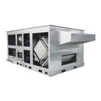
RenewAire DN3RT Supplemental Manual (60 pages)
Brand:
RenewAire
| Category:
Refrigerator
| Size: 4 MB
Table of Contents
Table of Contents
6
1 Overview
8
Description
8
System Sizing
8
Cooling Capacity
8
Reheat Capacity
9
Evaporator Coil Operation
9
Condensing Coil Operation
9
Hot Gas Reheat Coil Operation
9
User Interface
10
Safety Features
10
Figure 1.8.0 Programmable Controller as Used for DOAS and Packaged Refrigeration Control
10
2 Component Descriptions
11
Cabinet
11
Figure 2.1.0 DOAS with Packaged Refrigeration: Front View
11
Figure 2.1.1 DOAS with Packaged Refrigeration: Back View
11
Figure 2.1.2 DOAS with Packaged Refrigeration: EA Fan Compartment
11
Refrigerant
12
Polyolester Oil
12
Evaporator Coil
12
Condensing Coil
12
Figure 2.5.0 DOAS Condensing Coil Location
12
Condenser Fans
13
Compressors
13
Figure 2.6.0 DOAS Condenser Fan (Shroud Not Shown)
13
Figure 2.7.0 Variable-Speed and Fixed-Speed
13
Figure 2.7.1 Compressor Usage
13
Compressor Crankcase Heaters
14
Variable Frequency Drive (VFD)
14
Controller
14
Figure 2.7.2 External Crankcase Heater (Typ)
14
Figure 2.7.3 VFD and Fuse Block
14
Electronic Expansion Valve (Eev)
15
Filter-Drier
15
Figure 2.8.0 DOAS Controller and Refrigeration Controller
15
Figure 2.9.0 Electronic Expansion Valve (EEV)
15
Figure 2.10.0 Filter-Drier
15
Sight Glass
16
Pressure Limit Switch
16
Temperature Sensor and Pressure Transducer
16
Figure 2.11.0 Sight Glass
16
Figure 2.12.0 Pressure Limit Switch
16
Figure 2.13.0 Temperature Sensor and Pressure Transducer
16
Service Port
17
Hot Gas Reheat Coil (Option)
17
Suction Accumulator (Option)
17
Figure 2.14.0 Service Port (Typ)
17
Figure 2.15.0 HGRH Coil
17
Figure 2.16.0 Suction Accumulator
17
Modulating 3-Way Valve (Option)
18
Check Valve (Option)
18
Figure 2.17.0 Modulating 3-Way Valve
18
Figure 2.18.0 Check Valve
18
3 Shipping/Receiving/Handling
19
Unit Weights and Dimensions
19
Unit Dimensions and Weight
19
Shipping Dimensions and Weight
19
DN-2-RT Packaged Corner Weights and COG Drawing
20
DN-3-RT Packaged Corner Weights and COG Drawing
21
DN-5-RT Packaged Corner Weights and COG Drawing
22
4 Unit Placement
23
5 Installation
23
Electrical Connections
23
High-Voltage Power Supply
23
Low-Voltage Power Supply
23
Condensing Unit Wiring Schematic
24
Single-Circuit Wiring Schematic
24
Figure 5.2.0 High Voltage Single-Circuit Wiring Schematic (Typ)
24
Figure 5.2.1 Control Single-Circuit Wiring Schematic (Typ)
25
Two-Circuit Wiring Schematic
26
Figure 5.2.2 High Voltage Two-Circuit Wiring Schematic (Typ)
26
Figure 5.2.3 Control Two-Circuit Wiring Schematic (Typ)
27
P&I Diagrams (Process and Instrumentation)
28
Figure 5.3.0 Variable Speed Circuit, no HGRH
28
Figure 5.3.1 Variable Speed Circuit, with HGRH
28
Figure 5.3.2 Fixed Speed Circuit
28
Refrigerant Pressure Charts
29
Figure 5.4.0 R-410A Saturation Properties
29
Refrigerant Charge Charts
30
Check and Charge Refrigerant
30
Figure 5.5.0 Oil Charge by Compressor Model
30
6 Unit Operation
31
Principle of Operation
31
Enable the Unit Locally
31
Figure 6.1.0 Enabling the Unit Locally
31
Checking for Critical Alarms
32
Enable Signal from Main Controller
32
Viewing the Current State of the Unit
32
Controlling the Unit
32
Figure 6.1.1 Main Unit Status Screen
32
Figure 6.2.0 Main Unit Status Screen
32
Demand Calculation
33
Figure 6.2.1 Variable Speed Compressor States
33
Figure 6.2.2 Unit Status Timer Screen
33
Unit Running States-Single Compressor
33
Figure 6.2.3 General Compressor Settings
34
Figure 6.2.4 Compressor Safety Timing Settings
34
Safety Timing
34
Additional State for Second Compressor
35
Figure 6.2.5 Staging of Second Compressor
35
Figure 6.2.6 Second Compressor Staging Parameters
35
Figure 6.2.7 Second Compressor Staging Diagram
35
Relative Values to Illustrate Compressor Staging Concept
35
Example to Illustrate Compressor Staging Concept
36
Figure 6.2.8 Compressor Staging Example-Increasing Demand
37
Figure 6.2.9 Compressor Staging Example-Decreasing Demand
37
Compressor Envelope Control
38
Compressor Oil Management
38
Figure 6.2.10 Oil Management Parameters
38
Figure 6.2.11 Envelope Alarm Timing Parameter
38
Figure 6.2.12 Main Unit Status Screen-Shows
38
Figure 6.2.13 Envelope Zones Defined
38
Condenser Fan Control
39
Superheat Control
39
Crankcase Heater
39
7 Start-Up
39
Figure 6.2.14 Superheat Setpoint
39
Figure 6.2.15 Electronic Expansion Valve Status Screen
39
Figure 6.2.16 Electronic Expansion Valve Status Screen
39
Figure 6.2.17 Condenser Fan Parameters
39
8 Maintenance
40
Maintenance Schedule
40
Service Requirements
40
Commissioning Maintenance
41
Start-Of-Cooling Season Maintenance (Annual)
41
End-Of-Cooling Season Maintenance (Annual)
42
Periodic Maintenance (Monthly)
42
Figure 8.1.0 Swing-Down Condenser Screen
42
Maintenance Records
43
Commissioning Maintenance Log
43
Start-Of-Cooling Season Maintenance Log
44
End-Of-Cooling Season Maintenance Log
46
Periodic Maintenance (Monthly)
48
Service Notes
49
Service Parts
50
9 Troubleshooting
50
Alarms
50
Figure 8.3.0 Packaged DN Service Parts
50
Figure 9.1.0 Device Management Alarms
50
Figure 9.1.1 Refrigerant Probe Alarms
51
Figure 9.1.2 General Maintenance Alarms
51
Figure 9.1.3 Refrigerant Circuit 1 Alarms
52
Figure 9.1.4 Refrigerant Circuit 2 Alarms
53
Figure 9.1.5 Siam Compressor Alarms
54
Figure 9.1.6 Siam Compressor Alarms Continued
55
Sequence of Operation
56
Figure 9.1.7 Siam Compressor Alarms Continued
56
Bms Integration
57
Figure 9.3.0 BMS Points
57
10 Factory Assistance
58
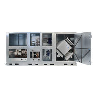
RenewAire DN3RT Instruction Manual (36 pages)
Dedicated Outdoor Air System
Brand:
RenewAire
| Category:
Air Handlers
| Size: 4 MB
Table of Contents
Table of Contents
4
Overview
6
Shipping/Receiving/Handling
7
Off-Loading
7
Forklift Use
7
Hoisting
8
Figure 2.3.0 Example of Minimum Hoisting Requirements
9
Dn2In Drawings
10
DN2IN Dimensioned Drawing
10
DN2IN Center of Gravity Drawing
11
Dn2Rt Drawings
12
DN2RT Dimensioned Drawing
12
DN2RT Center of Gravity Drawing
13
DN2RT with Packaged Refrigeration Dimensioned Drawing
14
DN2RT with Packaged Refrigeration Center of Gravity Drawing
15
DN2RT Full-Sized Curb Drawing
16
DN2RT Curb Mounting Drawing
16
Dn3In Drawings
17
DN3IN Dimensioned Drawing
17
DN3IN Center of Gravity Drawing
18
Dn3Rt Drawings
19
DN3RT Dimensioned Drawing
19
DN3RT Center of Gravity Drawing
20
DN3RT with Packaged Refrigeration Dimensioned Drawing
21
DN3RT with Packaged Refrigeration Center of Gravity Drawing
22
DN3RT Full-Size Curb Drawing
23
DN3RT Curb Mounting Drawing
23
Dn5In Drawings
24
DN5IN Dimensioned Drawing
24
DN5IN Center of Gravity Drawing
25
Dn5Rt Drawings
26
DN5RT Dimensioned Drawing
26
DN5RT Center of Gravity Drawing
27
DN5RT with Packaged Refrigeration Dimensioned Drawing
28
DN5RT with Packaged Refrigeration Center of Gravity Drawing
29
DN5RT Full-Size Curb Drawing
30
DN5RT Curb Mounting Drawing
30
Installation Preparation
32
Drain Trap Preparation
32
Unit Storage
32
Rooftop Curbs
32
Curb Clips
32
Figure 3.4.0 Curb Clips Typical Installation
32
Equipment Rails
33
Pre-Position Ductwork
33
Lateral Ground Movement
33
Unit Placement
33
Installation of Hoods
34
Outside Air Hood
34
Exhaust Air Hood
34
Utility and Mechanical Connections
34
Figure 3.9.0 Outside Air Hood (Typical)
34
Figure 3.9.1 Exhaust Air Hood (Typical)
34
Figure 3.10.0 Piping Penetrations Drawing a
35
Figure 3.10.1 Piping Penetrations Drawing B
35
Advertisement
Advertisement
Related Products
RenewAire DN-Series
RenewAire DN-2
RenewAire DN-3
RenewAire DN-5
RenewAire DN-2-JIN
RenewAire DN2RT
RenewAire DN5RT
RenewAire DOAS DN Series
RenewAire DN2IN
RenewAire DN3IN
RenewAire Categories
Fan
Air Conditioner
Heating System
Controller
Industrial Equipment
More RenewAire Manuals
Login
Sign In
OR
Sign in with Facebook
Sign in with Google
Upload manual
Upload from disk
Upload from URL