Sign In
Upload
Manuals
Brands
Renesas Manuals
Motherboard
ZSSC3240KIT
Renesas ZSSC3240KIT Manuals
Manuals and User Guides for Renesas ZSSC3240KIT. We have
1
Renesas ZSSC3240KIT manual available for free PDF download: User Manual
Renesas ZSSC3240KIT User Manual (54 pages)
Evaluation Kit
Brand:
Renesas
| Category:
Motherboard
| Size: 3 MB
Table of Contents
Table of Contents
2
Evaluation Kit Setup
6
Required or Recommended User Equipment
6
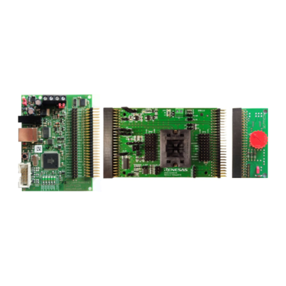
Figure 1. Connected Boards
6
User Computer Requirements and Setup
7
Computer Requirements
7
Software Installation and Setup
7
Boards Configuration and Connections
7
Figure 2. Zssc324X SSC Evaluation Board - Overview
8
Table 1. Sensor Signal at Connectors
8
Figure 3. Signal Connections: SSC Communication Board and Zssc324X EVB
9
Table 2. Leds
9
Table 3. Signal Connections: SSC Communication Board and Zssc324X Evaluation Board
9
Figure 4. Signal Connections: Zssc324X EVB and SRB
10
Table 4. Signal Connections: Zssc324X Evaluation Board and the Sensor Replacement Board
10
Table 5. Evaluation Board Connections Descriptions
11
Kit Hardware Connections (Default)
12
Table 6. Jumper Settings for Analog Output Selection
12
Table 7 Jumper Settings for Digital Interface Selection
12
Communication Interfaces
13
External Equipment Connections
13
Figure 5. Jumpers on the SSC Communication Board and the Zssc324X EVB
13
Power Supply Option
14
Figure 6. Lab Equipment Connections
14
Power-Up Procedure
15
Figure 7. Leds Status CB - Ready for Operation (Without GUI Running)
15
Table 8. Power Supply Selection
15
Figure 8. LED Status after Starting the Evaluation SW
16
Figure 9. Initial GUI Display
16
Gui
17
Menu Bar
17
NVM Control
17
Figure 10. Zssc324X GUI Main Screen
17
Interface Setup
18
Figure 11. Nvm_Config Text File
18
Figure 12. Communication Interface Setup SPI
19
Figure 13. Communication Interface Setup - I2C
19
Figure 14. Communication Interface Setup - OWI
19
Output Interrupt Signaling
20
Current Interface Settings
20
Figure 15. Threshold Setup
20
Measurement Control
21
Measurement Commands
21
Figure 16. Corrected Measurement Oversampling
21
Figure 17. Cyclic Measurements - Busy Status
22
Table 9. Measurement Commands
22
Display Control
23
Figure 18. Measurements Visualization
23
Logging Options
24
Communication Log
24
Figure 19. Resolution Range from Chip to GUI
24
Figure 20. Logging Options
24
Figure 21. Communication Log SPI
24
Figure 22. Communication Log I2C
24
Measurement Data Log
25
Status
25
IC Status
25
Figure 23. Communication OWI
25
Figure 24. IC Status
25
Hardware Connection
26
Table 10. IC Status Indicators
26
Sensor and Temperature Readings
27
Tabs
27
Measurement Tab
27
NVM Tab
27
Figure 25. HW Connection
27
Figure 26. Sensor and Temperature Display
27
Figure 27. NVM Table
28
Figure 28. SM Config 1/2 Sub-Tab
29
Figure 29. Ext Temp. 1/2 Sub-Tab
29
Calibration Tab
30
Figure 30. Smart Sensor Function I/O 1 Sub-Tab
30
Figure 31. Smart Sensor Function I/O 2 Sub-Tab
30
Figure 32. Calibration Tab
31
Figure 33. Raw Data to Calibrated Data in Percentage
31
Diagnostic / Cyclic Configuration / Command Section
32
Table 11. Supported Default Calibration Types
32
Figure 34. Diagnostic / Cyclic Configuration /Command Section
33
Figure 35. Cyclic Operation Parameters
33
Figure 36. ADC and DAC Diagnostics
34
Figure 37. Sensor Check Selection Settings
35
Main Buttons
36
Figure 38. Single Commands Options
36
Figure 39. Read/Write Operations Via Terminal
36
Information Bar
37
Figure 40. Main Buttons
37
Figure 41. Information Bar Message
37
Calibration Process, Configuration and Calibration Example
38
Process Flowchart
38
Figure 42. Calibration Process Flowchart
38
Connect EVK and Start GUI
39
Configuration
39
Figure 43. NVM Coefficients before Calibration
39
Figure 44. AFE Settings
40
Figure 45. Display and Control Settings
40
Figure 46. Output Swing
40
Data Collection
41
Figure 47. Saturation Condition
41
Figure 48. Calibration Points Set Options
41
Figure 49. 2-Points Calibration - Reference Points
41
Figure 50. 2-Points Calibration - Points Position
42
Figure 51. 2-Points Calibration - First Point
42
Coefficients Calculation
43
Figure 52. 2 Points Calibration - Raw Values
43
Figure 53. Calculated Coefficients
43
Figure 54. Calculation Error Message
43
Memory Programming
44
Figure 55. NVM View with New Register Values after Calibration
44
Verification
45
Figure 56. Calibrated Sensor Measurement
45
Board Supply by External JFET
46
Figure 57. External Supply Connections
46
Figure 58. External Supply GUI Settings
46
Analog Output
47
Enabling Analog Output Pin
47
Figure 59. Measurement Control for Analog Output
47
Figure 60. Analog and Digital Output Synchronous Swing
47
Amplified Analog Output
48
Current Loop Output
48
Table 12. Jumper Settings for Amplified Analog Output
48
Troubleshooting
49
GUI Launched While the Communication Board Is Not Connected
49
Figure 61. Connection Error Message
49
Figure 62. Resume Communication
49
Unplugging Communication Board with Port Open
50
Schematic, Bill of Materials
50
Figure 63. Close Port before Unplugging the Communication Board
50
Glossary
51
Table 13. Abbreviations and Terms Used in the Document
51
Ordering Information
52
Revision History
52
Advertisement
Advertisement
Related Products
Renesas ZSSC3170
Renesas ZSSC324 Series
Renesas ZSSC3241EVB
Renesas ZSSC5101
Renesas ZL2102DEMO1Z
Renesas ZMOD4410
Renesas ZL2005PEVK4
Renesas ZL2005P
Renesas ZL9006MEVAL1Z
Renesas ZL9010MEVAL1Z
Renesas Categories
Computer Hardware
Motherboard
Microcontrollers
Adapter
Switch
More Renesas Manuals
Login
Sign In
OR
Sign in with Facebook
Sign in with Google
Upload manual
Upload from disk
Upload from URL