Sign In
Upload
Manuals
Brands
Renesas Manuals
Computer Hardware
RX261 Series
Renesas RX261 Series Manuals
Manuals and User Guides for Renesas RX261 Series. We have
2
Renesas RX261 Series manuals available for free PDF download: User Manual
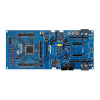
Renesas RX261 Series User Manual (57 pages)
Evaluation Kit for Microcontroller
Brand:
Renesas
| Category:
Motherboard
| Size: 2 MB
Table of Contents
Corporate Headquarters
2
Contact Information
2
Proprietary Notice
4
Table of Contents
5
List of Abbreviations and Acronyms
9
Table 1. List of Abbreviations and Acronyms
9
Kit Overview
10
Figure 1. EK-RX261 V1 Top Side
11
Figure 2. EK-RX261 V1 Bottom Side
12
Assumptions and Advisory Notes
13
Kit Contents
14
Ordering Information
14
Figure 3. EK-RX261 V1 Kit Contents
14
Hardware Architecture and Default Configuration
15
Kit Architecture
15
Table 2. Kit Architecture
15
Figure 4. EK-RX261 V1 Area Definitions
16
System Block Diagram
17
Figure 5. EK-RX261 V1 Block Diagram
17
Component Placement Location and Dimension
18
Figure 6. Reference Number for Components on the EK-RX261 V1 (Top Side)
18
Figure 7. Reference Number for Components on the EK-RX261 V1 (Bottom Side)
19
Figure 8. Dimension of the EK-RX261 V1
20
Jumper Settings
21
Copper Jumpers
21
Traditional Pin Header Jumpers
21
Default Jumper Configuration
21
Figure 9. Copper Jumpers
21
Table 3. Default Jumper Settings
22
System Control and Ecosystem Access Area
24
Power
24
Figure 10. System Control and Ecosystem Access Area
24
Usb Debug1
25
Usb Full Speed
25
Usb Serial
25
External DC Power Supply
25
Power Supply Considerations
25
Power-Up Behavior
25
Figure 11. Power Supply
25
Debug
26
Table 4. Debug Modes
26
Table 5. Jumper Connection Summary for Different Debug Modes
26
Figure 12. EK-RX261 V1 Debug Interface
27
Debug On-Board
28
Table 6. USB DEBUG1 Connector
28
Table 7. Debug On-Board Jumper Configuration
28
Debug in
29
Table 8. Debug in Mode Jumper Configuration
29
Table 9. 14-Pin Male Box Header for External Debugger
29
Ecosystem
30
Seeed Grove ® Connectors
30
Table 10. Grove 1 Connector
30
Sparkfun ® Qwiic ® Connector
31
Figure 13. Seeed Grove and Sparkfun Qwiic Connectors
31
Table 11. Grove 2 Connector
31
Table 12. Qwiic Connector
31
Digilent Pmod™ Connectors
32
Figure 14. Pmod 1 Connector
32
Table 13. Pmod 1 Connector
32
Figure 15. Pmod 1 Pin Header Jumpers (Top Side)
33
Figure 16. Pmod 1 Copper Jumpers (Bottom Side)
33
Figure 17. Pmod 2 Connector
34
Table 14. Pmod 2 Connector
34
Figure 18. Pmod 2 Pin Header Jumpers (Top Side)
35
Figure 19. Pmod 2 Copper Jumpers (Bottom Side)
35
Arduino ® Connector
36
Table 15. Arduino uno Connections
36
Figure 20. Arduino uno Connectors (J7, J8, J9 and J10)
37
Figure 21. Arduino uno Copper Jumpers (Bottom Side)
37
Mikroelektronika Mikrobus™ Connector
38
Table 16. Mikrobus Connections
38
Figure 22. Mikrobus Connectors
39
Connectivity
40
USB to Serial
40
Figure 23. USB to Serial Connector
40
Table 17. USB to Serial Connector
40
Table 18. FT234XD-T and RX MCU Connection
40
USB Full Speed
41
Figure 24. USB to Serial Copper Jumpers (Bottom Side)
41
Figure 25. USB Full Speed Connector
42
Table 19. USB Full Speed Connector
42
Table 20. USB Full Speed Pin Header Jumper Configuration
42
Table 21. USB FS Power Supply IC
42
Miscellaneous
43
Led
43
Figure 26. User Leds
43
Figure 27. Power LED
43
Figure 28. Debug LED
43
Figure 29. User Leds Copper Jumpers (Bottom Side)
43
Table 22. EK-RX261 V1 LED Functions
43
User and Reset Switches
44
Figure 30. Reset and User Switches
44
Figure 31. User Switches Copper Jumpers (Bottom Side)
44
Table 23. EK-RX261 V1 Switches
44
Special Feature Access Area
45
CAN FD (Controller Area Network with Flexible Data Rate)
45
Figure 32. Special Feature Access Area
45
Table 24. CAN FD Connection
45
Table 25. CAN FD Interface Connector Connection
45
Touch Interface
46
Figure 33. Touch Buttons
46
Figure 34. Touch Interface Copper Jumpers (Bottom Side)
46
Table 26. Touch Interface
46
MCU Native Pin Access Area
47
Breakout Pin Headers
47
MCU Current Measurement
47
Figure 35. Native Pin Access Area
47
MCU Operating Mode
48
Figure 36. RX MCU Current Measurement Circuit
48
Figure 37. Pin Header Jumper J5
48
Table 27. MCU Operating Mode Configuration
48
Recommended Components
49
Table 28. Recommended Components
49
Certifications
50
EMC/EMI Standards
50
Material Selection, Waste, Recycling and Disposal Standards
51
Safety Standards
51
Design and Manufacturing Information
52
Website and Support
52
Table 29. EK-RX261 V1 Design Package Contents
52
Revision History
53
Advertisement
Renesas RX261 Series User Manual (40 pages)
Fast Prototyping Board Microcontroller
Brand:
Renesas
| Category:
Computer Hardware
| Size: 2 MB
Table of Contents
Corporate Headquarters
2
Contact Information
2
General Precautions in the Handling of Microprocessing Unit and Microcontroller Unit Products
3
Proprietary Notice
4
Table of Contents
5
List of Abbreviations and Acronyms
8
Table 1. List of Abbreviations and Acronyms
8
Board Overview
9
Assumptions and Advisory Notes
10
Figure 1. FPB-RX261 V1 Top Side
10
Figure 2. FPB-RX261 V1 Bottom Side
10
Box Contents
11
Ordering Information
11
Hardware Architecture and Default Configuration
12
Board Architecture
12
Block Diagram
12
Figure 4. FPB-RX261 V1 Block Diagram
12
Table 2. Board Architecture
12
Component Placement Location and Dimension
13
Figure 5. Reference Number for Components on the FPB-RX261 V1 (Top Side)
13
Figure 6. Reference Number for Components on the FPB-RX261 V1 (Bottom Side)
13
Figure 7. Dimension of the FPB-RX261 V1
14
Jumper Settings
15
Copper Jumpers
15
Traditional Pin Header Jumpers
15
Default Jumper Configuration
15
Figure 8. Copper Jumpers
15
Table 3. Default Jumper Settings
16
System Control and Ecosystem Access
18
Power
18
Usb
18
Header Connector J8
18
Power Supply Considerations
18
Power-Up Behavior
18
Figure 9. Power Supply
18
Debug and Programming
19
E2 ob
19
Settings in E 2 Studio and Renesas Flash Programmer
19
Figure 10. Pin Header Jumper J4
19
Table 4. Operating Mode
19
Table 5. USB Debug Connector
19
Figure 11. E 2 Studio Setting
20
Figure 12. Renesas Flash Programmer Settings
20
Ecosystem
21
Digilent Pmod™ Connectors
22
Figure 3. FPB-RX261 V1
22
Table 6. Pmod 1 Connector
22
Figure 13. Pmod 1 Connector
23
Figure 14. Pmod 1 Copper Jumpers (Bottom Side)
23
Table 7. Pmod 2 Connector
24
Figure 15. Pmod 2 Connector
25
Figure 16. Pmod 2 Copper Jumpers (Bottom Side)
25
Arduino ® Connector
26
Table 8. Arduino uno Connections
26
Figure 17. Arduino uno Connectors
27
Figure 18. Arduino uno Copper Jumpers (Bottom Side)
27
Miscellaneous
28
Led
28
Figure 19. User Leds
28
Figure 20. Power LED and Debug LED
28
Table 9. FPB-RX261 V1 LED Functions
28
User and Reset Switches
29
Figure 21. Reset (S2) and User Switch (S1)
29
Table 10. FPB-RX261 V1 Switches
29
MCU Native Pin Access
30
Breakout Pin Headers
30
Figure 22. Breakout Pin Headers J1 and J2
30
MCU Current Measurement
31
Figure 23. RX MCU Current Measurement Circuit
31
Figure 24. RX MCU Current Measurement Pin Header J6 and R1
31
Recommended Components
32
Table 11. Recommended Components
32
Certifications
33
EMC/EMI Standards
33
Material Selection, Waste, Recycling and Disposal Standards
34
Safety Standards
34
Design and Manufacturing Information
35
Website and Support
35
Table 12. FPB-RX261 V1 Design Package Contents
35
Revision History
36
Advertisement
Related Products
Renesas RX24T
Renesas RX24U
Renesas RX26T Series
Renesas RX600 Series
Renesas RX Family
Renesas RX62N Group
Renesas RX13T
Renesas RX72T
Renesas RX66T
Renesas RX671 RYZ024A PMOD
Renesas Categories
Computer Hardware
Motherboard
Microcontrollers
Adapter
Switch
More Renesas Manuals
Login
Sign In
OR
Sign in with Facebook
Sign in with Google
Upload manual
Upload from disk
Upload from URL