Sign In
Upload
Manuals
Brands
Renesas Manuals
Motherboard
PFESiP EP-1
Renesas PFESiP EP-1 Manuals
Manuals and User Guides for Renesas PFESiP EP-1. We have
1
Renesas PFESiP EP-1 manual available for free PDF download: User Manual
Renesas PFESiP EP-1 User Manual (134 pages)
Brand:
Renesas
| Category:
Motherboard
| Size: 2 MB
Table of Contents
Table of Contents
10
Chapter 1 Introduction
15
Overview of Pfesip EP-1 Evaluation Board
15
Pfesip EP-1 Evaluation Board Ordering Information
16
FPGA Selection
16
Ordering Restriction, Etc
16
Pfesip EP-1 Evaluation Board Options
17
Standard Specifications of Pfesip EP-1 Evaluation Board
17
Features
18
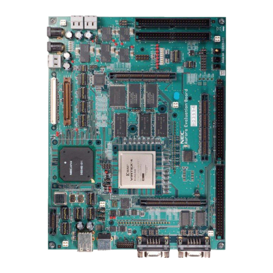
External View of Pfesip EP-1 Evaluation Board
20
Function of each Part
21
Specifications of Pfesip EP-1 Evaluation Board
22
Summarized Block Diagram of Pfesip EP-1 Evaluation Board
23
Detailed Block Diagram of Pfesip EP-1 Evaluation Board
24
Caution Regarding Maximum Operating Frequency of Pfesip/V850Ep1
26
Maximum Operating Frequency of Pfesip/V850Ep1 According to Operating Conditions
26
Overview of Pfesip/V850Ep1
27
Functions of Pfesip/V850Ep1
28
Internal Block Diagram of Pfesip/V850Ep1
30
Chapter 2 Hardware Installation
31
Preface
31
Mounting Pfesip/V850Ep1
31
Operating Mode Setting
31
Mounting Oscillation Module
32
Connecting Power Supply
33
AC Adapter (CN21, CN23)
33
Power Supply Terminal (CN16)
33
And 1.5 V Power Supply Terminal
34
Chapter 3 Switch Settings
35
Operating Mode Setting Dip Switches
35
Operating Mode Settings
35
Operating Mode Settings
36
On-Chip Work RAM (VSB_RAM) Setting
37
SSCG-PLL Operating Mode Setting Dip Switches
39
Chip Select Signal Setting Dip Switches
41
Boot ROM Bank Selection Dip Switches
42
SW_FWP (Flash ROM Boot Block Write Protect)
43
Jumper Settings
44
JP27, JP29 (On-Board SRAM Bus Configuration)
46
JP2 (INTPZ8 Interrupt Signal)
46
JP20 (WAITZ, SELFREFZ, HLDRQZ Jumpers)
47
JP40 (SWAITZ Jumper)
47
JP9-JP11 (Analog Inputs Selection)
48
JP12 to JP14 (Serial Interface JSIO1 Connection)
49
JP15 to JP17 (Serial Interface JSIO2 Connection)
50
JP41, JP42 (USB Interface OCI0, OCI1 Jumpers)
51
JP43 (FPGA DONE Signal Pull-Up Setting Jumper)
51
JP44 (FPGA Configuration ROM Selection Jumper)
51
JP45 (Pfesip/V850Ep1 EV : +3.3 V Power Supply Jumper)
52
JP46 (Pfesip/V850Ep1 IV : +1.5 V Power Supply Jumper)
53
Chapter 4 External Memory Access Setting Example
54
On-Board Memory Specifications
54
External Memory
54
External Memories
54
Internal Memory
55
Setting External Memory Access Operation
56
Register Setting Values
65
Pfesip/V850Ep1 Start Procedure
66
Chapter 5 Using Expansion Connectors
70
AMP MICTOR Connector (CN6, CN7, CN9, CN13, CN14)
71
Supported Plugs
72
Receptacles Used When Stacking Boards
72
Signal Assignment of Connectors
73
CN6 (MICTOR) Pin Layout
73
CN7, CN13 (MICTOR) Pin Layout
74
CN9, CN14 (MICTOR) Pin Layout
75
Simplified Connectors (CN8, CN10)
76
Simplified Connector (General-Purpose 50-Pin) Pin Layout
76
Pfesip/V850Ep1 Port Output Connectors (CN11, CN12)
77
Pfesip/V850Ep1 Ports Connected to CN11 and CN12
77
Pfesip/V850Ep1 P154 to P157 Header (CN15)
78
Simplified Connector (General-Purpose 50-Pin) Pin Layout
78
Pin Headers (CN15) Pin Layout
78
Chapter 6 Emulation Connector
79
N-Wire Interface
79
N-Wire Connector (CN1)
80
ROM Cable Connector (for Midas)
82
SDRAM Bus Tracer Connector (for Advice)
83
Chapter 7 On-Board Large-Capacity Fpga
84
Default FPGA Programming
85
Veriloghdl Source of Default Pfesip/V850Ep1 Data
86
Default FPGA Data
88
FPGA Data Generation Environment
88
File Explanation
88
Explanation of Files Directly under TOP Directory
88
Push Switches for FPGA
89
DIP Switches for FPGA
90
SW12 Operation with Default Program
90
Leds for FPGA
91
LED Operation with Default Program
91
Serial ROM for FPGA
92
Connection of FPGA and Expansion Connectors
93
FPGA Pin Connections
94
Chapter 8 Other Functions
111
Various Leds
111
LED for FPGA (LED1 to LED8)
111
LED Operation with Default Program
111
USB Host Port Leds (LED9, LED10)
112
LED for FPGA DONE (LED11)
112
Power Supply LED (LED12)
112
Serial Connectors
113
USB Function
116
Peripheral Circuit of USB Function Controller
117
Peripheral Circuit of USB Host Controller
118
USB Host Port Leds (LED9, LED10)
118
Analog Input Function
119
Analog Input Terminal
119
Volume Connected to A/D Converter
119
Power Supply Circuit
120
DD : +3.3 V Power Supply
120
Pfesip/V850Ep1
120
DD : +1.5 V Power Supply
120
Manipulation Switches
121
Reset Switch
121
Interrupt Switches
122
Chapter 9 Option Board
123
Connector Conversion Boad
123
Shape of Connector Conversion Board
123
Installing Connector Conversion Boards
124
Signal Assignment of AMP MICTOR and General-Purpose Connectors
125
Appendix Afpga Pin Processing
126
ISE Software User Constraint File (.Ucf)
126
Advertisement
Advertisement
Related Products
Renesas EZ-0011
Renesas EK-RA6M1
Renesas EK-RA2A1 v1
Renesas EK-RA6M5
Renesas EK-RA4E2
Renesas EVK-5P1105ALL
Renesas EU045
Renesas EK-RA8M1
Renesas EK-RA4L1 v1
Renesas EZ-0012
Renesas Categories
Computer Hardware
Motherboard
Microcontrollers
Adapter
Switch
More Renesas Manuals
Login
Sign In
OR
Sign in with Facebook
Sign in with Google
Upload manual
Upload from disk
Upload from URL