Sign In
Upload
Manuals
Brands
RadiSys Manuals
Desktop
EPC-8A
RadiSys EPC-8A Manuals
Manuals and User Guides for RadiSys EPC-8A. We have
1
RadiSys EPC-8A manual available for free PDF download: Hardware Reference Manual
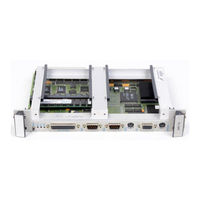
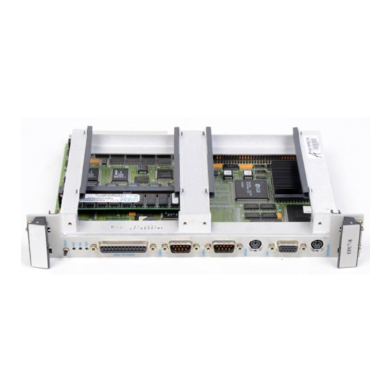
RadiSys EPC-8A Hardware Reference Manual (122 pages)
Highly integrated PC-compatible computer designed specifically for use in the VMEbus and extended VMEbus (VXIbus) environments
Brand:
RadiSys
| Category:
Desktop
| Size: 0 MB
Table of Contents
About this Guide
3
Table of Contents
5
Chapter 1: Product Description
11
Overview
11
Vmebus
12
System Controller Functions
12
Vmebus Master Interface
12
Vmebus Extended Register Set
13
Specifications
13
Table 1-1. EPC-8A Environmental Specifications
13
Table 1-2. Additional EPC-8A Specifications
13
Chapter 2: Configuration and Installation
15
Before You Begin
15
Configuring the EPC-8A
15
Slot-1 Functionality
15
Selecting the EPC-8A Slot Location
16
Figure 2-1. Jumper Locations
16
Installing the Vmebus Backplane Jumpers
17
Figure 2-2. Daisy-Chain Signal Concept
17
Table 2-1. VME Slots Available
17
Figure 2-3. Backplane Jumpers Required for EPC-8A Subsystem
18
EPC-8A Insertion
19
Figure 2-4. Vmebus Jumpers on Rear Wirewrap Pins
19
Figure 2-5. Vmebus Jumpers on Front Stake Pins
19
Connecting Peripherals to the EPC-8A
20
Remaining Steps
20
Chapter 3: BIOS Configuration
21
BIOS Setup Screens
21
Main BIOS Setup Menu
22
Figure 3-1. Main Menu
22
Figure 3-2. IDE Adapter Sub-Menu
23
IDE Adapter Sub-Menus
23
Figure 3-3. Memory Shadow Sub-Menu
25
Memory Cache Sub-Menu
25
Memory Shadow Sub-Menu
26
About Shadow Memory Regions
26
Figure 3-4. Memory Shadow Sub-Menu
26
Boot Sequence Sub-Menu
27
Figure 3-5. Boot Sequence Sub-Menu
27
Figure 3-6. Keyboard Features Sub-Menu
29
Keyboard Features Menu
29
Advanced Menu
30
Figure 3-7. Advanced Menu
30
Figure 3-8. Integrated Peripherals Sub-Menu
32
Integrated Peripherals Sub-Menu
32
EXM Menu
33
Figure 3-9. EXM Menu
33
Figure 3-10. Slot Numbering
34
VME Menu
35
Figure 3-11. VME Menu
35
Exit Menu
36
Figure 3-12. Exit Menu
36
Chapter 4: Theory of Operation
39
Overview
39
Processor Board
40
Processor and Coprocessor
40
Figure 4-1. Block Diagram
40
Memory
41
Memory Map
41
BIOS ROM and ROM Shadowing
41
Table 4-1. Memory at Addresses between 0 and 1MB (0Fffffh)
41
Table 4-2. Extended Memory Address Space for a 4MB EPC-8A
41
CMOS Backup and Restore
42
Video Controller
42
Figure 4-2. Flash Boot Device Memory
42
Ethernet Controller
43
Resident Flash/Sram Memory
43
Resident Flash Memory
43
Sram
43
Watchdog Timer
43
Battery
44
Peripheral Ports
45
RS-232 Port
45
RS-422/485 Port
45
Parallel Port
45
Keyboard
45
Front Panel Leds
45
Resetting the EPC-8A
46
Power-Off, Power-On
46
Power Low
46
Front-Panel Reset Button
46
Table 4-3. Reset Conditions
46
Ctrl+Alt+Del
47
Vmebus SYSRESET
47
Watchdog Timer
47
Register State after Reset
47
VME/VXI Soft RESET State and SYSRESET
47
Signal Register FIFO
48
EXM Expansion Interface
48
VME Interface
49
Connectivity
49
Vmebus System (Slot-1) Controller Functions
49
Vmebus Access
49
Byte Ordering
50
Figure 4-3. Using Little-Endian Byte Ordering
50
Vmebus Interrupt Response
51
VME Extension Registers (VXI)
51
Figure 4-4. Using Big-Endian Byte Ordering
51
Passing VME Interrupts and Events to the CPU
52
Figure 4-5. Passing VME Interrupts and Events to the CPU
52
Chapter 5: Programming the Vmebus Interface
53
Concepts
53
Atomic Access
53
Read-Modify-Write Operations
53
Setting the Vmebus Access Bit
54
Real-Mode "E-Page" Vmebus Accesses
54
Supported Address Modifiers
55
Low-Level Programming "E" Page Accesses
55
Example #1
55
Table 5-1. Supported Address Modifiers
55
Example #2
56
Low-Level Handling of Vmebus Interrupts
57
Start of Loop
58
Protected-Mode Direct Vmebus Accesses
58
Generating Iacks in Protected Mode
59
Table 5-2. VME Access Type
59
Programming the Watchdog Timer
60
Appendix A: Chipset and I/O Map
61
Table A-1. First (8-Bit) DMA Controller: Radisys R400EX Chip Emulating 8237 of PC⁄AT
61
Table A-2. First Interrupt Controller: Radisys R400EX Emulating 8259 of PC/AT
61
Table A-3. R400EX Controller
61
Table A-4. Counter-Timer Functions: Radisys R400EX Emulating 8254 of PC⁄AT
62
Table A-5. Keyboard Port: Radisys R400EX Emulating 8742 of PC/AT
62
Table A-6. Time-Of-Day Clock: Radisys R400EX Emulating MC146818 of PC⁄AT
62
Table A-7. DMA Page Registers: Radisys R400EX Emulating 74LS612 of PC/AT
62
Table A-8. Port a
63
Table A-9. EXM Configuration
63
Table A-10. Second Interrupt Controller: Radisys R400EX Emulating 8259 of PC⁄AT
63
Table A-11. Second (16-Bit) DMA Controller: Radisys R400EX Emulating 8237 of PC⁄AT
63
Table A-12. Coprocessor Interface: for the EPC-8A DX, DX Replaces the 80287 of PC⁄AT
64
Table A-13. EXM Configuration
64
Table A-14. Ethernet
64
Table A-15. Serial I/O (Com2) Port: National Semiconductor PC87336 Emulating 8251 of PC⁄AT
64
Table A-16. Parallel I/O (LPT1) Port: National Semiconductor PC87336 Emulating 8255 of PC⁄AT
64
Table A-17. VGA
64
Table A-18. Serial I/O (Com1) Port: National Semiconductor PC87336 Emulating 8552 of PC/AT
65
Table A-19. EPC Registers
65
Table A-20. VME Registers
65
Table A-21. VXI, Vme/Misc., and On-Board EXM-2A Registers
66
Appendix B: Interrupts and DMA Channels
67
Interrupts
67
Table B-1. Interrupts
67
Table B-2. DMA Channels
67
Appendix C: Connectors
69
Port (COM1)
69
RS-422/485 Port (COM2)
69
Table C-1. DB-9 Pin-Out
69
Table C-2. COM2 RS-422/RS485 Port Pin-Out
69
Parallel Port
70
Keyboard
70
Table C-3. DB-25 Pin-Out
70
Table C-4. Keyboard Pin-Out
70
Vga
71
Ethernet
71
Table C-5. DB-15 Pin-Out
71
Table C-6. RJ45 Phone Jack Pin-Out
71
Appendix D: Memory
73
Memory
73
Appendix E: Subplanes
75
Subplane Installation
75
EXP-BP1 Subplane
75
Figure E-1. EXP-BP1 Subplane
75
EXP-BP2 Subplane
76
Figure E-2. EXP-BP2 Subplane
76
EXP-BP4 Subplane
77
Figure E-3. EXP-BP4 Subplane
77
EXP-BP3A Subplane
78
Figure E-4. EXP-BP3A Subplane
78
EXP-BP5 Subplane
79
Figure E-5. EXP-BP5 Subplane
79
EXP-BP4A Subplane
80
Figure E-6. EXP-BP4A Subplane
80
EXP-BP6 Subplane
81
Figure E-7. EXP-BP6 Subplane
81
Appendix F: Registers
83
Registers Specific to the EPC-8A
83
Configuration (8102H)
84
VME A21-16 Address Register (8130H)
85
ID Register (8140H and 8141H)
85
Device Type Register (8142H and 8143H)
85
Status/Control Register (8144H and 8145H)
85
Reserved (8146H and 8147H)
86
Protocol Register/Signal FIFO (8148H and 8149H)
87
Response Register (814Ah and 814Bh)
87
Reserved (814C and 814D)
89
Message Low Register (814Eh and 814Fh)
89
VME A31-24 Address Register (8150H)
89
VME Modifier Register (8151H)
89
VME Interrupt State Register (8152H)
90
VME Interrupt Enable Register (8153H)
90
VME Event State Register (8154H)
90
VME Event Enable Register (8155H)
90
VME Interrupt Generator Register (8158H)
91
Unique Logical Address Register (815Ch)
91
Module Status/Control Register (815Dh)
91
Vmebus Mapped Registers
92
Appendix G: XFORMAT Software for the EPC-8A
93
XFORMAT Software
93
Appendix H: AUTOSET Software
95
AUTOSET Software
95
Installing the Software
95
Using the AUTOSET Program
95
Figure H-1. AUTOSET Program Main Menu
96
Figure H-2. Manual Configuration Menu
96
Novell Configuration
97
I/O Base Address
97
Adapter Architecture
98
Interrupts
98
Boot PROM
99
Configuring Additional Ethernet Controllers
99
Diagnostics
100
Error Messages
100
Appendix I: SVGA
103
Video Controller Hardware
103
Display Drivers and Utilities
103
Introduction
103
Before You Begin
104
Notational Conventions
104
Easy Installation
104
Windows 95 Installation
104
Windows 3.X Installation
104
Chips and Technologies Web Site
104
Table I-1. Notational Conventions
104
Utility Software
105
Microsoft Windows 3.1
105
Before Upgrading from a Previous Release
105
Microsoft Windows 95
106
Driver Installation Procedure
106
OSR2 Driver Installation Procedure
106
Appendix J: Error Messages and Diagnosis
109
Troubleshooting
109
Table J-1. Troubleshooting Error Messages
109
BIOS Beep Codes
110
Common Error Messages
110
Table J-2. BIOS Troubleshooting Beep Codes
110
Appendix K: Configuring the Ethernet Drivers
115
Netware IPX Driver for DOS Installation
115
ODI Driver for DOS Installation
115
NDIS Driver for DOS Installation
116
Packet Driver Installation
117
Windows NT Driver Installation
117
Index
119
Advertisement
Advertisement
Related Products
RadiSys EPC-2
RadiSys EPC-2e
RadiSys EPC-3208 Series
RadiSys EPC-6320
RadiSys EPC-3307
RadiSys EPC-7
RadiSys EPC-23
RadiSys EPC-3311
RadiSys EPC-32
RadiSys EPC-30
RadiSys Categories
Computer Hardware
Motherboard
Control Unit
Gateway
Single board computers
More RadiSys Manuals
Login
Sign In
OR
Sign in with Facebook
Sign in with Google
Upload manual
Upload from disk
Upload from URL