Sign In
Upload
Manuals
Brands
Quantech Manuals
Chiller
QWC3050T-200T
Quantech QWC3050T-200T Manuals
Manuals and User Guides for Quantech QWC3050T-200T. We have
1
Quantech QWC3050T-200T manual available for free PDF download: Installation Operation & Maintenance
Quantech QWC3050T-200T Installation Operation & Maintenance (186 pages)
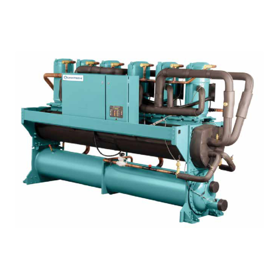
WATER-COOLED LIQUID CHILLERS HERMETIC SCROLL
Brand:
Quantech
| Category:
Chiller
| Size: 10 MB
Table of Contents
Table of Contents
5
Section 1 - General Chiller Information and Safety
11
Introduction
11
Safety
11
Warranty
11
Misuse of Equipment
12
FIGURE 1 - QWC3 Water Cooled Liquid Chiller
13
Condenser
14
Evaporator
14
Microprocessor Control Center
14
Refrigerant Circuit
14
Power Panel
15
Accessories and Options
16
Control / Power Panel Components
18
Section 2 - Product Description
13
Compressors
13
Introduction
13
Refrigerant Circuits
13
FIGURE 2 - Control / Panel Compowwnents
18
FIGURE 4 - Unit Components
20
FIGURE 5 - Control / Power Panel Components Dual System Units
21
TABLE 1 - Product Identification Number
22
Refrigerant Flow
26
Product Identification Number (Pin)
22
FIGURE 3 - Control Power Panel Components
19
Unit Components
20
FIGURE 6 - Refrigerant Flow Diagram
26
FIGURE 7 - Process and Instrumentation Diagram
27
Section 3 - Transportation, Handling and Storage
29
Delivery and Storage
29
Inspection
29
Moving the Unit
29
Lifting Weights
30
FIGURE 8 - Chiller Rigging and Lifting Weights
30
Section 4 - Installation
31
Foundation
31
Installation Checklist
31
Location Requirements
31
Unit Isolation (Noise Sensitive Location)
31
Installation of Vibration Isolators
32
Pipework Connection
32
FIGURE 9 - ANSI/AWWA C-606 - Adapter Flanges
34
Option Flanges
34
Refrigerant Relief Valve Piping
34
Water Treatment
34
Condenser Cooling Liquid Systems
35
FIGURE 11 - Inlet Temperature Control Diagram
35
TABLE 2 - Condenser / Cooler Connections
36
Control Panel Wiring
37
Electrical Connection
37
Field Wiring
37
Power Wiring
38
Compressor Heaters
39
High Pressure Cutout
39
Relief Valves
39
Control Wiring
40
FIGURE 10 - Direct Pressure Control Diagram
35
Connection Types and Sizes
36
Pipework Arrangement
36
Pressure Tapping
36
FIGURE 12 - Chilled Liquid System
36
FIGURE 13 - Condenser Cooling Liquid System
36
FIGURE 14 - Pipework Arrangements Legend
36
FIGURE 15 - Cooler Connections
36
FIGURE 16 - Control Wiring
40
Section 5 - Technical Data
41
Operational Limitations
41
TABLE 3 - Temperatures and Flows
41
TABLE 4 - Voltage Limitations
42
FIGURE 17 - Evaporator Water Pressure Drop Curves
43
FIGURE 18 - Condenser Water Pressure Drop Curves
44
Ethylene and Propolyne Glycol Correction Factors
45
FIGURE 19 - Glycol Solution Strengths
45
TABLE 5 - Ethylene and Propolyne Glycol Correction Factors
45
TABLE 6 - Recommended Glycol Solution Strengths
45
FIGURE 20 - Single Point Power Supply Connection - Standard Unit
60
Dual-Point Supply Connection - Terminal Block, Non-Fused Disconnect Switch or Circuit Breaker
61
FIGURE 21 - Dual Point Power Supply Connection - Standard Unit
61
Electrical Data
62
TABLE 7 - Micro Panel Power Supply
62
TABLE 8 - Voltage Range (Limitations)
62
Electrical Notes and Legend
63
Ground Wire Sizing
64
Elementary Wiring Diagram
66
Physical Data - Standard and High Efficiency
46
Single Point Electrical Data
48
Dual Point Electrical Data
56
Single-Point Supply Connection - Terminal Block, Non-Fused Disconnect Switch or Circuit Breaker
60
Condenser Pressure Drop Charts
44
FIGURE 22 - Control Circuit, 4 Compressor
66
FIGURE 23 - Control Circuit, 5 and 6 Compressor
68
FIGURE 24 - Power Circuit, 4 Compressor with Non Fused Disconnect Switch or Circuit Breaker
70
FIGURE 28 - Connection Wiring Diagram, 4 Compressor
74
FIGURE 29 - Connection Wiring Diagram, 4 Compressor
76
FIGURE 32 - Elementary Wiring Diagram Details, 4 Compressor
82
FIGURE 33 - Elementary Wiring Diagram Details, 5 and 6 Compressor
84
FIGURE 34 - Elementary Wiring Diagram, EEV Controller, 4 and 6 Compressor
86
Unit Dimensions - Four Compressor
87
Unit Dimensions - Five and Six Compressor
89
FIGURE 30 - Connection Wiring Diagram, 5 and 6 Compressor
78
FIGURE 31 - Connection Wiring Diagram, 6 Compressor
80
Elementary Wiring Diagram Details
82
FIGURE 25 - Power Circuit, 4 Compressor with Circuit Breaker
71
FIGURE 26 - Power Circuit, 5 and 6 Compressor
72
FIGURE 27 - Power Circuit, 6 Compressor
73
Connection Wiring Diagram
74
Section 6 - Commissioning
105
Preparation - Power off
105
FIGURE 35 - EEV IB-G Interface Board
106
Preparation - Power on
107
Unit Operating Sequence
111
Section 7 - Unit Controls
113
Introduction
113
Status Key
115
Status Key Messages
120
TABLE 9 - Status Key Messages Quick Reference List
120
TABLE 10 - Operation Data
124
Entry Keys
129
Setpoints Keys
130
Display/Print Keys
121
TABLE 11 - Cooling Setpoints, Programmable Limits and Defaults
132
TABLE 12 - Program Key Limits and Default
135
TABLE 13 - Setpoints Quick Reference List
136
Unit Keys
137
FIGURE 36 - Unit Keys Options Programming Quick Reference List
143
Section 8 - Unit Operation
145
Capacity Control
145
Discharge Pressure Limit Controls
145
Leaving Chilled Liquid Control
145
Suction Pressure Limit Controls
145
FIGURE 37 - Leaving Water Temperature Control Example
146
FIGURE 38 - Setpoint Adjust
146
TABLE 14 - Sample Compressor Staging for Return Water Control
147
Return Chilled Liquid System Lead/Lag and Compressor Sequencing
148
TABLE 15 - Return Chilled Liquid Control for 4 Compressors (6 Steps)
148
TABLE 16 - Return Chilled Liquid Control for 4 Compressors (6 Steps)
148
TABLE 17 - Compressor Operation - Load Limiting
150
Bas/Ems Temperature Reset Using Avoltage or Current Signal
151
Anti-Coincidence Timer
149
Anti-Recycle Timer
149
Evaporator Heater Control
149
Evaporator Pump Control and Hydro Kit Pump Control
149
Load Limiting
149
Pumpdown Control
149
Alarm Status
150
Compressor Run Status
150
Ems-Pwm Remote Temperature Reset
150
Leaving Chilled Liquid Control Override to Reduce Cycling
146
Leaving Chilled Liquid System Lead/Lag and Compressor Sequencing
146
Return Chilled Liquid Control
147
Section 9 - Service and Troubleshooting
153
Clearing History Buffers
153
Service Mode
153
Service Mode - Outputs
153
Inputs
154
Service Mode - Analog and Digital
154
Service Mode - Chiller Configuration
154
Control Inputs/Outputs
155
TABLE 21 - I/O Analog Outputs
155
TABLE 19 - I/O Digital Outputs
155
TABLE 20 - I/O Analog Inputs
155
TABLE 22 - Entering/Leaving Chilled Liquid Temp. Sensor, Temperature / Voltage Correlation
158
TABLE 23 - Pressure Transducers
159
FIGURE 40 - I/O Board Relay Contact Architecture
160
Acceptable Printers
161
Optional Printer Installation
161
Printer Connections
161
Printer Setup
161
Printing a Report
162
Table 24 - Okidata Okipos 441
162
TABLE 25 - Printout Types
162
Troubleshooting
163
FIGURE 39 - Microboard Layout
156
Checking Inputs and Outputs
157
TABLE 18 - I/O Digital Inputs
155
Microboard Layout
156
TABLE 26 - Troubleshooting
163
Section 10 - Maintenance
167
Compressors
167
Important
167
On-Board Battery Back-Up
167
Operating Parameters
167
Overall Unit Inspection
167
Bacnet and Modbus Data Communications
168
FIGURE 41 - Micro Panel Connections
169
TABLE 27 - Values Required for Bas Communication
169
TABLE 28 - Real Time Error Numbers
170
TABLE 29 - BACNET and Modbus Communications Data Map
171
TABLE 30 - Yorktalk 2 Communications Data Map
176
Temperature Conversion Chart
182
Pressure Temperature Chart
183
R410-A
183
Temperature
184
TABLE 31 - si Metric Conversion
184
Advertisement
Advertisement
Related Products
Quantech QWC3
Quantech QTC3150THE
Quantech QTC40180
Quantech QTC40205
Quantech QTC40260
Quantech QTC3095T
Quantech QTC3205T
Quantech QTC4 320
Quantech QTC4 405
Quantech QTC4 410
Quantech Categories
Chiller
Air Compressor
Heat Pump
Adapter
More Quantech Manuals
Login
Sign In
OR
Sign in with Facebook
Sign in with Google
Upload manual
Upload from disk
Upload from URL