Sign In
Upload
Manuals
Brands
Puls Manuals
Power Supply
Dimersion CP10.481
Puls Dimersion CP10.481 Manuals
Manuals and User Guides for Puls Dimersion CP10.481. We have
3
Puls Dimersion CP10.481 manuals available for free PDF download: Manual, Quick Start Manual, Installation Manual
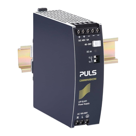
Puls Dimersion CP10.481 Manual (278 pages)
48V, 5.4A, 260W, SINGLE PHASE INPUT
Brand:
Puls
| Category:
Power Supply
| Size: 8 MB
Table of Contents
Table of Contents
2
Intended Use
3
Installation Requirements
3
AC-Input
4
DC-Input
5
Input Inrush Current
6
Output
7
Hold-Up Time
8
DC-OK Relay Contact
9
Efficiency and Power Losses
10
Lifetime Expectancy and MTBF
11
Functional Diagram
12
Terminals and Wiring
13
Front Side and User Elements
14
15. Emc
15
Environment
16
Protection Features
17
Safety Features
17
Dielectric Strength
18
Approvals
19
Other Fulfilled Standards
19
Physical Dimensions and Weight
20
Peak Current Capability
24
Back - Feeding Loads
25
External Input Protection
25
Output Circuit Breakers
25
Parallel Use for Redundancy
26
Series Operation
27
Inductive and Capacitive Loads
27
Charging of Batteries
27
Operation on Two Phases
28
Use in a Tightly Sealed Enclosure
28
Mounting Orientations
29
Intended Use
32
Installation Instructions
32
Power Losses
41
User Elements
43
Protection Features
48
Dimensions and Weight
51
Accessories
52
Uf20.241 Buffer Module
53
Redundancy Modules
53
Application Notes
55
Peak Current Capability
55
Charging of Batteries
57
Series Operation
57
Parallel Use to Increase Output Power
58
Parallel Use for Redundancy
59
Operation on Two Phases
60
Use in a Tightly Sealed Enclosure
60
General Description
62
Order Numbers
62
Intended Use
64
Installation Requirements
65
Hold - up Time
70
Power Losses
71
Safety Features
77
R Ohs, Reach and Other Fulfilled Standards
79
Dimensions and Weight
80
Peak Current Capability
83
Back - Feeding Loads
84
External Input Protection
84
Output Power
84
Series Operation
85
Capacitive Loads
85
Power Supply
87
Order Numbers
87
Intended Use
89
Hold - up Time
94
Power Losses
95
Functional Diagram
96
Front Side and User Elements
96
Dimensions and Weight
104
Mount Bracket
106
Peak Current Capability
108
Output Circuit Breakers
109
Charging of Batteries
109
Series Operation
110
Parallel Use to Increase Output Power
110
Parallel Use for Redundancy
111
Operation on Two Phases
112
Use in a Tightly Sealed Enclosure
113
General Description
115
Order Numbers
115
Intended Use
117
Installation Requirements
117
Hold - up Time
121
Power Losses
122
Functional Diagram
123
Front Side and User Elements
123
Safety Features
127
Dimensions and Weight
130
Peak Current Capability
132
Back - Feeding Loads
132
Parallel Use for Redundancy
134
Series Operation
134
Capacitive Loads
134
Operation on Two Phases
135
Use in a Tightly Sealed Enclosure
136
General Description
138
Order Numbers
138
Intended Use
140
Installation Requirements
140
Hold - up Time
144
Power Losses
145
Functional Diagram
146
Front Side and User Elements
146
Safety Features
150
Dimensions and Weight
153
Peak Current Capability
155
Back - Feeding Loads
155
Charging of Batteries
156
Series Operation
157
Capacitive Loads
157
Operation on Two Phases
158
General Description
161
Order Numbers
161
Intended Use
163
Installation Requirements
163
Hold - up Time
167
Power Losses
168
Functional Diagram
169
Front Side and User Elements
169
Safety Features
173
Dimensions and Weight
176
Peak Current Capability
178
Back - Feeding Loads
178
Charging of Batteries
179
Parallel Use for Redundancy
180
Capacitive Loads
180
Series Operation
180
Operation on Two Phases
181
General Description
184
Order Numbers
184
Intended Use
186
Installation Requirements
186
Hold - up Time
190
Power Losses
191
Functional Diagram
192
Front Side and User Elements
192
Safety Features
196
R Ohs, Reach and Other Fulfilled Standards
198
Dimensions and Weight
199
Peak Current Capability
201
Back - Feeding Loads
201
Capacitive Loads
203
Series Operation
204
Operation on Two Phases
204
Use in a Tightly Sealed Enclosure
205
General Description
207
Order Numbers
207
Intended Use
209
Installation Requirements
209
Hold - up Time
213
Power Losses
214
Front Side and User Elements
215
Safety Features
219
R Ohs, Reach and Other Fulfilled Standards
221
Dimensions and Weight
222
Uf20.241 - Buffer Module
223
Peak Current Capability
224
Back - Feeding Loads
224
Charging of Batteries
225
Capacitive Loads
226
Series Operation
227
Operation on Two Phases
227
Use in a Tightly Sealed Enclosure
228
General Description
232
Order Numbers
232
Intended Use
234
Installation Requirements
234
Hold - up Time
238
Power Losses
239
Safety Features
245
Dielectric Strength
246
Dimensions and Weight
248
Peak Current Capability
250
Back - Feeding Loads
250
Parallel Use for Redundancy
251
Series Operation
252
Charging of Batteries
252
Operation on Two Phases
253
Use in a Tightly Sealed Enclosure
253
Advertisement
Puls Dimersion CP10.481 Quick Start Manual (29 pages)
Brand:
Puls
| Category:
Power Supply
| Size: 0 MB
Table of Contents
Table of Contents
2
Intended Use
3
Installation Requirements
3
AC-Input
4
DC-Input
5
Input Inrush Current
6
Output
7
Hold-Up Time
8
DC-OK Relay Contact
9
Efficiency and Power Losses
10
Lifetime Expectancy and MTBF
11
Functional Diagram
12
Terminals and Wiring
13
Front Side and User Elements
14
15. Emc
15
Environment
16
Protection Features
17
Safety Features
17
Dielectric Strength
18
Approvals
19
Other Fulfilled Standards
19
Physical Dimensions and Weight
20
Accessories
21
ZM4.WALL - Wall/Panel Mount Bracket
21
ZM12.SIDE - Side Mounting Bracket
22
Redundancy Modules
23
Application Notes
24
Peak Current Capability
24
Back-Feeding Loads
25
External Input Protection
25
Output Circuit Breakers
25
Parallel Use to Increase Output Power
26
Parallel Use for Redundancy
26
Series Operation
27
Inductive and Capacitive Loads
27
Charging of Batteries
27
Operation on Two Phases
28
Use in a Tightly Sealed Enclosure
28
Mounting Orientations
29
Puls Dimersion CP10.481 Installation Manual (2 pages)
Power Supply 1-Phase, 48V, 5.4A, 260W
Brand:
Puls
| Category:
Power Supply
| Size: 0 MB
Table of Contents
Product Description
2
Intended Use
2
Installation Instructions
2
Installation Instructions for Hazardous Location Areas
2
Functional Description
2
Technical Data
2
Functional Diagram
2
Output Characteristic
2
Temperature Range
2
Advertisement
Advertisement
Related Products
Puls CP10.241-R2
Puls CP10.241-M1
Puls CP10.242
Puls CP10.241
Puls CP10.241-S1
Puls CP10.242-R2
Puls DIMENSION CP10.122
Puls DIMENSION CP10.241-ETC
Puls DIMENSION CP10.248
Puls DIMENSION CP10.121
Puls Categories
Power Supply
Control Unit
Media Converter
UPS
I/O Systems
More Puls Manuals
Login
Sign In
OR
Sign in with Facebook
Sign in with Google
Upload manual
Upload from disk
Upload from URL