Sign In
Upload
Manuals
Brands
Prusa Research Manuals
3D Printers
Original Prusa i3 MK3S
Prusa Research Original Prusa i3 MK3S Manuals
Manuals and User Guides for Prusa Research Original Prusa i3 MK3S. We have
1
Prusa Research Original Prusa i3 MK3S manual available for free PDF download: Assembly Instructions Manual
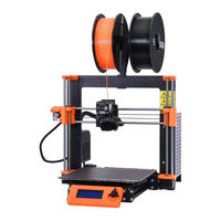
Prusa Research Original Prusa i3 MK3S Assembly Instructions Manual (112 pages)
Brand:
Prusa Research
| Category:
3D Printers
| Size: 28 MB
Table of Contents
Table of Contents
1
Introduction
7
STEP 1 All the Required Tools Are Included
8
STEP 2 Labels Guide
8
STEP 3 Use Labels for Reference
8
STEP 4 Spare Bag
9
STEP 5 View High Resolution Images
9
STEP 6 Printed Parts - Versioning
10
STEP 7 We Are here for You
10
STEP 8 Pro Tip: Inserting the Nuts
10
STEP 9 Important: Electronics Protection
11
STEP 10 Reward Yourself
11
Step 11 - How to Successfully Finish the Assembly
11
Y-Axis Assembly
12
STEP 1 Tools Necessary for this Chapter
13
STEP 2 YZ Frame - Preparing the Components
13
STEP 3 YZ Frame - Mounting the Longer Extrusions
13
STEP 4 YZ Frame - Mounting the Shorter Extrusions
14
STEP 5 YZ Frame - Final Check
14
STEP 6 Y-Axis: Front and Rear Plate Preparation
14
STEP 7 Y-Axis: Front Plate Assembly
15
STEP 8 Y-Axis: Preparation for the PSU
15
STEP 9 Y-Axis: Rear Plate Assembly
15
STEP 10 Y-Axis: Geometry Check
16
Step 11 - Mounting Antivibration Feet (Optional)
16
STEP 12 Preparing Y-Belt-Idler (Part 1)
16
STEP 13 Preparing Y-Belt-Idler (Part 2)
17
STEP 14 Preparing Y-Belt-Idler (Part 3)
17
STEP 15 Mounting the Y-Belt-Idler
18
STEP 16 Y-Axis: Motor and Motor Holder
18
STEP 17 Preparing Y-Motor-Holder
18
STEP 18 Mounting Y-Motor-Holder
19
STEP 19 Y-Axis: Y-Carriage
19
STEP 20 Correct Bearing Orientation
19
STEP 21 Installing Bearings on the Y-Carriage
20
STEP 22 Inserting Smooth Rods into Y-Carriage
20
STEP 23 Y-Axis: Smooth Rods Holders
20
STEP 24 Preparing Y-Rod-Holder
21
STEP 25 Mounting the Y-Rod-Holder Parts
21
STEP 26 Installing the Y-Carriage
21
STEP 27 Aligning the Smooth Rods
21
STEP 28 Assembling the Y-Motor Pulley
22
STEP 29 Y-Axis: Assembling the Belt
22
Step 30 - Y-Axis: Assembling the Belt
22
STEP 31 Y-Axis: Assembling the Belt
23
STEP 32 Y-Axis: Assembling the Belt
23
Step 33 - Y-Axis: Assembling the Belt
23
Step 34 - Y-Axis: Assembling the Belt
24
STEP 35 Aligning the Y-Axis Belt
24
STEP 36 Tensioning the Y-Axis Belt
24
STEP 37 Testing the Y-Axis Belt
25
STEP 38 Haribo Time
25
STEP 39 Y-Axis Is Finished
26
X-Axis Assembly
27
STEP 1 Tools Necessary for this Chapter
28
STEP 2 X-Axis: X-End Idler and Motor Holder
28
STEP 3 X-Axis: X-End Idler and Motor Holder
29
STEP 4 X-Axis: Inserting Linear Bearings
29
STEP 5 X-End-Motor: Tensioner Assembly
29
STEP 6 X-End-Idler: Bearing Assembly
30
STEP 7 X-Axis: Smooth Rods Preassembly
30
STEP 8 Marking the Bearings
30
STEP 9 X-Axis: Assembly
31
STEP 10 Assembling the X-Axis Motor Pulley (Part 1)
31
STEP 11 Assembling the X-Axis Motor Pulley (Part 2)
31
STEP 12 X-Axis: Assembling the Motor
32
STEP 13 Haribo Time
32
STEP 14 X-Axis Is Finished
33
Z-Axis Assembly
34
STEP 1 Tools Necessary for this Chapter
35
STEP 3 Placing the Z-Screw Covers
35
STEP 5 X-Axis: Trapezoidal Nuts (Part 1)
36
STEP 6 X-Axis: Trapezoidal Nuts (Part 2)
36
STEP 7 Assembling the X-Axis and Smooth Rods
37
STEP 8 Placing the Z-Axis-Top Parts (Part 1)
37
STEP 9 Placing the Z-Axis-Top Parts (Part 2)
37
STEP 10 Haribo Time
38
Step 11 - Z-Axis Is Finished
38
E-Axis Assembly
39
STEP 1 Tools Necessary for this Chapter
40
Step 3 - Extruder-Body Parts Preparation
41
Step 4 - Extruder-Body Parts Preparation
41
STEP 5 Extruder-Body Assembly
41
STEP 6 FS-Lever Assembly
42
STEP 7 Steel Ball Assembly
42
STEP 8 Extruder Motor Parts Preparation
42
STEP 9 Bondtech Gear Assembly
43
STEP 10 Bondtech Gear Alignment
43
Step 11 - Extruder-Cover Part Preparation
43
STEP 12 Hotend Parts Preparation
44
STEP 13 Hotend Assembly
44
STEP 14 Extruder Assembly
44
STEP 15 X-Carriage Parts Preparation
45
STEP 16 X-Carriage Assembly
45
STEP 17 Assembling the IR-Sensor Cable
45
STEP 18 Assembling the X-Carriage
46
Step 19 - Assembling the X-Carriage
46
STEP 20 IR-Sensor Parts Preparation
46
Step 21 - IR-Sensor Assembly
47
Step 22 - IR-Sensor Assembly
47
Step 23 - Hotend Fan Parts Preparation
47
Step 24 - Hotend Fan Parts Preparation (Version A)
48
STEP 25 Hotend Fan Cable Adjustment (Version A)
48
Step 27 - Hotend Fan Assembly (Version A)
49
STEP 28 Hotend Fan Parts Preparation (Version B)
49
STEP 29 Hotend Fan Cable Adjustment (Version B)
49
STEP 30 Hotend Fan Assembly (Version B)
50
STEP 31 Hotend Fan Assembly (Version B)
50
STEP 32 Extruder-Idler Parts Preparation (both Fan Versions)
50
STEP 33 Bearing Assembly
51
STEP 34 Extruder-Idler Assembly
51
STEP 35 Filament Alignment Check
51
STEP 36 Extruder-Idler Mounting
52
STEP 37 FS-Cover Parts Preparation
52
STEP 38 FS-Cover Assembly
53
STEP 40 Print-Fan-Support Parts Preparation
54
STEP 41 Print-Fan-Support Assembly
54
STEP 42 Fan-Shroud Parts Preparation (both Fan Versions)
54
STEP 43 Fan-Shroud Assembly (both Fan Versions)
55
STEP 44 Print Fan Parts Preparation
55
STEP 45 Print Fan Assembly
55
STEP 46 Superpinda Sensor Parts Preparation
56
STEP 48 Extruder Parts Preparation
57
STEP 49 Extruder Preparation and Mounting
57
STEP 50 Extruder Channels Cable Management
57
STEP 51 X-Axis Belt Parts Preparation
58
STEP 52 X-Axis Belt Assembly
58
STEP 53 X-Axis Belt Assembly
58
STEP 54 X-Axis Belt Assembly
59
STEP 56 Aligning the X-Axis Belt
60
STEP 57 Testing the X-Axis Belt
60
STEP 58 Trimming the X-Axis Belt
60
STEP 59 Fine Tuning the X-Axis Belt
61
STEP 60 Nylon Guide Parts Preparation
61
STEP 61 Nylon Guide Assembly
61
STEP 62 X-Carriage-Back Parts Preparation
62
STEP 63 Cable-Holder Assembly
62
STEP 64 X-Carriage-Back Assembly
62
STEP 65 Mounting the X-Carriage-Back
63
Step 66 - X-Carriage-Back Assembly
63
STEP 67 Textile Sleeve Parts Preparation
63
STEP 68 Tightening the Textile Sleeve
64
STEP 70 Tightening the Hotend Cables
64
STEP 71 Haribo Time
65
STEP 72 E-Axis Is Finished
65
LCD Assembly
66
STEP 1 Tools Necessary for this Chapter
67
STEP 2 Preparing the LCD Parts
67
STEP 3 Checking the LCD Cables
68
STEP 4 Assembling the LCD Supports
68
STEP 7 Preparing the Supports for Assembly
69
STEP 8 Mounting the LCD Display Onto the Printer
69
STEP 9 Assembling the LCD Knob
70
STEP 10 Haribo Time
70
STEP 11 LCD Is Done
71
Heatbed & PSU Assembly
72
STEP 1 Tools Necessary for this Chapter
73
STEP 2 Heatbed Cable Assembly (Part 1)
73
STEP 3 Heatbed Cable Assembly (Part 2)
73
STEP 4 Heatbed Cable Assembly (Part 3)
74
STEP 5 Preparing the Heatbed
74
STEP 6 Preparing the Heatbed-Cable-Cover
74
Step 7 - Mounting the Heatbed-Cable-Cover
75
Step 8 - Mounting the Heatbed-Cable-Cover
75
STEP 9 Proper Cable Management
75
STEP 10 Wrapping the Heatbed Cables
76
STEP 11 Securing the Sleeve in Place
76
STEP 12 Finalizing the Wrap
76
STEP 13 Preparing the Heatbed Screws and Spacers
77
STEP 14 Mounting the Heatbed (Part 1)
77
STEP 15 Mounting the Heatbed (Part 2)
77
STEP 16 Mounting the Heatbed (Part 3)
78
STEP 17 Mounting the Heatbed (Part 4)
78
STEP 18 Preparing the PSU Parts
78
Step 19 - Assembling the PSU
79
Step 20 - Assembling the PSU
79
STEP 21 Connecting the Power Cables (CRITICAL)
79
STEP 22 Connecting the Power Cables
80
STEP 23 Connecting the Power Cables
80
STEP 24 Connecting the Power Panic
80
STEP 25 Haribo Time
81
STEP 26 Heatbed and PSU Are Done
81
Electronics Assembly
82
STEP 2 Preparing the Einsy-Door (Part 1)
83
Step 3 - Preparing the Einsy-Door (Part 2)
83
STEP 4 Identifying Mount Holes
84
STEP 5 Preparing the Lower Hinge
84
STEP 6 Einsy-Door Assembly
84
STEP 7 Wrapping X-Axis Cable
85
STEP 8 Preparing the Einsy-Base (Part 1)
85
STEP 9 Preparing the Einsy-Base (Part 2)
85
Step 11 - Preparing the Einsy-Base (Part 4)
86
STEP 12 Mounting the Einsy-Base (Part 1)
86
STEP 13 Mounting the Einsy-Base (Part 2)
87
STEP 14 Mounting the Einsy-Base (Part 3)
87
STEP 15 Cable Management (Part 1)
87
STEP 16 Cable Management (Part 2)
88
STEP 18 Cable Management (Part 4)
88
STEP 19 Cable Management (Part 5)
89
STEP 20 Cable Management (Part 6)
89
STEP 21 Cable Management (Part 7)
89
STEP 22 Connecting Cable Bundles
90
STEP 23 Connecting the Heatbed Cable Bundle
90
STEP 25 PSU and HB Power Cables
91
STEP 26 PSU and HB Power Cables
91
STEP 27 Preparing the PSU Cover
91
STEP 28 PSU and HB - Final Check
92
STEP 30 Connecting the Extruder Cable Bundle
92
STEP 31 Wrapping the Cable Bundle
93
Step 32 - Connecting the Extruder Cable Bundle
93
STEP 33 Connecting the LCD Cables
93
STEP 34 Connecting the Motor Cables
94
STEP 35 Preparing the Zip Ties
94
STEP 37 Hotend Cable Guiding (Part 2)
95
STEP 38 Verify All Connections Once more
95
STEP 39 Finalizing the Einsy-Case
95
STEP 41 Assembling the Double Spool Holder (Part 1)
96
STEP 42 Assembling the Double Spool Holder (Part 2)
96
STEP 43 Mounting the Double Spool Holder
97
STEP 44 Attaching the Silver Label
97
STEP 45 Haribo Time
97
STEP 46 Hooray
98
Preflight Check
99
STEP 1 Superpinda Adjustment (Part 1)
100
STEP 2 Superpinda Adjustment (Part 2)
100
STEP 3 Superpinda Adjustment (Part 3)
100
STEP 4 Quick Guide for Your First Prints
101
STEP 5 Printable 3D Models
101
STEP 6 Prusa Knowledge Base
102
STEP 7 Join Printables
102
STEP 8 Haribo Time
102
Manual Changelog MK3S+ Kit
103
STEP 1 Versions History
104
Step 2 - Changes to the Manual
104
Step 3 - Changes to the Manual
104
Step 4 - Changes to the Manual
105
Advertisement
Advertisement
Related Products
Prusa Research Original Prusa MINI
Prusa Research Original Prusa XL
Prusa Research ORIGINAL i3 MK3S+
Prusa Research Original Prusa XL Enclosure
Prusa Research CORE ONE
Prusa Research CORE One Conversion kit
Prusa Research CORE One kit
Prusa Research ESP32-CAM
Prusa Research i3
PRUSA Research i3 MK2
Prusa Research Categories
3D Printers
Enclosure
Digital Camera
Safety Equipment
More Prusa Research Manuals
Login
Sign In
OR
Sign in with Facebook
Sign in with Google
Upload manual
Upload from disk
Upload from URL