Sign In
Upload
Manuals
Brands
Prusa Research Manuals
3D Printers
CORE One kit
Prusa Research CORE One kit Manuals
Manuals and User Guides for Prusa Research CORE One kit. We have
1
Prusa Research CORE One kit manual available for free PDF download: Manual
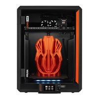
Prusa Research CORE One kit Manual (216 pages)
Brand:
Prusa Research
| Category:
3D Printers
| Size: 42 MB
Table of Contents
Table of Contents
1
Introduction
9
ÉTAPE 1 Preparing the Kit
10
ÉTAPE 2 Comment Naviguer Dans le Manuel
10
ÉTAPE 3 Voir les Images en Haute Résolution
11
ÉTAPE 4 Tous les Outils Nécessaires Sont Inclus
11
ÉTAPE 5 Utilitaires Supplémentaires pour Ce Guide
12
ÉTAPE 6 Labels Guide
12
ÉTAPE 7 Spare Bag
13
ÉTAPE 8 Pièces Imprimées - Versionnage
13
ÉTAPE 9 Nous Sommes Là pour Vous
14
ÉTAPE 10 Astuce de Pro : Insertion des Écrous
15
ÉTAPE 11 Important: Electronics Protection
16
ÉTAPE 12 Reward Yourself
17
ÉTAPE 13 Comment Réussir L'assemblage
18
ÉTAPE 14 Prepare Your Desk
19
Assemblage de la Base
20
ÉTAPE 1 Outils Nécessaires pour Ce Chapitre
21
ÉTAPE 2 Base Assembly: Parts Preparation
21
ÉTAPE 3 Inserting the Zip Ties
22
ÉTAPE 4 Base Assembly: Parts Preparation
22
ÉTAPE 5 Installing the Motor Mounts
23
ÉTAPE 6 Installing the Rear Motor
23
ÉTAPE 7 Securing the Rear Motor
24
ÉTAPE 8 Installing the Front Motor Right
24
ÉTAPE 9 Installing the Front Motor Left
25
ÉTAPE 10 Bottom Frame: Parts Preparation
25
ÉTAPE 11 Assembling the Bottom Profile: Front + Left
26
ÉTAPE 12 Assembling the Bottom Profile: Left + Rear
26
ÉTAPE 13 Assembling the Bottom Profile: Right
27
ÉTAPE 14 Inserting the Spacer Pins
27
ÉTAPE 15 Anti-Vibration Feet: Parts Preparation
28
ÉTAPE 16 Installing the Anti-Vibration Feet
28
ÉTAPE 17 Installing the Bottom Frame
29
ÉTAPE 18 Mounting the Bottom Frame: Right Side
29
ÉTAPE 19 Mounting the Bottom Frame: Rear + Left + Front
30
ÉTAPE 20 Haribo Time
30
ÉTAPE 21 Done
31
Assemblage de L'arrière
32
ÉTAPE 1 Outils Nécessaires pour Ce Chapitre
33
ÉTAPE 2 Assemblage du Bloc D'alimentation : Préparation des Pièces
33
ÉTAPE 3 Preparing the PSU
34
ÉTAPE 4 Power Cables Info
35
ÉTAPE 5 Connecting the PSU
36
ÉTAPE 6 Xbuddy: Parts Preparation I
36
Étape 7 - Xbuddy: Parts Preparation II
37
ÉTAPE 8 Application des Pads Thermiques
38
ÉTAPE 9 Installing the Xbuddy
39
ÉTAPE 10 Installing the Xbuddy Extension
39
ÉTAPE 11 Installing Zip Ties
40
ÉTAPE 12 Connecting the Xbuddy Extension Board
40
ÉTAPE 13 Inserting Grommets: Xbuddy Box
41
ÉTAPE 14 Wi-Fi: Parts Preparation
41
ÉTAPE 15 Assembling the Wi-Fi
42
ÉTAPE 16 Installing the Wi-Fi Assembly
42
ÉTAPE 17 Back Panel: Parts Preparation
43
ÉTAPE 18 Installing Grommets: Back Panel Top
43
ÉTAPE 19 Installing Grommets: Sides + Bottom
44
ÉTAPE 20 Aligning the PSU
44
ÉTAPE 21 Mounting the PSU
45
ÉTAPE 22 Aligning the Xbuddy Box Assembly
45
ÉTAPE 23 Montage du Boîtier de la Xbuddy
46
ÉTAPE 24 Power Cables Cover: Parts Preparation
46
ÉTAPE 25 Connexion des Câbles D'alimentation
47
ÉTAPE 26 Preparing the PSU-Cable-Cover
48
ÉTAPE 27 Gainage des Câbles du Bloc D'alimentation
48
ÉTAPE 28 Chamber Fans: Parts Preparation
49
ÉTAPE 29 Assembling the Fan Grid
50
ÉTAPE 30 Attaching the Fans
51
ÉTAPE 31 Covering the Cooling Fans
51
ÉTAPE 32 Rear Profiles: Parts Preparation
52
ÉTAPE 33 Installing the Rear Profiles
52
ÉTAPE 34 Mounting the Back Panel
53
ÉTAPE 35 Stepper Splitter: Parts Preparation
53
ÉTAPE 36 Guiding the Stepper Splitter Cable
54
ÉTAPE 37 Connecting the Stepper Splitter
54
ÉTAPE 38 Mounting the Stepper Splitter
55
ÉTAPE 39 Câble du LCD : Préparation des Pièces
55
ÉTAPE 40 Guidage du Câble du LCD
56
ÉTAPE 41 Main FE Cable INFO
56
ÉTAPE 42 Connecting the FE Cable (no 3.)
57
ÉTAPE 43 Guiding the FE Cable (No. 2)
57
ÉTAPE 44 Guiding the FE Cable (No. 1)
58
ÉTAPE 45 Guiding the FE Cable (No. 4 and 5)
58
ÉTAPE 46 FE Cable - Xbuddy: Parts Preparation
59
ÉTAPE 47 Connecting the FE Cable: Xbuddy
59
ÉTAPE 48 Plugging the Xlcd Cable
60
ÉTAPE 49 PSU-Cover: Parts Preparation
60
ÉTAPE 50 Connecting the FE Cable: PSU
61
ÉTAPE 51 Haribo Time
61
ÉTAPE 52 Done
62
Assemblage du Plateau Chauffant
63
ÉTAPE 1 Outils Nécessaires pour Ce Chapitre
64
Étape 2 - Heatbed: Parts Preparation
65
ÉTAPE 4 Assemblage du Câble du Plateau Chauffant (Partie 2)
66
ÉTAPE 5 Bed-Cable-Cover-Bottom: Parts Preparation
66
ÉTAPE 6 Attaching the Cable Cover
67
ÉTAPE 7 Heatbed Carriage: Parts Preparation
67
Étape 8 - Preparing the Heatbed Carriage
68
Étape 9 - Installing the Expansion Joints
68
ÉTAPE 10 RGB LED Strip: Parts Preparation
69
ÉTAPE 11 Installing the LED Strip
69
ÉTAPE 12 Attaching the LED Strip Diffuser
70
ÉTAPE 13 Covering the RGB LED Strip
70
ÉTAPE 14 Guiding the RGB LED Strip Cable
71
ÉTAPE 15 Bed Mounts: Parts Preparation
71
ÉTAPE 16 Assembling the Bed Mounts
72
ÉTAPE 17 Securing the Bed Mounts
72
ÉTAPE 18 Bed Mounts: Inserting the Nuts
73
ÉTAPE 19 Assembling the CORE-One-Bed-Spacer-Rear
73
ÉTAPE 20 Installing the Bed-Mount-Right
73
ÉTAPE 21 Installing the Bed-Mount-Left
74
ÉTAPE 22 Mounting the Heatbed: Parts Preparation
74
ÉTAPE 23 Mounting the Heatbed
75
ÉTAPE 24 Tightening the Heatbed
75
ÉTAPE 25 Covering the Cables: Parts Preparation
76
ÉTAPE 26 Guidage des Câbles du Plateau Chauffant
76
ÉTAPE 27 Recouvrement des Câbles du Plateau Chauffant
77
ÉTAPE 28 Mounting the Heatbed: Parts Preparation
77
ÉTAPE 29 Attaching the Heatbed Assembly
78
ÉTAPE 30 Mounting the Heatbed Assembly: Rear Motor
79
ÉTAPE 31 Mounting the Heatbed Assembly: Front Motor Left
79
ÉTAPE 32 Mounting the Heatbed Assembly: Front Motor Right
80
ÉTAPE 33 Attaching the Heatbed Cables I
80
ÉTAPE 35 Securing the Heatbed Cables: Parts Preparation
81
ÉTAPE 36 Securing the Textile Sleeve
82
ÉTAPE 37 Guiding the Heatbed Assembly Cables
82
ÉTAPE 38 Connecting the Heatbed Power Cables
83
ÉTAPE 39 Haribo Time
83
ÉTAPE 40 Done
84
Assemblage du Corexy
85
ÉTAPE 1 Outils Nécessaires pour Ce Chapitre
86
ÉTAPE 2 Rod Holders: Parts Preparation
86
ÉTAPE 3 Assembling the Rod Holders
87
ÉTAPE 4 Preparing the Front Rod Holders
87
ÉTAPE 5 Installing the Front Rod Holders
88
ÉTAPE 6 XY Carriage: Parts Preparation
88
ÉTAPE 7 Assembling the XY-Carriages
89
ÉTAPE 8 Assembling the Linear Holder Left
89
ÉTAPE 9 Assembling the Linear Holder Right
90
ÉTAPE 10 Attaching the Linear Holder Assemblies
90
ÉTAPE 11 Smooth Rods INFO
91
ÉTAPE 12 Mounting the Smooth Rods
91
ÉTAPE 13 Securing the Rear Rod Holders
92
ÉTAPE 14 Securing the Front Rod Holders
92
ÉTAPE 15 Motor Mounts: Parts Preparation
93
ÉTAPE 16 Motor Mounts: Part Preparation
93
ÉTAPE 17 Assembling the XY-Motor-Mount-Right I
94
ÉTAPE 19 Assembling the XY-Motor-Mount-Left I
95
ÉTAPE 21 Belt Tensioners: Parts Preparation I
96
Étape 22 - Belt Tensioners: Parts Preparation II
96
ÉTAPE 23 Assembling the Belt Tensioner Left I
96
ÉTAPE 25 Assembling the Belt Tensioner Right
97
ÉTAPE 26 Installing the Belt Tensioners: Parts Preparation
98
ÉTAPE 27 Installing the Motor Mount Right
98
ÉTAPE 28 Installing the Motor Mount Left
99
ÉTAPE 29 Installing the Belt-Tensioner-Left
99
ÉTAPE 30 Installing the Belt-Tensioner-Right
100
ÉTAPE 31 Linear Rail: Parts Preparation
100
ÉTAPE 32 Attaching the Linear Rail
101
ÉTAPE 33 Securing the Linear Rail
101
ÉTAPE 34 Installing the Linear Rail: Parts Preparation
102
ÉTAPE 35 Installing the Linear Rail Assembly
102
ÉTAPE 36 Linear Rail: Removing the Safety Pins
103
ÉTAPE 37 Bed-Stop: Parts Preparation
103
ÉTAPE 38 Assembling the Bed-Stop
103
ÉTAPE 39 Mounting the Bed-Stop
104
ÉTAPE 40 X&Y Motors: Parts Preparation
104
ÉTAPE 41 Installing the X-Axis Pulley
105
ÉTAPE 42 Installing the Y-Axis Pulley
106
ÉTAPE 43 XY Belts: Parts Preparation
106
ÉTAPE 44 XY Belts INFO
107
ÉTAPE 45 y Belt Guiding: y Motor Pulley
107
ÉTAPE 46 Securing the Y-Axis Motor
108
ÉTAPE 47 y Belt Guiding: y Motor Mount
108
ÉTAPE 48 y Belt Guiding: Belt Tensioner
109
ÉTAPE 49 y Belt Guiding: X Motor Mount
109
ÉTAPE 50 y Belt Guiding: Securing the Belt
110
ÉTAPE 51 X Belt Guiding: X Motor Pulley
110
ÉTAPE 52 Securing the X-Axis Motor
111
ÉTAPE 53 y Belt Guiding: X Motor Mount
111
ÉTAPE 54 X Belt Guiding: Belt Tensioner
112
ÉTAPE 55 X Belt Guiding: y Motor Mount
112
ÉTAPE 56 X Belt Guiding: Securing the Belt
113
ÉTAPE 57 Checking the Belt Guidance
113
ÉTAPE 58 Bowden Guide: Parts Preparation
113
ÉTAPE 59 Securing the y Motor Cable
114
ÉTAPE 60 Securing the X Motor Cable
114
ÉTAPE 61 Installing the Bowden Guide
115
ÉTAPE 62 Securing the Nextruder Holder
115
ÉTAPE 63 Bande LED Blanche : Préparation des Pièces
116
ÉTAPE 64 Sticking the White LED Strip
116
ÉTAPE 65 Installing the White LED Assembly
117
ÉTAPE 66 Door Sensor & White LED Strip: Parts Preparation
117
ÉTAPE 67 Inserting the Zip Ties
118
ÉTAPE 68 Installing the Door Sensor
118
ÉTAPE 69 Securing the Door Sensor Cable
119
ÉTAPE 70 Guiding the Cables: LED and Door Sensor
119
ÉTAPE 71 Smooth Rods: Parts Preparation
120
ÉTAPE 72 Installation de L'assemblage du Corexy
120
ÉTAPE 73 Securing the Smooth Rods
121
ÉTAPE 74 Aligning the Linear Rail
121
ÉTAPE 75 Guiding the Corexy Cables
122
ÉTAPE 76 Guiding the Cooling Fan Cables
122
ÉTAPE 77 Fixing the Bed-Stop
123
ÉTAPE 78 Connecting the Cooling Fans Cables
123
ÉTAPE 79 Connecting the Corexy Cables
124
ÉTAPE 80 Haribo Time
124
ÉTAPE 81 Done
125
Assemblage du Nextruder
126
ÉTAPE 1 Tool Necessary for this Chapter
127
ÉTAPE 2 Assemblage de L'idler du Nextruder : Préparation des Pièces
127
ÉTAPE 3 Assemblage de L'idler de L'extrudeur
128
ÉTAPE 4 Assemblage de L'extrudeur : Préparation des Pièces I
128
Étape 5 - Assemblage de L'extrudeur : Préparation des Pièces II
129
ÉTAPE 6 Assembling the Extruder
129
ÉTAPE 7 Assembling the Gearbox
130
ÉTAPE 8 Assembling the PG-Ring
131
ÉTAPE 9 Assembling the PG-Assembly
131
ÉTAPE 10 Checking the PG-Assembly
132
ÉTAPE 11 Assemblage de L'ilder du Nextruder
132
ÉTAPE 12 Lubrification des Engrenages : Préparation des Pièces
133
ÉTAPE 13 Lubricating the Gear
133
ÉTAPE 14 Recouvrement de L'engrenage Planétaire
134
Étape 15 - Assemblage de L'idler-Swivel : Préparation des Pièces
134
ÉTAPE 16 Assembling the Idler-Swivel
135
ÉTAPE 17 Assembling the Idler-Nut
135
ÉTAPE 18 Montage de L'assemblage de L'idler-Swivel
136
ÉTAPE 19 NTC Thermistor: Parts Preparation
136
ÉTAPE 20 Assemblage de la Thermistance NTC
137
ÉTAPE 21 Mounting the Nextruder: Parts Preparation
137
ÉTAPE 22 Protecting the Heatbed
138
ÉTAPE 23 Mounting the Nextruder
138
ÉTAPE 24 Heatsink Fan: Parts Preparation
139
ÉTAPE 25 Installing the Heatsink Fan
139
ÉTAPE 26 Guiding the Heatsink Fan Cables
140
ÉTAPE 27 Loveboard: Parts Preparation I
140
Étape 28 - Loveboard: Parts Preparation II
141
ÉTAPE 29 Assembling the Loveboard-Mount
141
ÉTAPE 30 Assembling the Printhead-Cover
142
ÉTAPE 31 Assembling the Loveboard
142
ÉTAPE 32 Guiding the Main Cable
143
ÉTAPE 33 Covering the Loveboard
143
ÉTAPE 34 Swingarm: Parts Preparation I
144
Étape 35 - Swingarm: Parts Preparation II
144
ÉTAPE 36 Guiding the Main Cable
145
ÉTAPE 37 Mounting the Main Cable
145
ÉTAPE 38 Attaching the Loveboard Assembly
146
ÉTAPE 39 Mounting the Swingarm
146
ÉTAPE 40 Attaching the Main Cable
147
ÉTAPE 41 Insertion du Tube PTFE
147
ÉTAPE 42 Securing the PTFE Tube
148
ÉTAPE 43 Checking the Movement
148
ÉTAPE 44 Print Fan: Parts Preparation
149
ÉTAPE 45 Assembling the Fan-Shroud
149
ÉTAPE 46 Installing the Print Fan Assembly
150
ÉTAPE 47 Hotend: Parts Preparation
150
ÉTAPE 48 Installing the Hotend
151
ÉTAPE 49 Connecting the Heatsink Cables
151
ÉTAPE 50 Connexion des Câbles de la Hotend
152
ÉTAPE 51 Connecting the Print Fan Cable
152
ÉTAPE 52 Connect E-Motor Cable
152
ÉTAPE 53 Loveboard Covers: Parts Preparation
153
ÉTAPE 54 Loveboard: Wiring Check
153
ÉTAPE 55 Covering the Loveboard
154
ÉTAPE 56 Guiding the Main Cable
154
ÉTAPE 57 Haribo Time
155
ÉTAPE 58 Done
155
Carrosserie & Électronique
156
ÉTAPE 1 Outils Nécessaires pour Ce Chapitre
157
ÉTAPE 2 Front Profiles: Parts Preparation
157
ÉTAPE 3 Installing the Front Right Profile
158
ÉTAPE 4 Installing the Front Left Profile
158
ÉTAPE 5 Top Profiles: Parts Preparation
159
ÉTAPE 6 Assembling the Top Profiles I
159
Étape 7 - Assembling the Top Profiles II
160
ÉTAPE 8 Aligning the Top Profiles
160
Étape 9 - Installing the Top Profiles
161
Étape 10 - Corexy Fixing Screws: Parts Preparation
161
ÉTAPE 11 Fixing the Corexy Assembly
162
ÉTAPE 12 Side Sensor Base: Parts Preparation
162
ÉTAPE 13 Assembling the Side Sensor Base
163
ÉTAPE 14 Testing the Lever
163
ÉTAPE 15 Installing the Magnets
164
ÉTAPE 16 IR Sensor: Parts Preparation
164
ÉTAPE 17 Connecting the IR Sensor
165
ÉTAPE 18 Installing the IR Sensor
165
ÉTAPE 19 Installing the Side Sensor Cover
166
ÉTAPE 20 Side Filament Sensor: Parts Preparation
166
ÉTAPE 21 Installing the Side Filament Sensor
167
ÉTAPE 22 Guide the Filament Sensor Cable
167
ÉTAPE 23 Connecting the Side Filament Sensor
168
ÉTAPE 24 NFC Antenna: Parts Preparation
168
ÉTAPE 25 Applying the Adhesive Film
169
ÉTAPE 26 Installing the NFC Coil
169
Étape 27 - Connecting the NFC Coil
170
Étape 28 - Preparing the Electronics Cover
170
ÉTAPE 29 Installing the Electronics Cover
171
ÉTAPE 30 Capot de la Xbuddy : Préparation des Pièces
171
ÉTAPE 31 Installing the Xbuddy Cover
172
ÉTAPE 32 Installing the Rear Cover
172
ÉTAPE 33 Right Side: Parts Preparation
173
ÉTAPE 34 Installing the Spool Holder
173
ÉTAPE 35 Right Handle: Parts Preparation
174
ÉTAPE 36 Installing the Collet
174
ÉTAPE 37 Mounting the Handle
175
ÉTAPE 38 Fixing the Right Side
175
ÉTAPE 39 Left Side: Parts Preparation
176
ÉTAPE 40 Installing the Left Side
176
ÉTAPE 41 Haribo Time
177
ÉTAPE 42 Done
177
Garniture, Porte & Xlcd
178
ÉTAPE 1 Outils Nécessaires pour Ce Chapitre
179
ÉTAPE 2 Top Cover: Parts Preparation
179
ÉTAPE 3 Removing the Foil
180
ÉTAPE 4 Test-Fitting the Top Cover
180
ÉTAPE 5 Assembling the Top Cover I
181
Étape 6 - Assembling the Top Cover II
181
ÉTAPE 7 Testing the Ventilation
182
ÉTAPE 8 Installing the Top Cover
182
ÉTAPE 9 Side Covers: Parts Preparation
183
ÉTAPE 10 Removing the Foil
183
ÉTAPE 11 Covering the Left Side
184
ÉTAPE 12 Covering the Right Side
184
ÉTAPE 13 Xlcd: Parts Preparation
185
ÉTAPE 14 Assembling the Xlcd I
185
Étape 15 - Assembling the Xlcd II
186
ÉTAPE 16 Installing the FE Faston Connector
186
ÉTAPE 17 Installing the LCD Knob
187
ÉTAPE 18 Xlcd Bezel: Parts Preparation
187
ÉTAPE 19 Mounting the Xlcd I
188
Étape 20 - Mounting the Xlcd II
188
ÉTAPE 21 Installing the Xlcd Assembly
189
ÉTAPE 22 Securing the Xlcd Assembly
189
ÉTAPE 23 Door Seal: Parts Preparation
190
ÉTAPE 24 Attaching the Top Seal
190
ÉTAPE 25 Attaching the Side Seals
191
ÉTAPE 26 Magnet Holders: Parts Preparation
191
ÉTAPE 27 Assembling the Magnet Holders
192
ÉTAPE 28 Installing the Magnet Holders
192
ÉTAPE 29 Hinges: Parts Preparation
193
ÉTAPE 30 Installing the Door-Hinge-In Parts
193
ÉTAPE 31 Installing the Door-Hinge-Out I
194
Étape 32 - Installing the Door-Hinge-Out II
194
ÉTAPE 33 Panneau de la Porte : Préparation des Pièces
195
ÉTAPE 34 Door Panel: Removing the Protective Film
195
ÉTAPE 35 Installation du Panneau de Porte
196
ÉTAPE 36 Assemblage de la Poignée de Porte
196
ÉTAPE 37 Securing the Door Handle
197
ÉTAPE 38 Haribo Time
197
ÉTAPE 39 Done
198
Calibration & Première Mise en Route
199
ÉTAPE 1 Belt Tensioning
200
ÉTAPE 2 Fixation de la Plaque D'impression
200
ÉTAPE 3 Turning It on
201
ÉTAPE 4 Configuration de L'imprimante : Introduction
201
ÉTAPE 5 Configuration de L'imprimante : Configuration du Réseau
202
ÉTAPE 6 Wizard: Intro
202
ÉTAPE 7 Wizard: Door Sensor Calibration
203
ÉTAPE 8 Wizard: Loadcell Test
203
ÉTAPE 11 Wizard Complete
205
ÉTAPE 12 Haribo Time
205
ÉTAPE 13 Handbook
206
ÉTAPE 14 Firmware Update
206
ÉTAPE 15 Prusa Knowledge Base
207
ÉTAPE 16 Join Printables
207
Journal des Modifications
208
ÉTAPE 1 Version History
209
Advertisement
Advertisement
Related Products
Prusa Research CORE ONE
Prusa Research PRUSA CW1S
Prusa Research CORE One Conversion kit
Prusa Research ESP32-CAM
Prusa Research i3
PRUSA Research i3 MK2
Prusa Research i3 MK2.5
Prusa Research i3 MK2.5S Multi Material Upgrade 2S
Prusa Research i3 MK3S
Prusa Research i3 MK3S Multi Material Upgrade 2S
Prusa Research Categories
3D Printers
Enclosure
Safety Equipment
More Prusa Research Manuals
Login
Sign In
OR
Sign in with Facebook
Sign in with Google
Upload manual
Upload from disk
Upload from URL