Sign In
Upload
Manuals
Brands
protech Manuals
Touch Panel
SP-7147
protech SP-7147 Manuals
Manuals and User Guides for protech SP-7147. We have
1
protech SP-7147 manual available for free PDF download: User Manual
protech SP-7147 User Manual (178 pages)
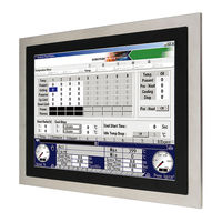
4715”/ 17”Fanless Panel PC Powered by Intel Atom, E3845, Celeron J1900 CPU Processor With DVI-I, 3COM, 4USB & 2LAN
Brand:
protech
| Category:
Touch Panel
| Size: 10 MB
Table of Contents
Table of Contents
4
Revision History
10
1 Introduction
11
About this Manual
12
2 Getting Started
13
Package List
14
System Diagrams
15
System Specifications
21
Safety Precautions
23
3 System Configuration
24
External I/O Ports Diagrams
25
Rear I/O Ports Diagram (DC IN: 9 ~ 36V)
25
Rear I/O Ports Diagram (DC IN: 12V)
25
Jumper & Connector Quick Reference Table
26
Component Locations
27
Top View and Jumper Settings of SP-7145/7147
27
Setting Jumpers
29
Setting Main Board Connectors and Jumpers
31
Lvds Power Selection
31
Backlight Inverter Pwm Voltage Selection
32
Power-On Mode Selection
33
Backlight Enable Selection
34
Vga/DVI Selection
35
Lvds Resolution Selection
36
Com3 Pin9 Definition Selection Guide
37
Com4 Voltage Selection
38
Audio Port
39
Battery Wafer
40
COM2 and COM3 PORTS
40
Com4 Connector
41
Com5 Connector
42
Com6 Connector
42
DVI-I & Com Port
43
Fan Connector
44
DC 12V Connector
44
DIO WAFER (Optional)
45
Front Connector
45
Inverter Wafer
46
Kb/Ms Port
47
Lan & Usb2.0 Port
48
Lan& Usb2.0/3.0 Port
49
Lvds Connector
50
Sata Connector
51
Usb Connector
52
Mini Pcie Connector
53
Pcie Bus
54
Lpc Connector
55
Clear Cmos Data Selection
56
Daughter Board Br-6062 Jumper Quick Reference
57
Table
57
BR-6062 Top View
57
Setting Daughter Board Br-6062 Jumpers
58
3.8.1 Rs-485 Auto Flow Control for Jcom1_1 & Jcom1
58
Rs-232/422/485 Selection for Jcom1_1 & Jcom1
59
3.8.3 Rs-485 Auto Flow Control for Jcom2_1
60
Rs-232/422/485 Selection for Jcom2_1
61
Daughter Board Sr-6100 Connector & Jumper
62
Daughter Board Sr-6100 Component Locations
62
SR-6100 Top View
62
Setting Daughter Board Sr-6100 Connectors
63
Jumpers
63
VIN Connector (+9V~+36V)
63
VOUT Connector (+12V)
63
Run Control Input Selection
64
Pulse Skipping Mode Selection
65
Continuous Mode Selection
65
4 Software Utilities
66
Installing Intel ® Chipset Software Installation Utility
66
Introduction
67
Intel ® Chipset Software Installation Utility
70
Intel ® Trusted Execution Engine Installation Utility
71
Installing Graphics Driver Utility
72
Installing LAN Driver Utility
73
Intel® USB 3.0 Extensible Host Controller Utility
74
Installing Sound Driver Utility
75
Installing Resistive Touch Driver Utility
75
Installing Projected Capacitive Touch Driver Utility
76
5 Bios Setup
77
Introduction
78
Accessing Setup Utility
79
Figure 5-2. POST Screen with AMI Logo
80
Main
83
Advanced
85
Advanced - Trusted Computing (Baytrail-I Only)
86
Advanced - ACPI Settings
87
Advanced - F81866 Super IO Configuration
88
Advanced - Hardware Monitor
95
Advanced - F81866 Watchdog Configuration
97
Advanced - CPU Configuration
98
Advanced - IDE Configuration
101
OS Selection (Baytrail-D Only)
102
Advanced - CSM Configuration
103
Advanced - USB Configuration
105
Chipset
107
Chipset - North Bridge
108
Chipset - South Bridge
112
Security
118
Boot
120
Save & Exit
123
Appendix A System Diagrams
125
SP-7145 System Exploded Diagram
126
SP-7145 Touch Panel & LCD Display Exploded Diagram
127
SP-7145 Touch Panel & LCD Display Exploded Diagram
129
SP-7145 Touch Panel & LCD Display Exploded Diagram
131
SP-7145 Touch Panel & LCD Display Exploded Diagram
133
SP-7145 Box PC Exploded Diagram
135
SP-7145 Box PC Exploded Diagram
139
SP-7145 Box PC Exploded Diagram
141
SP-7145 HDD Tray Exploded Diagram
143
SP-7145 Panel Mount Exploded Diagram
144
SP-7147 System Exploded Diagram
145
SP-7147 Touch Panel & LCD Display Exploded Diagram
146
SP-7147 Touch Panel & LCD Display Exploded Diagram
148
SP-7147 Box PC Exploded Diagram
150
SP-7147 Box PC Exploded Diagram
154
SP-7147 Box PC Exploded Diagram
156
SP-7147 HDD Tray Exploded Diagram
158
SP-7147 Panel Mount Exploded Diagram
159
Appendix B Technical Summary
160
System Block Diagram
161
Interrupt Map
162
I/O Map
166
Memory Map
170
Configuring Watchdog Timer
172
Flash BIOS Update
175
Advertisement
Advertisement
Related Products
protech SP-7625
protech SP-7627
protech SP-7629
protech SP-7755
protech SP-7145
protech SP-7165
protech SP-7167 M1
protech SP-7117
protech SP-7256
protech SP-6155
protech Categories
Toy
Touch terminals
Computer Hardware
Touch Panel
Desktop
More protech Manuals
Login
Sign In
OR
Sign in with Facebook
Sign in with Google
Upload manual
Upload from disk
Upload from URL