Sign In
Upload
Manuals
Brands
protech Manuals
Touch Panel
SP-7165
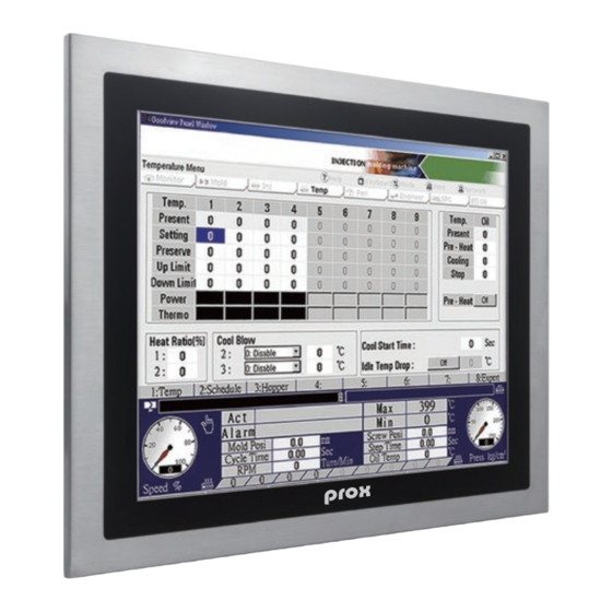
protech SP-7165 Touchscreen Panel PC Manuals
Manuals and User Guides for protech SP-7165 Touchscreen Panel PC. We have
1
protech SP-7165 Touchscreen Panel PC manual available for free PDF download: User Manual
protech SP-7165 User Manual (180 pages)
15 inch/ 17 inch Fanless Panel PC Powered by Intel CoreTM i7/i5/i3 / Pentium / Celeron CPU Processor
Brand:
protech
| Category:
Touch Panel
| Size: 4 MB
Table of Contents
Table of Contents
4
Revision History
10
1 Introduction
11
About this Manual
12
2 Getting Started
13
Package List
14
System Overview
15
System Specifications
21
Safety Precautions
23
3 System Configuration
24
External I/O Ports Diagram
25
SP-7165/SP-7167 Bottom I/O Ports Diagram
25
Jumper & Connector Quick Reference Table
26
Component Locations of System Main Board
28
Top View and Jumper Settings of SB-8400
28
Bottom View of SB-8400
30
How to Set Jumpers
31
Function Buttons and I/O Ports
33
Power Button
33
DC in Port (for SP-7165/SP-7167Rx-X0X)
33
DC in 3 Pins Terminal Block (for SP-7165/SP-7167Rx-X1X)
34
Setting Connectors and Jumpers
35
COM Port
35
COM1 Pin9 and COM2 PIN18 Definition Selection Guide3-26
37
LAN1, LAN2 Ports
38
X 1 USB 3.0 Connectors
40
SP-7167Rx-X1X) (Optional)
41
Digital Input/Output Connector
41
SP-7167Rx-X0X) (Optional)
42
DVI-I Port
43
HD Audio Connector
44
Mini PCI Express Slots
45
Serial ATA (SATA) 3.0 Connectors
47
SATA Power Connectors
48
Power Input Connector
49
DC Power Input Connector
49
LVDS Connector
50
LVDS Inverter Connector
50
PCI Express Slot (X4)
51
Control Signal Connector
52
I2C Wafer (Optional)
53
Power Button Connectors
53
Panel Power LED Connector
54
Panel HDD LED Connector
54
Low Pin Count (LPC) Connector
55
Compactflash Card Connector
56
SIM Card Slot
57
Hardware Power Failure Selection
57
Cfast Voltage Control Selection
58
LVDS Resolution Selection
59
LVDS Voltage Selection
62
Flash Descriptor Override Selection
62
VCCIO Voltage Selection
63
BIOS Recovery Mode Selection
63
Clear CMOS Data Selection
64
Touch Control Board Sr-6145 Connector Quick
65
Reference Table
65
Touch Control Board Sr-6145 Component
65
Locations
65
Touch Control Board SR-6145 Top View
65
Setting Touch Control Board Sr-6145 Connectors
66
And Jumpers
66
Control Signal Connector
66
LVDS Panel Signal Connector (Connected to Motherboard)
67
LVDS Panel Signal Connector (Connected to LCD Panel)
68
15" Panel LED Backlight Control Connector
69
Touch Panel Connector
69
LED1 Connector
70
Touch Panel up Signal Setting
71
Touch Panel Low Signal Setting
72
4 Software Utilities
73
Introduction
74
Installing Intel Chipset Software Installation Utility
76
Introduction
76
Intel ® Chipset Software Installation Utility
76
Intel ® Management Engine Components Installer Installation
77
Intel ® USB 3.0 Extensible Host Controller Utility
79
Installing Intel RST Driver Utility (Only for Q170, Optional)
80
Intel ® Rapidstorage Technology Option ROM
80
Installing Graphics Driver Utility
82
Installing LAN Driver Utility
83
Installing Sound Driver Utility
84
Installing Touch Driver Utility
84
Microsoft Hotfix Kb3211320 and Kb3213986 Driver Installation
85
5 Bios Setup
86
Introduction
87
Accessing Setup Utility
88
Main
91
Advanced
93
Advanced - CPU Configuration
94
Advanced - PCH-FW Configuration
96
Advanced - Trusted Computing
97
Advanced - ACPI Settings
98
Advanced - SATA Configuration
99
Advanced - Hardware Monitor
100
Advanced - F81866 Watchdog Configuration
101
Advanced - F81866 Super IO Configuration
102
Advanced - Network Stack Configuration
108
Advanced - USB Configuration
110
Chipset
111
Chipset - System Agent (SA) Configuration
112
Chipset - PCH-IO Configuration
117
Security
123
Boot
125
Boot - Network Device BBS Priorities
127
Boot - Hard Drive BBS Priorities
128
Boot - CSM Configuration
129
Save & Exit
131
Appendix A System Diagrams
133
SP-7165 Equipped Module PC Exploded Diagram
134
SP-7167 Equipped Module PC Exploded Diagram
135
SP-7165 LCD Display Exploded Diagram (5-Wire Resistive Touch Screen)
136
SP-7165 LCD Display Exploded Diagram (Projected Touch Screen
138
SP-7167 LCD Display Exploded Diagram (5-Wire Resistive Touch Screen)
140
SP-7167 LCD Display Exploded Diagram (Projected Touch Screen
142
SP-7165/SP-7167 Module PC Exploded Diagram
144
Diagram
146
SP-7165 Panel Mount Exploded Diagrams
148
SP-7167 Panel Mount Exploded Diagrams
149
Appendix B Technical Summary
150
System Block Diagram
151
Interrupt Map
152
I/O Map
169
Memory Map
172
Advertisement
Advertisement
Related Products
protech SP-7625
protech SP-7627
protech SP-7629
protech SP-7755
protech SP-7145
protech SP-7147
protech SP-7167 M1
protech SP-7117
protech SP-7256
protech SP-6150
protech Categories
Toy
Touch terminals
Computer Hardware
Touch Panel
Desktop
More protech Manuals
Login
Sign In
OR
Sign in with Facebook
Sign in with Google
Upload manual
Upload from disk
Upload from URL