Sign In
Upload
Manuals
Brands
PRECISION DIGITAL Manuals
Controller
ProVu PD6310
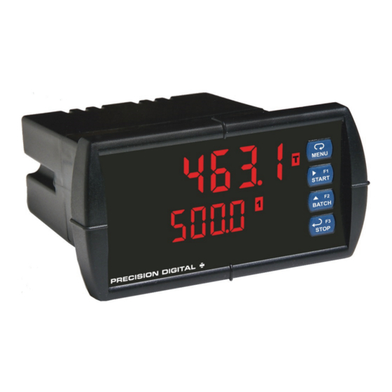
PRECISION DIGITAL ProVu PD6310 Manuals
Manuals and User Guides for PRECISION DIGITAL ProVu PD6310. We have
2
PRECISION DIGITAL ProVu PD6310 manuals available for free PDF download: Instruction Manual
PRECISION DIGITAL ProVu PD6310 Instruction Manual (104 pages)
Analog Input & Pulse Input Batch Controllers
Brand:
PRECISION DIGITAL
| Category:
Controller
| Size: 1 MB
Table of Contents
Table of Contents
3
Introduction
7
Ordering Information
7
Specifications
9
General
9
PD6210 Process Input
11
PD6310 Pulse Input
11
Batch Controller Rate/Totalizer Display
12
Relays
13
Isolated 4-20 Ma Transmitter Output
14
Modbus ® RTU Serial Communications
15
PDA1044 Digital Input & Output Expansion Module
15
Compliance Information
16
Safety
16
Electromagnetic Compatibility
16
Safety Information
17
Figure 1: 1/8 DIN Panel Cutout and Mounting
18
Installation
18
Unpacking
18
Panel Mounting Instructions
18
Figure 2: Controller Dimensions - Side View
19
Figure 3: Controller Dimensions - Top View
19
Figure 4: Jumper Configuration for 12/24 VDC Power
20
Configuration for 12 or 24 VDC Power Option
20
Figure 5: Transmitter Supply Voltage Selection
21
Connectors Labeling
22
Power Connections
22
Transmitter Supply Voltage Selection (P+, P-)
21
Connections
21
Figure 7: Power Connections
22
Figure 6: Connector Labeling for Fully Loaded PD6210
22
Figure 8: Transmitters Powered by Internal Supply
23
Figure 11: Flowmeter Powered by Internal Power Supply
25
Figure 12: Flowmeter Powered by External Supply
25
Figure 13: Self-Powered Magnetic Pickup Coil Flowmeter
25
Modbus RTU Serial Communications
26
Figure 14: Relay Connections
27
Figure 15: AC and DC Loads Protection
27
Relay Connections
27
Switching Inductive Loads
27
4-20 Ma Output Connections
28
Analog Output Transmitter Power Supply
28
Figure 16: Low Voltage DC Loads Protection
28
Figure 17: 4-20 Ma Output Connections
28
External Relay & Digital I/O Connections
29
Figure 18: Expansion Modules & DIN Rail Mounting Kit
29
Figure 19: External Relays Module Connections
29
Interlock Relay Feature
30
Figure 9: Transmitter Powered by Ext. Supply or Self-Powered
23
PD6210 Signal Connections
23
Figure 10: Voltage Input Connections
24
PD6310 Signal Connections
25
Figure 20: Digital I/O Module Connections
30
Figure 21: Interlock Connection
30
Basic Operation and Programming
31
Front Panel Buttons and Status LED Indicators
32
Controller Operation
33
Batch Control Operation Example
34
Model PD6210 & PD6310 Batch Controllers Instruction Manual
42
Control Menu (Contrl)
42
Setting Numeric Values
42
Reset Menu (Reset)
42
Setting up the Batch Controller (Setup)
43
Scaling and Calibration
44
Setting the Input Signal (Input)
45
Setting the Totalizer and Batching Features (Total)
45
Setting the Decimal Point (Dec Pt)
45
Programming the Rate/Totalizer (Prog)
46
Scaling the Controller (SCALE)
47
Time Base, Total Conversion Factor & Total Reset
48
Batch Start Mode (Mode)
48
Calibrating the Controller with External Source (Cal)
49
Setting the Display Parameter & Intensity (Dsplay)
50
Display Setup Menu
51
Character Set for Engineering Units Display (D Unit)
52
Setting the Relay Operation (Relay)
53
Relay Assignment (Assign)
54
Setting the Relay Action
55
Setting Batch Control Relays
55
Programming Alarm Set and Reset Points
56
Setting Fail-Safe Operation
56
Programming Time Delay
56
Relay Action for Loss of 4-20 Ma Input (Loop Break)
56
Relay Operation Details
57
Overview
57
Relays Initialization
57
Fail-Safe Operation
57
Front Panel Leds
58
Automatic Reset (Auto)
58
Pump Alternation Control
58
Setting up the Interlock Relay (Force On) Feature
59
Sample Relay Operation
60
Relay and Alarm Operation Diagrams
60
High Alarm Operation (Set > Reset)
60
Low Alarm Operation (Set < Reset)
60
High Alarm with Fail-Safe Operation (Set > Reset)
61
Low Alarm with Fail-Safe Operation (Set < Reset)
61
Rate Relay Sampling Operation
61
Total Relay Sampling Operation
62
Signal Loss or Loop Break Relay Operation
63
Time Delay Operation
64
Scaling the 4-20 Ma Analog Output (Aout)
65
Setting up the Password (Pass)
66
Protecting or Locking the Controller
66
Model PD6210 & PD6310 Batch Controllers Instruction Manual
67
Grand Total Reset Password & Non-Resettable Total
67
Making Changes to a Password Protected Controller
67
Disabling Password Protection
68
Advanced Operation and Programming
69
Advanced Features Menu & Display Messages
70
Programmable Function Keys User Menu (User)
73
Multi-Point Calibration & Scaling
74
Meterview ® Pro Software
74
Noise Filter Bypass (Bypass)
76
Modbus RTU Serial Communications (Serial)
77
Select Menu (Select)
78
Signal Conditioning Selection (Functn)
78
Analog Output Programming (Aoutpr)
80
PD6210 Only: Internal Source Calibration (ICAL)
81
Controller Copy Function (Copy)
84
Figure 22: Controller Copy Connection
84
Troubleshooting
86
Diagnostics Menu (Diag)
86
Determining Software Version
86
Reset Controller to Factory Defaults
87
Factory Defaults & User Settings
88
Troubleshooting Tips
92
Alphabetical List of Display Functions & Messages
93
Figure 23: 1/8 DIN Panel Cutout Template
101
Advertisement
PRECISION DIGITAL ProVu PD6310 Instruction Manual (52 pages)
Pulse Input Batch Controller
Brand:
PRECISION DIGITAL
| Category:
Controller
| Size: 3 MB
Table of Contents
Table of Contents
3
Table of Figures
4
Introduction
4
Ordering Information
5
Specifications
6
General
6
Pulse Input
6
Batch Controller Rate/Totalizer Display
7
Relays
7
Isolated 4-20 Ma Transmitter Output
8
Modbus ® RTU Serial Communications
8
PDA1044 Digital Input & Output Expansion Module
8
Meterview Pro
8
Compliance Information
9
Safety
9
Electromagnetic Compatibility
9
Figure 1: 1/8 DIN Panel Mounting
10
Mounting Dimensions
11
Safety Information
10
Installation
10
Unpacking
10
Panel Mounting Instructions
10
Figure 2: Controller Dimensions - Side View
11
Figure 3: Controller Dimensions - Top View
11
Figure 4: Transmitter Supply Voltage Selection
11
Transmitter Supply Voltage Selection (P+, P-)
11
Figure 6: Power Connections
12
Figure 5: Connector Labeling for Fully Loaded
12
Modbus RTU Serial Communications
13
Pulse Signal Connections
13
Relay Connections
13
Connections
12
Connectors Labeling
12
Power Connections
12
Figure 11: PNP Sensor Powered by Internal Supply
13
Figure 12: Switch Input Connections
13
Figure 10: NPN Open Collector Input
13
Figure 13: Relay Connections
13
Figure 15: Low Voltage DC Loads Protection
14
Figure 14: AC and DC Loads Protection
14
Figure 16: F4 Digital Input Connections
14
4-20 Ma Output Connections
15
Analog Output Transmitter Power Supply
15
External Relay & Digital I/O Connections
15
Figure 17: 4-20 Ma Output Connections
15
Figure 20: Digital I/O Module Connections
15
Figure 19: External Relays Module Connections
15
Figure 18: Expansion Modules & DIN Rail Mounting Kit
15
Interlock Relay Feature
16
Figure 9: Self-Powered Magnetic Pickup Coil Flowmeter
13
Figure 8: Flowmeter Powered by External Supply
13
Figure 7: Flowmeter Powered by Internal Power Supply
13
F4 Digital Input Connections
14
Switching Inductive Loads
14
Figure 21: Interlock Connection
16
Basic Operation and Programming
17
Front Panel Buttons and Status LED Indicators
17
Controller Operation
18
Batch Control Operation Example
19
Meterview ® Pro Software
21
Meterview Pro Installation
21
Display Functions and Messages
22
Setting Numeric Values
24
Setting up the Batch Controller (Setup)
25
Scaling and Calibration
26
Setting the Input Signal (Input)
26
Setting the Totalizer and Batching Features (Total)
26
Setting the Input Units or Custom Tags (Units)
26
Setting the Decimal Point (Dec Pt)
27
Programming the Batch Controller (Prog)
27
Input Calibration Method (Incal)
28
K-Factor Calibration (Factor)
28
Scaling the Controller (SCALE)
29
Reset
29
Batch Start Mode (Mode)
30
Calibrating the Controller with External Source (Cal)
30
Setting the Display Parameter & Intensity (Dsplay)
31
Setting the Relay Operation (Relay)
32
Relay Assignment (Assign)
33
Setting the Relay Action
33
Setting Batch Control Relays
33
Programming Alarm Set and Reset Points
34
Setting Fail-Safe Operation
34
Programming Time Delay
34
Relay Operation Details
35
Overview
35
Relays Initialization
35
Fail-Safe Operation
35
Front Panel Leds
35
Automatic Reset (Auto)
36
Pump Alternation Control
36
Setting up the Interlock Relay (Force On) Feature
36
Sample Relay Operation
37
Relay and Alarm Operation Diagrams
37
High Alarm Operation (Set > Reset)
37
Low Alarm Operation (Set < Reset)
37
High Alarm with Fail-Safe Operation (Set > Reset)
37
Low Alarm with Fail-Safe Operation (Set < Reset)
37
Rate Relay Sampling Operation
38
Total Relay Sampling Operation
38
Time Delay Operation
39
Scaling the 4-20 Ma Analog Output (Aout)
39
Reset Menu (Reset)
40
Control Menu (Contrl)
40
Setting up the Password (Pass)
40
Protecting or Locking the Controller
40
Grand Total Reset Password & Non-Resettable Total
41
Making Changes to a Password Protected Controller
41
Disabling Password Protection
41
Advanced Operation and Programming
42
Advanced Features Menu & Display Messages
42
Function Keys Operation
44
F4 Operation
44
Multi-Point Calibration & Scaling
44
Maximum/Minimum Readings
44
Noise Filter (Filter)
45
Noise Filter Bypass (Bypass)
45
Rounding Feature (Round)
45
Modbus RTU Serial Communications (Serial)
45
Select Menu (Select)
46
Signal Conditioning Selection (Functn)
46
Low-Flow Cutoff (Cutoff)
46
Total and Grand Total Count Direction (Count)
46
Analog Output Programming (Aoutpr)
47
Programmable Function Keys User Menu (User)
47
Troubleshooting
49
Diagnostics Menu (Diag)
49
Determining Software Version
49
Reset Controller to Factory Defaults
49
Factory Defaults & User Settings
50
Troubleshooting Tips
52
Advertisement
Related Products
PRECISION DIGITAL PD6310-WM
PRECISION DIGITAL PD6310-6R2
PRECISION DIGITAL PD6310-7R2
PRECISION DIGITAL PD6310-6R4
PRECISION DIGITAL PD6310-7R4
PRECISION DIGITAL PD6310-6R5
PRECISION DIGITAL PD6310-7R5
PRECISION DIGITAL PD6310-6R7
PRECISION DIGITAL PD6310-7R7
PRECISION DIGITAL PD6310-6H2
PRECISION DIGITAL Categories
Measuring Instruments
Controller
Monitor
Scanner
Network Hardware
More PRECISION DIGITAL Manuals
Login
Sign In
OR
Sign in with Facebook
Sign in with Google
Upload manual
Upload from disk
Upload from URL