Sign In
Upload
Manuals
Brands
PRECISION DIGITAL Manuals
Measuring Instruments
PD6060
PRECISION DIGITAL PD6060 Manuals
Manuals and User Guides for PRECISION DIGITAL PD6060. We have
3
PRECISION DIGITAL PD6060 manuals available for free PDF download: Instruction Manual
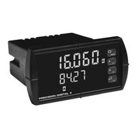
PRECISION DIGITAL PD6060 Instruction Manual (104 pages)
ProVu Series Dual-Input Process Meter
Brand:
PRECISION DIGITAL
| Category:
Measuring Instruments
| Size: 1 MB
Table of Contents
Table of Contents
3
Introduction
6
Ordering Information
7
Specifications
8
General
8
Dual Process Input
10
Relays
11
Isolated 4-20 Ma Transmitter Output
12
Modbus® RTU Serial Communications
13
PDA1044 Digital Input & Output Expansion Module
13
Ro Vu
13
Compliance Information
14
Safety
14
Electromagnetic Compatibility
14
Safety Information
15
Installation
16
Unpacking
16
Panel Mounting Instructions
16
Figure 1. 1/8 DIN Panel Cutout Dimensions
16
Configuration for 12 or 24 VDC Power Option
17
Figure 2. Panel Mounting Details
17
Figure 3. Jumper Configuration for 12/24 VDC Power
17
Transmitter Supply Voltage Selection (P+, P-)
18
Connections
18
Figure 4. Transmitter Supply Voltage Selection
18
Connectors Labeling
19
Figure 5. Connector Labeling for Fully Loaded PD6060
19
Figure 6. Power Connections
19
Power Connections
19
Figure 7. Transmitters Powered by Internal Supply
20
Figure 8. Transmitter Powered by Ext. Supply or Self-Powered
20
Signal Connections
20
Figure 10. Relay Connections
21
Figure 9. Voltage Input Connections
21
Modbus RTU Serial Communications
21
Relay Connections
21
Figure 11. AC and DC Loads Protection
22
Figure 12. Low Voltage DC Loads Protection
22
Switching Inductive Loads
22
4-20 Ma Output Connections
23
Analog Output Transmitter Power Supply
23
F4 Digital Input Connections
23
Figure 13. F4 Digital Input Connections
23
Figure 14. 4-20 Ma Output Connections
23
External Relays & Digital I/O Connections
24
Figure 15. Expansion Modules & DIN Rail Mounting Kit
24
Figure 16. External Relays Module Connections
24
Figure 17. Digital I/O Module Connections
25
Figure 18. Interlock Connections
25
Interlock Relay Feature
25
Setup and Programming
26
Front Panel Buttons and Status LED Indicators
27
Display Functions & Messages
28
Main Menu
33
Setting Numeric Values
34
Reset Menu (Reset)
34
Control Menu (Contrl)
34
Setting up the Meter (Setup)
35
Setting the Input Signal (Input)
36
Setting the Decimal Point (Dec Pt)
36
Programming the Meter (Prog)
37
Multi-Point Calibration & Scaling
38
Meterview ® Pro Software
38
Scaling the Meter Without a Signal Source
38
Scaling the Meter for Channel a (Scal A)
39
Scaling the Meter for Channel B (Scal B)
39
Calibrating the Meter with External Source
40
Calibrating the Meter for Channel a (CAL-A)
41
Calibrating the Meter for Channel B (CAL-B)
41
Setting the Display Parameter & Intensity (Dsplay)
42
Display Setup Menu
43
Character Set for Engineering Units Display (D Unit)
44
Setting the Relay Operation (Relay)
45
Setting the Relay Assignment (Assign)
46
Setting the Relay Action
47
Programming Set and Reset Points
48
Setting Fail-Safe Operation
48
Programming Time Delay
48
Relay Action for Loss of 4-20 Ma Input (Loop Break)
48
Relay and Alarm Operation Diagrams
49
High Alarm Operation (Set > Reset)
49
Low Alarm Operation (Set < Reset)
50
High Alarm with Fail-Safe Operation (Set > Reset)
51
Low Alarm with Fail-Safe Operation (Set < Reset)
52
Pump Alternation Control Operation
53
Relay Sampling Operation
54
Signal Loss or Loop Break Relay Operation
55
Time Delay Operation
56
Relay Operation Details
57
Overview
57
Relays Auto Initialization
57
Fail-Safe Operation
57
Front Panel Leds
58
Latching and Non-Latching Relay Operation
58
Non-Latching Relay (Auto)
59
Non-Latching Relay (A-Man)
59
Latching Relay (Latch)
59
Latching Relay (Lt-Clr)
60
Acknowledging Relays
60
Figure 19. Acknowledge Relays W/Function Key or Digital Input
60
Pump Alternation Control Applications (Altern)
61
Setting up the Interlock Relay (Force On) Feature
62
Scaling the 4-20 Ma Analog Output (Aout)
63
Setting up the Password (Pass)
64
Protecting or Locking the Meter
64
Making Changes to a Password Protected Meter
65
Disabling Password Protection
65
Advanced Features Menu
66
Advanced Features Menu & Display Messages
67
Noise Filter (Filter)
70
Noise Filter Bypass (Bypass)
71
Modbus RTU Serial Communications (Serial)
72
Select Menu (Select)
72
Signal Input Conditioning (Functn)
74
Low-Flow Cutoff (Cutoff)
76
Analog Output Programming (Aoutpr)
76
Programmable Function Keys User Menu (User)
78
Tare (Tare A, Tare B)
80
Internal Calibration (ICAL)
80
Meter Copy Function (Copy)
83
Figure 20. Meter Copy Connection
83
Meter Operation
85
Front Panel Buttons Operation
85
Function Keys Operation
85
F4 Operation
86
Maximum/Minimum Readings
86
Troubleshooting
87
Diagnostics Menu (Diag)
87
Determining Software Version
87
Reset Meter to Factory Defaults
88
Factory Defaults & User Settings
89
Troubleshooting Tips
93
Alphabetical List of Display Functions & Messages
94
Figure 21. Meter Dimensions - Side View
99
Figure 22. Meter Dimensions - Top View
99
Mounting Dimensions
99
Model PD6060 Dual-Input Process Meter Instruction Manual
100
Figure 23. 1/8 DIN Panel Cutout Template
101
Advertisement
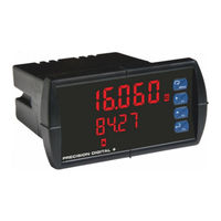
PRECISION DIGITAL PD6060 Instruction Manual (47 pages)
Dual Analog Input Process Meter
Brand:
PRECISION DIGITAL
| Category:
Measuring Instruments
| Size: 3 MB
Table of Contents
Table of Contents
3
Introduction
6
Ordering Information
6
Specifications
7
General
7
Dual Process Input
8
Relays
9
Isolated 4-20 Ma Transmitter Output
9
USB Connection
10
On-Board Digital Input (F4)
10
Modbus ® RTU Serial Communications
10
Meterview Pro
10
Compliance Information
11
Safety
11
Electromagnetic Compatibility
11
Safety Information
11
Installation
11
Unpacking
11
Panel Mounting Instructions
12
Mounting Dimensions
12
Figure 1. 1/8 DIN Panel Cutout Dimensions
12
Figure 2. Panel Mounting Details
12
Figure 3. Meter Dimensions - Side View
12
Figure 4. Meter Dimensions - Top View
12
Installation Overview
13
Meterview Pro Software
13
Meterview Pro Installation
13
Transmitter Supply Voltage Selection (P+, P-)
14
Connections
14
Connectors Labeling
14
Figure 5. Transmitter Supply Voltage Selection
14
Figure 6. PD6060-##0 Connectors Label
14
Figure 7. PD6060-##2 Connectors Label
14
Figure 8. PD6060-##3 Connectors Label
14
Figure 9. PD6060-##4 Connectors Label
14
Figure 10. PD6060-##5 Connectors Label
14
Figure 11. PD6060-##7 Connectors Label
14
Power Connections
15
Signal Connections
15
Modbus RTU Serial Communications
15
Relay Connections
15
Figure 12. Power Connections
15
Figure 13. Transmitters Powered by Internal Supply
15
Figure 14. Transmitter Powered by Ext. Supply or Self-Powered
15
Figure 15. Voltage Input Connections
15
Figure 16. Relay Connections
15
Switching Inductive Loads
16
F4 Digital Input Connections
16
4-20 Ma Output Connections
16
Analog Output Power Supply
16
Figure 17. AC and DC Loads Protection
16
Figure 18. Low Voltage DC Loads Protection
16
Figure 19. F4 Digital Input Connections
16
Figure 20. 4-20 Ma Output Connections
16
Figure 21. Analog Output Supply Powering Other Devices
16
External Relay, Analog Output, & Digital I/O Connections
17
Interlock Relay Feature
17
Figure 22. Expansion Module & DIN Rail Mounting Kit
17
Figure 23. External Relays Module Connections
17
Figure 24. Digital I/O Module Connections
17
Figure 25. Dual 4-20 Ma Output Module Connections
17
Figure 26. Interlock Connections
17
Setup and Programming
18
Overview
18
Front Panel Buttons and Status LED Indicators
18
Display Functions & Messages
19
Main Menu
21
Setting Numeric Values
21
Setting up the Meter (Setup)
21
Setting the Input Signal (Input)
22
Setting the Display Units or Custom Tags (Units)
22
Setting the Decimal Point (Dec Pt)
23
Programming the Meter (Prog)
23
Setting the Display Parameter & Intensity (Dsplay)
25
Display Intensity (D-Inty)
25
Setting the Relay Operation (Relay)
26
Setting the Relay Assignment (Assign)
26
Setting the Relay Action
26
Programming Set and Reset Points
27
Setting Fail-Safe Operation
27
Programming Time Delay
27
Relay Action for Loss of 4-20 Ma Input (Loop Break)
27
Relay and Alarm Operation Diagrams
27
High Alarm Operation (Set > Reset)
27
Low Alarm Operation (Set < Reset)
28
High Alarm with Fail-Safe Operation (Set > Reset)
28
Low Alarm with Fail-Safe Operation (Set < Reset)
28
Time Delay Operation
28
Pump Alternation Control Operation
29
Relay Sampling Operation
29
Relay Operation Details
30
Overview
30
Relays Auto Initialization
30
Fail-Safe Operation
30
Front Panel Leds
30
Latching and Non-Latching Relay Operation
30
Non-Latching Relay (Auto)
31
Non-Latching Relay with Manual Reset (A-Nman)
31
Latching Relay (Latch)
31
Latching Relay with Clear (Lt-Clr)
31
Acknowledging Relays
31
Pump Alternation Control Applications (Altern)
32
Setting up the Interlock Relay (Force On) Feature
32
Scaling the 4-20 Ma Analog Output (Aout)
33
Reset Menu (Reset)
33
Manual Control Menu (Contrl)
33
Setting up the Password (Pass)
34
Protecting or Locking the Meter
34
Making Changes to a Password Protected Meter
34
Disabling Password Protection
34
Advanced Features Menu
35
Advanced Features Menu & Display Messages
35
Noise Filter (Filter)
36
Noise Filter Bypass (Bypass)
36
Rounding Feature (Round)
37
Modbus RTU Serial Communications (Serial)
37
Select Menu (Select)
37
Input Signal Conditioning (Functn)
37
Multi-Point Linearization (Linear)
38
Math Function (Nmath)
39
Math Constants (Const)
39
Low-Flow Cutoff (Cutoff)
39
Analog Output Programming (Aoutpr)
39
Programmable Function Keys User Menu (User)
40
Tare (Tare A, Tare B)
41
Internal Calibration (ICAL)
41
Meter Operation
42
Front Panel Buttons Operation
42
Function Keys Operation
42
F4 Operation
42
Maximum/Minimum Readings
42
Troubleshooting
43
Diagnostics Menu (Diag)
43
Determining Software Version
43
Reset Meter to Factory Defaults
43
Factory Defaults & User Settings
43
Troubleshooting Tips
45
EU Declaration of Conformity
46
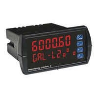
PRECISION DIGITAL PD6060 Instruction Manual (56 pages)
Dual-Input Process Meter
Brand:
PRECISION DIGITAL
| Category:
Measuring Instruments
| Size: 3 MB
Table of Contents
Table of Contents
3
Table of Figures
4
Introduction
4
Ordering Information
5
Specifications
6
General
6
Dual Process Input
7
Relays
7
Isolated 4-20 Ma Transmitter Output
8
Modbus® RTU Serial Communications
8
Meterview Pro
8
Compliance Information
9
Safety
9
Electromagnetic Compatibility
9
Figure 2. Panel Mounting Details
10
Figure 1. 1/8 DIN Panel Cutout Dimensions
10
Mounting Dimensions
11
Safety Information
10
Installation
10
Unpacking
10
Panel Mounting Instructions
10
Figure 3. Meter Dimensions - Side View
11
Figure 4. Meter Dimensions - Top View
11
Figure 5. Transmitter Supply Voltage Selection
11
Transmitter Supply Voltage Selection (P+, P-)
11
Figure 7. Power Connections
12
Figure 6. Connector Labeling for Fully Loaded
12
Signal Connections
13
Connections
12
Connectors Labeling
12
Power Connections
12
Figure 10. Voltage Input Connections
13
Figure 8. Transmitters Powered by Internal Supply
13
Figure 9. Transmitter Powered by Ext. Supply or Self
13
Figure 11. Relay Connections
14
Figure 12. AC and DC Loads Protection
14
Figure 13. Low Voltage DC Loads Protection
14
4-20 Ma Output Connections
15
Analog Output Transmitter Power Supply
15
F4 Digital Input Connections
15
Figure 15. 4-20 Ma Output Connections
15
External Relay, Analog Output, & Digital I/O Connections
16
Interlock Relay Feature
16
Modbus RTU Serial Communications
14
Relay Connections
14
Switching Inductive Loads
14
Figure 14. F4 Digital Input Connections
15
Figure 16. Interlock Connections
16
Setup and Programming
17
Front Panel Buttons and Status LED Indicators
17
Meterview ® Pro Software
18
Meterview Pro Installation
18
Display Functions & Messages
19
Main Menu
21
Setting Numeric Values
21
Setting up the Meter (Setup)
22
Setting the Input Signal (Input)
22
Setting the Decimal Point (Dec Pt)
23
Programming the Meter (Prog)
23
Setting the Display Parameter & Intensity (Dsplay)
26
Setting the Input Units or Custom Tags (Units)
27
Setting the Relay Operation (Relay)
28
Setting the Relay Assignment (Assign)
28
Setting the Relay Action
29
Programming Set and Reset Points
29
Setting Fail-Safe Operation
29
Programming Time Delay
29
Relay Action for Loss of 4-20 Ma Input (Loop Break)
29
Relay and Alarm Operation Diagrams
30
High Alarm Operation (Set > Reset)
30
Low Alarm Operation (Set < Reset)
30
High Alarm with Fail-Safe Operation (Set > Reset)
30
Low Alarm with Fail-Safe Operation (Set < Reset)
30
Pump Alternation Control Operation
31
Relay Sampling Operation
31
Signal Loss or Loop Break Relay Operation
32
Time Delay Operation
32
Relay Operation Details
33
Fail-Safe Operation
33
Overview
33
Relays Auto Initialization
33
Front Panel Leds
34
Latching and Non-Latching Relay Operation
34
Latching Relay (Latch)
34
Non-Latching Relay (A-Man)
34
Non-Latching Relay (Auto)
34
Acknowledging Relays
35
Figure 17. Acknowledge Relays W/Function Key or Digital Input
35
Latching Relay (Lt-Clr)
35
Pump Alternation Control Applications (Altern)
36
Setting up the Interlock Relay (Force On) Feature
37
Scaling the 4-20 Ma Analog Output (Aout)
38
Reset Menu (Reset)
38
Control Menu (Contrl)
38
Setting up the Password (Pass)
39
Protecting or Locking the Meter
39
Making Changes to a Password Protected Meter
39
Disabling Password Protection
39
Advanced Features Menu
40
Advanced Features Menu & Display Messages
40
Noise Filter (Filter)
42
Noise Filter Bypass (Bypass)
42
Rounding Feature (Round)
42
Modbus RTU Serial Communications (Serial)
42
Select Menu (Select)
43
Signal Input Conditioning (Functn)
43
Multi-Point Linearization (Linear)
44
Math Function (Math)
45
Math Constants (Const)
45
Low-Flow Cutoff (Cutoff)
45
Analog Output Programming (Aoutpr)
46
Programmable Function Keys User Menu (User)
46
Tare (Tare A, Tare B)
48
Internal Calibration (ICAL)
48
Meter Operation
50
Front Panel Buttons Operation
50
Function Keys Operation
50
F4 Operation
50
Maximum/Minimum Readings
50
Troubleshooting
51
Diagnostics Menu (Diag)
51
Determining Software Version
51
Reset Meter to Factory Defaults
51
Factory Defaults & User Settings
52
Troubleshooting Tips
54
EU Declaration of Conformity
55
Advertisement
Advertisement
Related Products
PRECISION DIGITAL PD603
PRECISION DIGITAL PD6000-6R0
PRECISION DIGITAL PD6000-6R2
PRECISION DIGITAL PD6000-6R3
PRECISION DIGITAL PD6000-6R4
PRECISION DIGITAL PD6000-7R5
PRECISION DIGITAL PD6000-6R7
PRECISION DIGITAL PD6000-7R2
PRECISION DIGITAL PROVU PD6001
PRECISION DIGITAL PROVU PD6089 Modbus
PRECISION DIGITAL Categories
Measuring Instruments
Controller
Monitor
Scanner
Network Hardware
More PRECISION DIGITAL Manuals
Login
Sign In
OR
Sign in with Facebook
Sign in with Google
Upload manual
Upload from disk
Upload from URL