Sign In
Upload
Manuals
Brands
PRECISION DIGITAL Manuals
Measuring Instruments
PD6000-6R4
User Manuals: PRECISION DIGITAL PD6000-6R4 Panel Meter
Manuals and User Guides for PRECISION DIGITAL PD6000-6R4 Panel Meter. We have
1
PRECISION DIGITAL PD6000-6R4 Panel Meter manual available for free PDF download: Instruction Manual
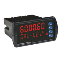
PRECISION DIGITAL PD6000-6R4 Instruction Manual (88 pages)
PD6000 series Analog Input Process Meter
Brand:
PRECISION DIGITAL
| Category:
Measuring Instruments
| Size: 1 MB
Table of Contents
Introduction
3
Ordering Information
3
Table of Contents
4
Specifications
8
General
8
Process Input
9
Relays
10
Isolated 4-20 Ma Transmitter Output
11
Serial Communications
11
PDA1044 Digital Input & Output Expansion Module
12
Compliance Information
13
Safety
13
Electromagnetic Compatibility
13
Safety Information
14
Installation
15
Unpacking
15
Panel Mounting Instructions
15
Figure 1. 1/8 DIN Panel Cutout Dimensions
15
Configuration for 12 or 24 VDC Power Option
16
Figure 2. Panel Mounting Details
16
Figure 3. Jumper Configuration for 12/24 VDC Power
16
Transmitter Supply Voltage Selection (P+, P-)
17
Connections
17
Figure 4. Transmitter Supply Voltage Selection
17
Connectors Labeling
18
Figure 5. Connector Labeling for Fully Loaded PD6000
18
Figure 6. Power Connections
18
Power Connections
18
Figure 7. Transmitters Powered by Internal Supply
19
Figure 8. Transmitter Powered by Ext. Supply or Self-Powered
19
Signal Connections
19
Figure 10. Relay Connections
20
Figure 9. Voltage Input Connections
20
Relay Connections
20
Serial Communications
20
Figure 11. AC and DC Loads Protection
21
Figure 12. Low Voltage DC Loads Protection
21
Switching Inductive Loads
21
4-20 Ma Output Connections
22
Analog Output Transmitter Power Supply
22
Figure 13. 4-20 Ma Output Connections
22
External Relays & Digital I/O Connections
23
Figure 14. Expansion Modules & DIN Rail Mounting Kit
23
Figure 15. External Relays Module Connections
23
Figure 16. Digital I/O Module Connections
23
Setup and Programming
24
Front Panel Buttons and Status LED Indicators
25
Display Functions & Messages
26
Main Menu
29
Setting Numeric Values
30
Reset Menu (Reset)
30
Control Menu (Contrl)
30
Setting up the Meter (Setup)
31
Setting the Input Signal (Input)
32
Setting the Decimal Point (Dec Pt)
32
Setting the Display Parameter & Intensity (Dsplay)
32
Programming the Meter (Prog)
35
Multi-Point Calibration & Scaling
35
Multi-Point Linearization Utility
35
Scaling the Meter (SCALE)
36
Calibrating the Meter with External Source (Cal)
38
Setting the Relay Operation (Relay)
39
Setting the Relay Action
40
Programming Set and Reset Points
41
Setting Fail-Safe Operation
41
Programming Time Delay
41
Relay Action for Loss of 4-20 Ma Input (Loop Break)
41
Relay and Alarm Operation Diagrams
42
High Alarm Operation (Set > Reset)
42
Low Alarm Operation (Set < Reset)
43
High Alarm with Fail-Safe Operation (Set > Reset)
44
Low Alarm with Fail-Safe Operation (Set < Reset)
45
Pump Alternation Control Operation
46
Relay Sampling Operation
47
Signal Loss or Loop Break Relay Operation
48
Time Delay Operation
49
Relay Operation Details
50
Overview
50
Relays Auto Initialization
50
Fail-Safe Operation
50
Front Panel Leds
51
Latching and Non-Latching Relay Operation
51
Non-Latching Relay (Auto)
52
Non-Latching Relay (A-Man)
52
Latching Relay (Latch)
52
Latching Relay (Lt-Clr)
53
Acknowledging Relays
53
Figure 17. Acknowledge Relays W/Function Key or Digital Input
53
Pump Alternation Control Applications (Altern)
54
Scaling the 4-20 Ma Analog Output (Aout)
57
Setting up the Password (Pass)
58
Protecting or Locking the Meter
58
Making Changes to a Password Protected Meter
59
Disabling Password Protection
59
Advanced Features Menu
60
Advanced Features Menu & Display Messages
61
Noise Filter (Filter)
63
Noise Filter Bypass (Bypass)
63
Serial Communications (Serial)
64
Select Menu (Select)
65
Math Function Selection (Functn)
65
Low-Flow Cutoff (Cutoff)
67
Analog Output Programming (Aoutpr)
67
Programmable Function Keys User Menu (User)
68
Internal Source Calibration (ICAL)
69
Meter Copy Function (Copy)
72
Figure 18. Meter Copy Connection
72
Meter Operation
74
Front Panel Buttons Operation
74
Function Keys Operation
74
Maximum/Minimum Readings
75
Troubleshooting
76
Diagnostics Menu (Diag)
76
Determining Software Version
76
Reset Meter to Factory Defaults
77
Factory Defaults & User Settings
78
Troubleshooting Tips
81
Alphabetical List of Display Functions & Messages
82
Mounting Dimensions
87
Figure 19. Meter Dimensions - Side View
87
Figure 20. Meter Dimensions - Top View
87
Advertisement
Advertisement
Related Products
PRECISION DIGITAL PD6000-6R0
PRECISION DIGITAL PD6000-6R2
PRECISION DIGITAL PD6000-6R3
PRECISION DIGITAL PD6000-6R5
PRECISION DIGITAL PD6000-6R7
PRECISION DIGITAL PD6000-7R0
PRECISION DIGITAL PD6000-7R3
PRECISION DIGITAL PD6000-7R4
PRECISION DIGITAL PD6000-7R5
PRECISION DIGITAL PD6000-7R7
PRECISION DIGITAL Categories
Measuring Instruments
Controller
Monitor
Scanner
Network Hardware
More PRECISION DIGITAL Manuals
Login
Sign In
OR
Sign in with Facebook
Sign in with Google
Upload manual
Upload from disk
Upload from URL