Sign In
Upload
Manuals
Brands
Power Automation Manuals
Control Unit
PA 8000 LW Series
Power Automation PA 8000 LW Series Manuals
Manuals and User Guides for Power Automation PA 8000 LW Series. We have
2
Power Automation PA 8000 LW Series manuals available for free PDF download: Installation Instructions Manual
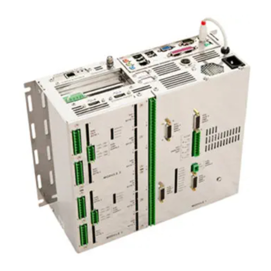
Power Automation PA 8000 LW Series Installation Instructions Manual (132 pages)
CNC control unit
Brand:
Power Automation
| Category:
Control Unit
| Size: 3 MB
Table of Contents
Table of Contents
3
1 General Information
7
Information on this Manual
7
Explanation of Symbols
7
Limitation of Liability
9
Copyright
9
Warranty Terms
9
Customer Service
10
Glossary
11
2 Safety
13
Customer's Responsibility
13
Personnel Requirements
14
Qualifications
14
Unauthorized Persons
14
Intended Use
15
Unintended Use
15
Personal Protective Gear
16
Specific Dangers
16
Safety Devices
18
Machine Safety
19
CNC Ready' Signal - Emergency Stop Interlocking
19
Power Ok' Signal
20
Conduct in a Dangerous Situation and in Case of Accidents
20
Data Safety
21
File Backup
21
System Protection
21
Environmental Protection
23
Labels
24
3 Design and Function
27
Overview
27
Brief Description
29
Module 4AXLX
30
Digital Inputs
31
Input Interfaces
31
Input Characteristics
32
Input Schematic
33
RMS Encoder Wiring Example
34
Analog Outputs
35
Output Interfaces
35
Output Characteristics
36
Output Schematic
37
Output Monitor
38
Analog Axes Wiring Example
38
RMS Power Supply
40
Module 4AXLX Leds
42
Module 2416 el
43
Digital Inputs
44
Input Interfaces
44
Input Characteristics
48
Input Schematic
49
Handwheel I/O
49
Digital Outputs
52
Output Interfaces
52
Output Characteristics
56
Output Schematic
57
Power Connection
58
Module 2416 el Leds
61
SDI Interface
62
PC Connectors
64
Safety Connector
75
Safety Connector Specification
75
Safety Connector Schematic
78
X20) PA USB Software Dongle Connector
78
PAMIO Interface (Superbus)
79
PAMIO Boxes and Modules
80
4 Technical Data
83
General Specifications
83
Connection Values
83
Operating Conditions
84
Dimension Sheet
85
Electromagnetic Compatibility
87
Installation Guidelines
88
5 Installation
91
Prerequisites and Preparations
91
General Requirements
91
Electrical Cabinet Structural Requirements
92
Cabinet Temperature
92
Mounting the Control Unit in a Cabinet
93
Installing Analog Axes
95
Analog Axes Wiring Example
96
RMS Encoder Wiring Example
97
Setting up RMS Supply Voltage Drop Compensation
98
Installing Digital I/O
100
Wiring Example for 2416EL Modules
101
Wiring for Machine Safety
102
Wiring Example for 'CNC Ready' Relay
102
Wiring Example for 'Power Ok' Relay
103
6 Transport, Packaging and Storage
105
Transport
105
Packaging
105
Storage
106
7 Maintenance
107
Safety Notes
107
Maintenance Schedule
107
Measures after Maintenance
108
8 Troubleshooting
109
Safety Notes
109
Malfunction Indicators
110
Module 4AXLX Leds
111
Module 2416 el Leds
115
Troubleshooting Chart
117
9 Service and Return Process
119
Service
119
Service Addresses
119
Spare Parts
121
Return Policy and Procedure
121
Training
124
10 Dismounting and Decommissioning
125
11 EC Declaration of Conformity
127
12 Proof of Change
129
13 Index
131
Advertisement
Power Automation PA 8000 LW Series Installation Instructions Manual (108 pages)
CNC control unit
Brand:
Power Automation
| Category:
Control Unit
| Size: 3 MB
Table of Contents
Table of Contents
3
1 General Information
7
Information on this Manual
7
Explanation of Symbols
7
Limitation of Liability
9
Copyright
9
Warranty Terms
9
Customer Service
10
Glossary
10
2 Safety
11
Customer's Responsibility
11
Personnel Requirements
12
Qualifications
12
Unauthorized Persons
12
Intended Use
13
Unintended Use
14
Personal Protective Gear
14
Specific Dangers
15
Safety Devices
17
Machine Safety
17
CNC Ready' Signal - Emergency Stop Interlocking
18
Power Ok' Signal
19
Conduct in a Dangerous Situation and in Case of Accidents
19
Data Safety
20
File Backup
20
System Protection
20
Environmental Protection
22
Labels
23
3 Design and Function
27
Overview
27
Brief Description
27
Module 2416 el
28
Digital Inputs
29
Input Interfaces
29
Input Characteristics
33
Input Schematic
34
Handwheel I/O
34
Digital Outputs
37
Output Interfaces
37
Output Characteristics
41
Output Schematic
42
Power Connection
43
Module 2416 el Leds
46
SDI Interface
47
PC Connectors
49
Safety Connector
55
Safety Connector Specification
56
Safety Connector Schematic
59
X20) PA USB Software Dongle Connector
59
PAMIO Interface (Superbus)
60
PAMIO Boxes and Modules
61
4 Technical Data
65
General Specifications
65
Connection Values
65
Operating Conditions
66
Dimension Sheet
67
Electromagnetic Compatibility
68
Installation Guidelines
69
5 Installation
73
Prerequisites and Preparations
73
General Requirements
73
Electrical Cabinet Structural Requirements
74
Cabinet Temperature
74
Mounting the Control Unit in a Cabinet
75
Installing Digital I/O
80
Wiring Example for 2416EL Modules
80
Wiring for Machine Safety
81
Wiring Example for 'CNC Ready' Relay
82
Wiring Example for 'Power Ok' Relay
83
6 Transport, Packaging and Storage
85
Transport
85
Packaging
85
Storage
86
7 Maintenance
87
Safety Notes
87
Maintenance Schedule
87
Measures after Maintenance
88
8 Troubleshooting
89
Safety Notes
89
Malfunction Indicators
90
Module 2416 el Leds
91
Troubleshooting Chart
93
9 Service and Return Process
95
Service
95
Service Addresses
95
Spare Parts
97
Return Policy and Procedure
97
Training
100
10 Dismounting and Decommissioning
101
11 EC Declaration of Conformity
103
12 Proof of Change
105
13 Index
107
Advertisement
Related Products
Power automation PA 8000
Power Automation PA 8000 EL
Power Automation PA 8000 LW BAS SDI-AN
Power Automation PA 8000 LW STD SDI-AN
Power Automation PA 8000 LW PRO SDI-AN
power automation PA 9000
Power Automation PA 9000 MC
power automation PA
Power Automation Categories
Control Unit
Storage
Control Panel
Control Systems
Controller
More Power Automation Manuals
Login
Sign In
OR
Sign in with Facebook
Sign in with Google
Upload manual
Upload from disk
Upload from URL